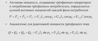
Using the power calculator , you can independently calculate power by current and voltage for single-phase (220 V) and three-phase networks (380 V). The program also calculates power through resistance and voltage, or through current and resistance according to Ohm's law. The cos φ value is taken according to the instructions in the technical data sheet of the device, the average values of the tables below, or calculated independently using formulas. We recommend not changing the coefficient unless necessary and leaving it at 0.95. To get the calculation result, click the “ Calculate ” button.
Related regulatory documents:
- SP 256.1325800.2016 “Electrical installations of residential and public buildings. Rules for design and installation"
- SP 31-110-2003 “Design and installation of electrical installations of residential and public buildings”
- SP 76.13330.2016 “Electrical devices”
- GOST 31565-2012 “Cable products. Fire safety requirements"
- GOST 10434-82 “Electrical contact connections. Classification"
- GOST R 50571.1-93 “Electrical installations of buildings”
Power calculation formulas
Power is a physical quantity equal to the ratio of the amount of work to the time of doing this work. Electric current power (P) is a quantity that characterizes the rate of conversion of electrical energy into other types of energy. The international unit of measurement is Watt (W/W).
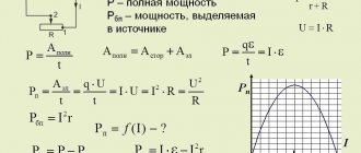
— Power by current and voltage (direct current): P = I × U — Power by current and voltage (single-phase alternating current): P = I × U × cos φ — Power by current and voltage (three-phase alternating current): P = I × U × cos φ × √3 - Power by current and resistance: P = I2 × R - Power by voltage and resistance: P = U2 / R
- I – current strength, A;
- U – voltage, V;
- R – resistance, Ohm;
- cos φ – power factor.
What does current power depend on?
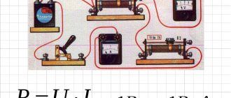
Electric current strength and voltage are the two main components that make up this indicator. In practice, this can easily be explained using the example of a small light bulb receiving a current of 1 A at a voltage of 1 V. Its power will be 1 W.
A more realistic example is accounting for consumed electricity using the formula W=IUt, where t is the operating time. The higher it is, the greater the volume of electricity and the higher the bill for its payment in the utility bill.
Calculation of cosine phi (cos φ)
φ is the shift angle between the phase of current and voltage, and if the latter leads the current, the shift is considered positive, if it lags, it is negative.
cos φ is a dimensionless quantity that is equal to the ratio of active power to total power and shows how efficiently energy is used.
Formula for calculating cosine phi: cos φ = S / P
- S – total power, VA (Volt-ampere);
- P – active power, W.
Active power (P) is the real, useful, real power, this load absorbs all the energy and turns it into useful work, such as light from a light bulb. There is no phase shift.
Formula for calculating active power: P (W) = I × U × cos φ
Reactive power (Q) is watt-free (useless) power, which is characterized by the fact that it does not participate in work, but is transmitted back to the source. The presence of a reactive component is considered a detrimental characteristic of a circuit, since the main purpose of the existing power supply is to reduce costs, and not to pump it back and forth. This effect is created by coils and capacitors.
Formula for calculating reactive power: P (VAR) = I × U × sin φ
The total power of an electrical appliance (S) is a total value that includes both active and reactive components of power.
Formula for calculating apparent power: S (VA) = I × U or S = √( P2 + Q2)
Once again about power: active, reactive, apparent (P, Q, S), as well as power factor (PF)
From a client’s letter: Tell me, for God’s sake, why the power of the UPS is indicated in Volt-Amps, and not in the usual kilowatts. It's very stressful. After all, everyone has long been accustomed to kilowatts. And the power of all devices is mainly indicated in kW. Alexei. June 21, 2007
The technical characteristics of any UPS indicate the apparent power [kVA] and active power [kW] - they characterize the load capacity of the UPS. Example, see photos below:
The power of not all devices is indicated in W, for example:
- The power of transformers is indicated in VA: https://www.mstator.ru/products/sonstige/powertransf (TP transformers: see appendix) https://metz.by/download_files/catalog/transform/tsgl__tszgl__tszglf.pdf (TSGL transformers: see application)
- The power of capacitors is indicated in Var: https://www.elcod.spb.ru/catalog/k78-39.pdf (capacitors K78-39: see appendix) https://www.kvar.su/produkciya/25-nizkogo- napraygeniya-vbi (UK capacitors: see appendix)
- For examples of other loads, see the appendices below.
The power characteristics of the load can be accurately specified by one single parameter (active power in W) only for the case of direct current, since in a direct current circuit there is only one type of resistance - active resistance.
The power characteristics of the load for the case of alternating current cannot be accurately specified by one single parameter, since in the alternating current circuit there are two different types of resistance - active and reactive. Therefore, only two parameters: active power and reactive power accurately characterize the load.
The operating principles of active and reactive resistance are completely different. Active resistance - irreversibly converts electrical energy into other types of energy (thermal, light, etc.) - examples: incandescent lamp, electric heater (paragraph 39, Physics 11th grade V.A. Kasyanov M.: Bustard, 2007).
Reactance - alternately accumulates energy and then releases it back into the network - examples: capacitor, inductor (paragraph 40,41, Physics 11th grade V.A. Kasyanov M.: Bustard, 2007).
Further in any textbook on electrical engineering you can read that active power (dissipated by active resistance) is measured in watts, and reactive power (circulating through reactance) is measured in vars; Also, to characterize the load power, two more parameters are used: apparent power and power factor. All these 4 parameters:
- Active power: designation P , unit: Watt
- Reactive power: designation Q , unit: VAR (Volt Ampere reactive)
- Apparent power: designation S , unit: VA (Volt Ampere)
- Power factor: designation k or cosФ , unit of measurement: dimensionless quantity
These parameters are related by the relations: S*S=P*P+Q*Q, cosФ=k=P/S
CosФ also called power factor ( Power Factor - PF )
Therefore, in electrical engineering, any two of these parameters are specified to characterize power, since the rest can be found from these two.
For example, electric motors, lamps (discharge) - in those. data indicated P[kW] and cosФ: https://www.mez.by/dvigatel/air_table2.shtml (AIR engines: see appendix) https://www.mscom.ru/katalog.php?num=38 ( DRL lamps: see appendix) (for examples of technical data of different loads, see appendix below)
It's the same with power supplies. Their power (load capacity) is characterized by one parameter for DC power supplies - active power (W), and two parameters for sources. AC power supply. Typically these two parameters are apparent power (VA) and active power (W). See, for example, the parameters of the diesel generator set and the UPS.
Most office and household appliances are active (no or little reactance), so their power is indicated in Watts. In this case, when calculating the load, the UPS power value in Watts is used. If the load is computers with power supplies (PSUs) without input power factor correction (APFC), a laser printer, a refrigerator, an air conditioner, an electric motor (for example, a submersible pump or a motor as part of a machine tool), fluorescent ballast lamps, etc., all outputs are used in the calculation. . UPS data: kVA, kW, overload characteristics, etc.
See electrical engineering textbooks, for example:
1. Evdokimov F. E. Theoretical foundations of electrical engineering. - M.: Publishing House, 2004.
2. Nemtsov M.V. Electrical engineering and electronics. - M.: Publishing House, 2007.
3. Chastoedov L. A. Electrical engineering. - M.: Higher School, 1989.
Also see AC power, Power factor, Electrical resistance, Reactance https://en.wikipedia.org (translation: https://electron287.narod.ru/pages/page1.html)
Application
Example 1: the power of transformers and autotransformers is indicated in VA (Volt Amperes)
Power transformers with a rated output power of 25-60 VA https://www.mstator.ru/products/sonstige/powertransf (TP transformers)
https://metz.by/download_files/catalog/transform/tsgl__tszgl__tszglf.pdf (TSGL transformers)
| Single-phase autotransformers | |||
| TDGC2-0.5 kVa, 2A | AOSN-2-220-82 | ||
| TDGC2-1.0 kVa, 4A | Latr 1.25 | AOSN-4-220-82 | |
| TDGC2-2.0 kVa, 8A | Latr 2.5 | AOSN-8-220-82 | |
| TDGC2-3.0 kVa, 12A | |||
| TDGC2-4.0 kVa, 16A | |||
| TDGC2-5.0 kVa, 20A | AOSN-20-220 | ||
| TDGC2-7.0 kVa, 28A | |||
| TDGC2-10 kVa, 40A | AOMN-40-220 | ||
| TDGC2-15 kVa, 60A | |||
| TDGC2-20 kVa, 80A | |||
https://www.gstransformers.com/products/voltage-regulators.html (LATR / laboratory autotransformers TDGC2)
Example 2: the power of capacitors is indicated in VAR (Volt Amperes reactive)
https://www.elcod.spb.ru/catalog/k78-39.pdf (capacitors K78-39)
https://www.kvar.su/produkciya/25-nizkogo-napraygeniya-vbi (UK capacitors)
Example 3: technical data for electric motors contains active power (kW) and cosF
For loads such as electric motors, lamps (discharge), computer power supplies, combined loads, etc., the technical data indicates P [kW] and cosФ (active power and power factor) or S [kVA] and cosФ (apparent power and power factor) power).
https://www.mez.by/dvigatel/air_table2.shtml (AIR engines)
https://www.weiku.com/products/10359463/Stainless_Steel_cutting_machine.html (combined load – steel plasma cutting machine / Inverter Plasma cutter LGK160 (IGBT)
Technical data of discharge lamps contain active power (kW) and cosФ https://www.mscom.ru/katalog.php?num=38 (DRL lamps)
https://www.silverstonetek.com.tw/product.php?pid=365&area=en (PC power supply)
Appendix 1
If the load has a high power factor (0.8 ... 1.0), then its properties approach those of a resistive load. Such a load is ideal both for the network line and for power sources, because does not generate reactive currents and powers in the system.
If the load has a low power factor (less than 0.8 ... 1.0), then large reactive currents (and powers) circulate in the power line. This parasitic phenomenon leads to increased losses in the line wires (heating, etc.), disruption of the operating mode of sources (generators) and network transformers, as well as other problems.
Therefore, many countries have adopted standards regulating the power factor of equipment.
Addendum 2
Single-load equipment (for example, a PC power supply unit) and multi-component combined equipment (for example, an industrial milling machine containing several motors, a PC, lighting, etc.) have low power factors (less than 0.8) of internal units (for example, a PC power supply rectifier or an electric motor have power factor 0.6 .. 0.8). Therefore, nowadays most equipment has a power factor correction input unit. In this case, the input power factor is 0.9 ... 1.0, which corresponds to regulatory standards.
Appendix 3: Important Note Regarding UPS Power Factor and Voltage Stabilizers
The load capacity of the UPS and diesel generator set is normalized to a standard industrial load (power factor 0.8 with an inductive nature). For example, UPS 100 kVA / 80 kW. This means that the device can supply a resistive load with a maximum power of 80 kW, or a mixed (reactive-reactive) load with a maximum power of 100 kVA with an inductive power factor of 0.8.
With voltage stabilizers the situation is different. For the stabilizer, the load power factor is indifferent. For example, a 100 kVA voltage stabilizer. This means that the device can supply an active load with a maximum power of 100 kW, or any other (purely active, purely reactive, mixed) power of 100 kVA or 100 kVAr with any power factor of a capacitive or inductive nature. Please note that this is valid for a linear load (without higher current harmonics). With large harmonic distortions of the load current (high SOI), the output power of the stabilizer is reduced.
Addendum 4
Illustrative examples of pure active and pure reactive loads:
- A 100 W incandescent lamp is connected to an alternating current network of 220 VAC - everywhere in the circuit there is conduction current (through the wire conductors and the tungsten filament of the lamp). Load (lamp) characteristics: power S=P~=100 VA=100 W, PF=1 => all electrical power is active, which means it is completely absorbed in the lamp and converted into heat and light power.
- A 7 µF non-polar capacitor is connected to an alternating current network of 220 VAC - there is a conduction current in the wire circuit, and a bias current flows inside the capacitor (through the dielectric). Characteristics of the load (capacitor): power S=Q~=100 VA=100 VAr, PF=0 => all electrical power is reactive, which means it constantly circulates from the source to the load and back, again to the load, etc.
Addendum 5
To indicate the predominant reactance (inductive or capacitive), the power factor is assigned the sign:
+ (plus) – if the total reactance is inductive (example: PF=+0.5). The current phase lags behind the voltage phase by an angle Ф.
— (minus) – if the total reactance is capacitive (example: PF=-0.5). The current phase advances the voltage phase by angle F.
Appendix 6
In various fields of technology, power can be either useful or parasitic, REGARDLESS of whether it is active or reactive. For example, it is necessary to distinguish between the active useful power dissipated in the workload and the active parasitic power dissipated in the power line. So, for example, in electrical engineering, when calculating active and reactive powers, most often active power is the useful power transmitted to the load and is a real (not imaginary) quantity. And in electronics, when calculating capacitors or calculating transmission lines themselves, active power is parasitic power lost to heat up the capacitor (or line) and is an imaginary quantity. Moreover, division into imaginary and non-imaginary quantities is carried out only for the convenience of calculations. In fact, all physical quantities are of course real.
Additional questions
Question 1: Why do all electrical engineering textbooks, when calculating AC circuits, use imaginary numbers/quantities (for example, reactive power, reactance, etc.) that do not exist in reality?
Answer: Yes, all individual quantities in the surrounding world are real. Including temperature, reactance, etc. The use of imaginary (complex) numbers is only a mathematical technique that facilitates calculations. The result of the calculation is a necessarily real number. Example: reactive power of a load (capacitor) of 20 kVAr is a real energy flow, that is, real Watts circulating in the source-load circuit. But in order to distinguish these Watts from the Watts irretrievably absorbed by the load, they decided to call these “circulating Watts” reactive Volt Amperes [6].
Note: Previously, only single quantities were used in physics, and when calculating, all mathematical quantities corresponded to the real quantities of the surrounding world. For example, distance equals speed times time (S=v*t). Then, with the development of physics, that is, as more complex objects were studied (light, waves, alternating electric current, atom, space, etc.), such a large number of physical quantities appeared that it became impossible to calculate each one separately. This is not only a problem of manual calculation, but also a problem of compiling computer programs. To solve this problem, close single quantities began to be combined into more complex ones (including 2 or more single quantities), subject to transformation laws known in mathematics. This is how scalar (single) quantities (temperature, etc.), vector and complex dual quantities (impedance, etc.), triple vector quantities (magnetic field vector, etc.), and more complex quantities appeared - matrices and tensors (dielectric constant tensor, tensor Ricci and others). To simplify calculations in electrical engineering, the following imaginary (complex) dual quantities are used:
- Total resistance (impedance) Z=R+iX
- Apparent power S=P+iQ
- Dielectric constant e=e'+ie"
- Magnetic permeability m=m'+im"
- and etc.
Question 2:
The page https://en.wikipedia.org/wiki/Ac_power shows SPQ Ф on a complex, that is, imaginary/non-existent plane. What does all this have to do with reality?
Answer: It is difficult to carry out calculations with real sinusoids, therefore, to simplify the calculations, use a vector (complex) representation as in Fig. higher. But this does not mean that the SPQs shown in the figure are not related to reality. Real SPQ values can be presented in the usual form, based on measurements of sinusoidal signals with an oscilloscope. The values of SPQ Ф IU in the alternating current circuit “source-load” depend on the load. Below is an example [5] of real sinusoidal signals SPQ and Ф for the case of a load consisting of active and reactive (inductive) resistances connected in series.
Question 3: Using a conventional current clamp and a multimeter, a load current of 10 A and a load voltage of 225 V were measured. We multiply and get the load power in W: 10 A · 225V = 2250 W.
Answer: You have obtained (calculated) the total load power of 2250 VA. Therefore, your answer will only be valid if your load is purely resistive, then indeed Volt Ampere is equal to Watt. For all other types of loads (for example, an electric motor) - no. To measure all the characteristics of any arbitrary load, you must use a network analyzer, for example APPA137:
See further reading, for example:
[1]. Evdokimov F. E. Theoretical foundations of electrical engineering. - M.: Publishing House, 2004.
[2]. Nemtsov M.V. Electrical engineering and electronics. - M.: Publishing House, 2007.
[3]. Chastoedov L. A. Electrical engineering. - M.: Higher School, 1989.
[4]. AC power, Power factor, Electrical resistance, Reactance https://en.wikipedia.org (translation: https://electron287.narod.ru/pages/page1.html)
[5]. Theory and calculation of low power transformers Yu.N. Starodubtsev / RadioSoft Moscow 2005 / rev d25d5r4feb2013
[6]. International System of Units, SI, see e.g. GOST 8.417-2002. UNITS OF QUANTITIES
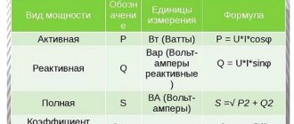
Cosine phi for various consumers - table
| Name of electrical appliance | cos φ |
| Boiler | 1 |
| Bulgarian | 0.8 |
| Vacuum pump | 0.85 |
| Induction furnaces | 0.85 |
| Compressor | 0.7 |
| Computer | 0.95 |
| Coffee maker | 1 |
| Gas discharge lamps | 0.4-0.6 |
| Fluorescent lamps | 0.95 |
| Incandescent lamps | 1 |
| Heater | 1 |
| Hammer | 0.85 |
| Vacuum cleaner | 0.9 |
| Microwave | 1 |
| Washing machine | 0.9 |
| TV | 1 |
| Iron | 1 |
| Hairdryer | 1 |
| Fridge | 0.95 |
| Electric drill | 0.85 |
| Electric motors | 0.7-0.8 |
| Electric stove | 1 |
| Electric arc welding | 0.3-0.6 |
| Electric kettle | 1 |
Definition
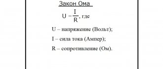
The load on an electrical circuit determines how much current flows through it. If the current is constant, then in most cases a resistor of a certain resistance can be defined as the load equivalent. Then the power is calculated using one of the formulas:
P=U*I
P=I2*R
P=U2/R
The same formula is used to determine the total power in an alternating current circuit.
The load is divided into two main types:
- Active is a resistive load, such as heating elements, incandescent lamps and the like.
- Reactive - it can be inductive (motors, starter coils, solenoids) and capacitive (capacitor units, etc.).
The latter only happens with alternating current, for example, in a sinusoidal current circuit, which is exactly what you have in your sockets. We will explain below what the difference between active and reactive energy is in simple language, so that the information becomes clear to novice electricians.
Instruments for measuring quantities
Measurements of electrical quantities are made with special devices. Current is measured with an ammeter, voltage with a voltmeter, and power can be measured with a wattmeter, or calculated using a formula from the values of the first two values.
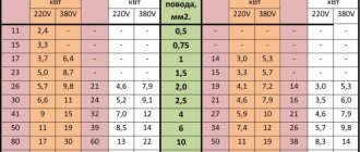
Using an online calculator, you can calculate not only the current at a known consumer power, but also the cross-section of the wires needed for electrical wiring.
Calculating the current strength and wiring parameters according to the power of electricity consumers is a very important part of the design of a building or apartment, so you need to approach this carefully and responsibly.
How to find out the current strength, knowing the power and voltage.
To answer the question of how to determine current, you need to divide the electrical voltage by the total number of watts. In this case, you can do all the necessary calculations yourself, or you can resort to a special online calculator.
Calculation of power indicator by amperes and watts.
You can find out the electricity consumption by the current strength of the resistor by multiplying the former by the resistance, expressed in Ohms. The result is a value expressed in volts multiplied by ohms. It turns out ampere.
Note! If there is no resistance, you need to divide the watt indicator by the current energy, that is, you should divide the watts by amperes and you will get the value of electricity in volts. You can understand the power reading through the amount of electricity with electrical voltage by multiplying the corresponding readings from the device.
Calculation of electricity through electrical power and voltage
Principles of current calculation
Knowing the strength of the current flowing in the circuit in amperes is important for calculating the cross-section of the wire used to lay the wiring and choosing a circuit breaker that protects the network from overloads. A cross-sectional value that is larger than necessary causes additional costs, while a smaller one will cause overheating of the electrical wiring, which can lead to melting of the cable insulation and a fire.
The correct choice of the machine is also important, since a large current reserve will be useless if the switch trips late and the equipment has time to fail, and too small a reserve will cause a very frequent emergency shutdown when the power consumption increases within acceptable limits.
According to Ohm's law, current can be calculated as the ratio of the voltage between two points to the resistance of this section of the circuit (the resistance of the wire itself). This parameter of the wire depends on its material, length and cross-section. When using standard materials (aluminum or copper), the only parameter that can be influenced is the cross-section of the conductor. And it depends on the expected current flow.
The current in a 220 V outlet usually does not exceed 6 amperes. This means that the total power of electrical appliances connected to the outlet should not exceed 1300 W. Otherwise, special wires with a larger cross-section must be laid.
Compensation methods
We have already found out how reactive currents affect the operation of devices and equipment with inductive or capacitive loads. To reduce losses in electrical networks with sinusoidal current, they are equipped with additional compensation devices.
The principle of operation of compensation settings is based on the properties of inductances and capacitances for phase shifts in opposite directions. For example, if the winding of an electric motor shifts the phase by an angle φ, then this shift can be compensated by a capacitor of appropriate capacity, which shifts the phase by an amount - φ. Then the resulting shift will be zero.
In practice, compensating devices are connected in parallel to the loads. Most often they consist of blocks of high-capacity capacitors located in separate cabinets. One such capacitor installation is shown in Figure 3. The picture shows groups of capacitors used to compensate for voltage shifts in various devices with inductive windings.
Rice. 3. Compensation device
Compensation of reactive power with capacitive loads is well illustrated by the graphs in Figure 4. Note how the effectiveness of compensation depends on the network voltage. The higher the mains voltage, the more difficult it is to compensate for parasitic currents (graph 3).
Rice. 4. Reactive power compensation using capacitors
Compensation devices are often installed in manufacturing workshops where many electrically driven devices operate. In this case, the loss of electricity is quite noticeable, and the quality of the current is greatly deteriorated. Capacitor units successfully solve such problems.
Why are there different powers?
The difference arises because electricity consumers may differ in type of load. Active species, receiving energy from a source, completely transform it into work. They have no phase shift, and the current sinusoid follows the voltage sinusoid.
Learn to easily calculate the power consumption of an electrical appliance
For reactive types of loads, when receiving energy from a source, they first accumulate it for some time. After which they give it back to the source, also for some time. A phase shift occurs between the current and voltage sinusoids of 900.
For your information. The transmission of electricity over a distance to the consumer is directional in nature. Such a return is harmful to the process. Therefore, the reactive part S is one of the negative characteristics of electrical circuits.
Difference between kVA and kW
As you know, kVA is kilovolt-ampere, kW is kilowatt, this is a significant difference.
How to convert kVA to kW
To do this, you can choose several options:
- approximate translation;
- using an online calculator;
- application of a mathematical formula.
Any of the methods will help convert one value to another.
When converting kva values to kW, it is necessary to work with the same digit of numbers. For example, when trying to determine 10 kva - how many kW, you need to pay attention to the prefix “kilo”. It is equal to 1*103, for example: 1 kV = 1*103V. This means that 10 kVA is 1*104 VA.
It all depends on the accuracy to what decimal place you need to get the result of converting one value to another. To obtain information and use it in everyday situations, an approximate translation is sufficient. For preliminary calculations, you can use an online calculator. To calculate exact values when designing and calculating networks, mathematical calculations are needed.
Examples of calculations
Below are practical applications of the calculations. Several options are being considered.
Approximate conversion of kVA to kW
How to convert watts to amperes
In this case, the result is obtained with a small error that can be neglected.
20% is subtracted from the useful power S, and active P is obtained. If we take 1 kVA, then 20% of it will be 0.2 kVA. Therefore, 1– 0.2 = 0.8. This means that for a quick approximate translation it is enough to multiply this value by 0.8. For example, S = 300 kVA, which means P = 300 * 0.8 = 240 kW.
Approximate conversion of kW to KVA
In this case, you need to do the opposite - add 20%, which means dividing by 0.8. Let P = 200 kW, which means S = 200/0.8 = 250 kVA.
Exact translation formula for converting kVA to kW
To convert kVA to kW, you can use a formula that looks like this:
P = S*cosϕ,
Where:
- P – active power, kW;
- S – total, kVA (kva);
- cosϕ – coefficient.
This way you can convert any apparent power values into an active value.
Formula for converting kW to kVA
You need to translate in reverse order by changing the formula:
S=P/ cosϕ.
All parameters included in it are already known.
Attention! An electricity meter, installed to measure the amount of energy consumed, calculates how many kilowatts per hour are supplied to the electricity subscriber. If the subscriber uses reactive type consumers for his needs, he will pay for full power. It will be greater than its practically spent active value.
Passport data displayed on devices
Of practical importance for ordinary citizens, the difference between these two values is significant only when purchasing instruments and devices. Not all manufacturer-designated data indicate both values at once. To understand exactly what power a particular device will produce, you need to be able to convert one value into another.