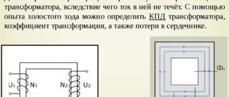
Good day to all! In the last article I talked about the equivalent circuit of a transformer. In this article I will tell you how to calculate power losses in a transformer. The temperature of its heating depends on the power losses in the transformer, so they significantly affect the design parameters. When calculating a transformer, power losses should be limited by correctly selecting parameters and quantities that affect losses.
To assemble a radio-electronic device, you can pre-make a DIY KIT kit using the link.
Components of power losses in a transformer
The total or total power losses in a transformer ∆р consist mainly of two parts: losses in the core ∆рс and losses in the coils ∆рк. The power losses present in the transformer structural elements are quite small and are usually not taken into account.
When calculating a transformer, in addition to the above values, the ratio of power losses ν and the ratio of total power losses ∆р to output power P2, called the loss coefficient kpot, are important
Quite often, power losses ∆рс and ∆рк are called losses “in steel” and losses “in copper”, but this is not entirely correct, since not only steel, but also various alloys are used as the core material, and winding wires are used as the material - not only copper, but also aluminum.
Power losses in coils ∆рд, in addition to the main part - losses in windings - include losses in the dielectric: conductor insulation, interlayer and inter-winding ∆рд. However, this component of power losses begins to influence the overall losses only for high-voltage, high-frequency transformers. Let's consider the components of transformer power losses.
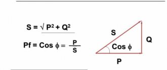
Calculation of reactive power loss in a transformer.
The total reactive power losses of a power transformer form:
- reactive power of the magnetization of the idle magnetic circuit Q0 = Qхх = Sn*Iхх/100, where Sn is the rated power of the transformer (see calculation of transformer power in this material), Iхх is the no-load current in% according to the passport data or reference book;
- reactive power of stray fields Qр = Sn*Кз²*Uкз/100, where Uкз is the short-circuit voltage in %, Кз is the load factor, which is determined by the ratio of the total load power of the transformer to its rated power Sp/St.
Total reactive power losses of the transformer Qpt = Sn*Iхх/100 + Sn*Кз²*Uкз/100 = Sn*Iхх/100 + Кз²*Uкз/100).
Power losses in the transformer core
In the ∆рс transformer core, power losses are caused by the expenditure of magnetic field energy to remagnetize the material from which the core is made.
The magnetic field energy in the general case is determined by the following expression
where EC(t) is the change in voltage over one period,
i(t) – change in current over one period.
In accordance with the law of electromagnetic induction and the theorem on the circulation of the magnetic field strength vector, we obtain
where S is the cross-sectional area of the magnetic circuit,
lcp is the average length of the magnetic field line.
Since ferromagnetic cores have hysteresis, there is no unambiguous functional relationship between the intensity H and the magnetic field induction B in it. However, when the core is remagnetized from –Hmax to Hmax, we can assume that any value of magnetic field strength H corresponds to only two values of magnetic induction B: on the ascending and descending branches. That is, after a full magnetization reversal cycle, the ferromagnet will return to the same state from which the process began. Then the integrand has the physical meaning of the heat given off by the core during one cycle of alternation.
Physical meaning of magnetic losses in the core.
Since the power loss in the core ∆рс is defined as work per unit of time, then by transforming the previous formula, we obtain an expression for calculating the power loss in the core
where f is the magnetization reversal frequency of the magnetic circuit.
The integrand is numerically equal to the area of the shaded section of the hysteresis loop. Thus, the calculation of this integral is the calculation of specific losses.
In practice, there is no need to calculate specific losses, since reference data exist for the developed ferromagnetic materials. Therefore, different formulas are used depending on the known reference data.
The following expression is quite widespread for high-frequency materials, where specific losses have the dimension W/(cm3Hz)
PSV – specific volumetric losses in the magnetic circuit,
Ve is the equivalent volume of the magnetic core,
f – magnetization reversal frequency.
So for domestic ferrites the value of specific volumetric losses is
| Ferrite grade | PSV, μW/(cm3*Hz), at a frequency of 10-20 kHz | At induction V, T | ||
| T, °C | ||||
| +25 | +100 | +120 | ||
| 2500NMS1 | 10,5 | 8,7 | — | 0,2 |
| 2500NMS2 | 8,5 | 6 | — | 0,2 |
| 2500NMS5 | 9,0 | 7,6 | — | 0.2 (at 100 kHz) |
| 3000NMS | 2,5 | — | 2,5 | 0,1 |
In addition to this expression, there are more complex ways to calculate power losses in the transformer core. Often, reference books provide specific volumetric losses PSV in W/cm3 or specific mass losses PSM in W/kg. In this case, power losses are calculated using the following expressions
where ρ is the density of the material,
f1, B1 – basic design parameters at which power losses in the core were measured,
α and β are power parameters that depend on the specific material; their values can be found in reference books.
| Material | PSV W/cm3 | α | β |
| 2000NM-A | 0,142 | 1,2 | 2,4 |
| 2000NM-17 | 0,272 | 1,2 | 2,8 |
| 3000NM-A | 0,208 | 1,2 | 2,8 |
| 1500NM3 | 0,093 | 1,2 | 2,2 |
| 2000NM3 | 0,178 | 1,3 | 2,7 |
For these materials, B1 = 1 T, f1 = 1 kHz.
| Material | Thickness, mm | PSM, W/kg | α | β |
| 34NKMP | 0,1 | 2,2 | 1,65 | 1,7 |
| 40NKMP | 0,05 | 2,8 | 1,5 | 1,3 |
| 50NP | 0,1 | 5 | 1,4 | 1,5 |
| 79NM | 0,1 | 1,4 | 1,65 | 2,0 |
| 68NMP | 0,05 | 2,2 | 1,55 | 1,7 |
| 80НХС | 0,05 | 1,2 | 1,5 | 2,0 |
For these materials, B1 = 0.5 T, f1 = 1 kHz.
Quite detailed reference materials are produced for foreign-made ferrites. To calculate losses in cores made of these ferrites, the coefficient of specific volumetric losses PV ( Relative core losses ) measured in kW/m3 is used. For this parameter, detailed graphical dependences on frequency f, magnetic induction B and temperature T are provided.
Dependence of specific PV losses for N72 ferrite on various parameters.
Therefore, to find power losses for cores made of such materials, it is enough to use the following expression
where PV – specific volumetric losses under specific conditions,
Ve is the effective volume of the core.
Example 1 – Determination of voltage loss when the load is connected at the end of the line
Determine the voltage loss in a three-phase overhead line with a rated voltage Unom. = 10 kV with a length of l = 2 km, supplying electrical equipment of a utility company with a power of P = 100 kW. Load power factor cosϕ = 0.8. The line is made of aluminum wires of grade A-25 with a cross-section of 25 mm2, the distance between phases is 600 mm.
Solution.
1. Determine the active resistance of wire grade A-25:
Where:
- γ – the value of specific conductivity for copper and aluminum wires at a temperature of 20 °C is accepted: for copper wires – 53 m/Ohm*mm2; for aluminum wires – 31.7 m/Ohm*mm2;
- s – nominal wire (cable) cross-section, mm2;
You can also find in those. literature another formula for determining the active resistance of a wire (cable):
Where:
- ρ – the resistivity value is accepted: for copper wires - 0.017-0.018 Ohm*mm2/m; for aluminum wires – 0.026 - 0.028 Ohm*mm2/m, see table 1.14 [L2. p.30].
2. Determine the inductive reactance for wire grade A-25 [L1.s.420]:
Where:
- Dsr. – average geometric distance between the axes of the wires, mm;
- d = 6.40 mm – wire diameter, for wire grade A-25. The value of the wire diameter can be determined according to GOST 839-80 - “Bare wires for overhead power lines” in tables 1 – 4. In this calculation, I give the value of the wire diameter, only for wire grade A; for other brands of wires, you can find the wire diameter values directly in GOST itself;
- µ - relative magnetic permeability for non-ferrous metals (non-magnetic) is equal to 1, for steel wires µ can reach values of 103 and even more.
2.1 Determine the average geometric distance between the axes of three wires laid in the same plane [L1.p.419]:
where: the distance between the wires of the first and second phase D1-2 = 600 mm, between the second and third D2-3 = 600 mm, between the first and third D1-3 = 600 + 25 + 600 = 1225 mm.
3. Determine the power factor tgϕ, knowing cosϕ:
4. Determine the voltage loss in the line [L1.s.422]:
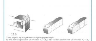
How to calculate power losses in stacked cores?
The specific losses of magnetic material in stacked cores exceed those of pressed cores. The reason for the increase in losses is the negative impact of technological operations during the manufacture of cores. To take into account this influence, a loss increase factor kp is introduced:
where Рсн – specific power losses in a stacked (tape or laminated) core,
РV/ – specific losses of the material from which the core plates or strips are made,
kp – loss increase factor.
The values of this coefficient depend on the manufacturing technology, type of material, operating frequency and type of core. So for stacked cores (LS and ShS) made of electrical steel, it is determined by the following expression
And for split strip cores made of iron-nickel alloys
where ψа is a parameter taking into account the type of core. For detachable cores (ST, BT) ψа = 3, and for closed ones (TT) it is ψа = 1.
The table below shows typical values of the loss magnification factor
| Core type | Material | kp values at frequency in Hz | ||||
| View | Thickness | 50 | 400 | 2000 | 10000 | |
| AL and closed LS | Steels and alloys | 0,15-0,35 | 1,15 | 1,2 | 1,25 | 1,3 |
| 0,05 | — | 1,25 | 1,35 | 1,4 | ||
| Split drugs | Email those. become | 0,15-0,35 | 1,3 | 1,4 | 1,5 | 1,6 |
| 0,05 | — | 1,5 | 1,6 | 1,7 | ||
| 50N, 33NKMS | 0,05-0,1 | — | 1,7 | 1,8 | 1,9 | |
| 80НХС, 79НМ | 0,05-0,1 | — | 2,5 | 2,8 | 3 | |
The values of the additional loss coefficient kp are given for medium-sized cores (several tens of W). For smaller cores, the value of this coefficient must be increased by 1.2 - 1.3 times, and for large cores reduced by 1.2 - 1.3 times.
How to calculate power losses in transformer windings?
Power losses in the transformer windings ∆рк directly depend on their active resistance Ri. In addition, it is necessary to take into account the increase in resistance due to additional factors (increase in temperature and skin effect). In general, power losses in the windings are determined by the following expression
where N is the number of secondary windings,
рki – losses in the i-th winding,
Ii – current strength in the i-th winding,
Ri is the resistance of the i-th winding.
The winding resistance is calculated using a well-known formula, through resistivity
where lw is the average length of the winding turn, cm,
w – number of winding turns,
q – conductor cross-section, mm2,
ρ – resistivity of the conductor material, Ohm*mm2/m.
This expression is quite inconvenient to use in practice. Most often, the dimensions of the core are known, as well as its main parameters (areas and volumes). Therefore, you can use the following expression for power losses in the transformer windings
where koki is the window fill factor for the i-th winding,
Vki – geometric volume occupied by the i-th winding, cm3,
ji – current density for the i-th winding, a/mm2,
Soki – cross-sectional area of the i-th winding, mm2,
If the parameters ρ, j, kok are the same for all windings or their average values are taken, then we obtain the following expression
where Vk is the geometric volume occupied by the entire coil, cm3.
As already mentioned, the transformer heats up during operation. At the same time, the active resistance of the windings changes. The resistivity of a conductor with increasing temperature can be calculated using the following expressions
where kτ is a coefficient taking into account the increase in resistance due to rising temperature,
ρ20 – conductor resistivity at a temperature of 20°C,
αρ – temperature coefficient of resistance, for copper and aluminum αρ = 0.004 1/°С,
tp – operating temperature of the transformer, °C.
Since in most cases reference books indicate the resistivity of materials at a temperature of 20°C, the expression can be simplified
where τ is the transformer overheating.
The effect of temperature on the resistance of a transformer winding must always be taken into account when calculating the voltage drop across them.
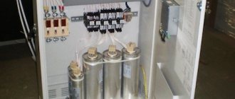
Electricity losses in a capacitor installation
Reactive power sources can be of two types: static CG, which include BSK and STC, and rotating CG - synchronous machines, which include SC and synchronous motors (SM).
Specific power losses in the BC do not exceed 3 kW/Mvar. Losses in STC depend on their design (ratio of capacitor and reactor power) and average 6 kW/Mvar. Power losses in synchronous machines also depend on the machine design, voltage and rotation speed. They are determined by the formula
Synchronous motors are installed based on the requirements of technological processes, so it is not the feasibility of their installation that is considered, but the feasibility of their additional use as a HRSG. By generating reactive power, they consume additional active power, so when assessing the total reduction in losses in the network and SD, this must be taken into account. No-load losses in the SD, unlike in the SC, are not taken into account, since they also occur when the reactive power of the SD is not used.
The values of D1 and D2 for most SDs operated in networks of electricity consumers are given in [23]. Losses in the LED depend not only on D1 and D2, but also on the voltage at the LED input and other mode parameters that do not remain constant during operation. In estimated calculations, losses in the SD when it is fully loaded in terms of reactive power (βQ = 1) can be determined using the formula
Almost all SDs are manufactured with a nominal cos ϕ = 0.9 (tg ϕ = 0.5), so their maximum available reactive power is half the rated power of the SD. Specific losses in SD ∆psd, kW/Mvar, at maximum reactive power are determined by the formula
With a decrease in the SD load in terms of reactive power (βQ < 1), the specific losses decrease and amount to (1 + βQ) / 2 of the nominal losses.
The coefficients асд and bсд are given in table. 7.1. There, for comparison, the specific losses calculated using formula (7.39) in LEDs with a power of 1 and 5 MW are given.
Table 7.1
Power loss coefficients in LEDs
From the data in table. 7.1 it follows that specific losses are lower in SDs with a high number of revolutions and high power. For the best SDs in terms of using their reactive power, the specific losses are 8 kW/Mvar, and for the worst ones – 35 kW/Mvar, which is 3–12 times more than the losses in the BSK.
Synchronous compensators are used specifically to compensate for reactive power, so the specific losses in them are determined taking into account no-load losses. Their values range from 30 kW/Mvar for a 5 Mvar SC to 12 kW/Mvar for a 320 Mvar SC. Even greater losses occur when generators of existing stations that are not used for a certain period for their main purpose or generators of uneconomical stations taken out of normal operation are used as SCs. Losses in the SC are discussed in paragraph 2.2.2.
In terms of specific losses, SCs are significantly inferior to capacitor units. However, it should be remembered that the installation of a power supply system is carried out not only with the aim of reducing losses, but also (primarily) with the aim of increasing the stability of the operating modes of power systems. The properties of electrical machines are such that with a sharp decrease in voltage, they sharply increase the output reactive power, maintaining the mode. Capacitors behave in exactly the opposite way: as the voltage drops, their power decreases in proportion to the square of the voltage at the point of their connection, exacerbating the shortage of reactive power.