Active and reactive power are consumers of electrical energy for the purpose of consuming this energy. The consumer is interested in that energy, the consumption of which benefits him; this energy can be called useful, but in electrical engineering it is usually called active. This is the energy that is used to heat rooms, cook food, produce cold, and is converted into mechanical energy (the operation of electric drills, hammer drills, electric pumps, etc.).
In addition to active electricity, there is also reactive electricity. This is that part of the total energy that is not spent on useful work. As is clear from the above, total power is active and reactive power as a whole.
In the concepts of active and reactive power, conflicting interests of consumers of electrical energy and its suppliers collide. It is beneficial for the consumer to pay only for the useful electricity he has consumed, while it is beneficial for the supplier to receive payment for the amount of active and reactive electricity. Is it possible to reconcile these seemingly contradictory requirements? Yes, if you reduce the amount of reactive electricity to zero. Let's consider whether this is possible and how close one can get to the ideal.
Active and reactive power
Active power
There are electricity consumers whose total and active power are the same. These are consumers whose load is represented by active resistances (resistors). Among household electrical appliances, examples of such a load are incandescent lamps, electric stoves, frying cabinets and ovens, heaters, irons, soldering irons, etc.
Indicated in the passport of these devices, it is both active and reactive power. This is the case when the load power can be determined using the formula known from the school physics course by multiplying the load current by the voltage in the network. Current is measured in amperes (A), voltage in volts (V), power in watts (W). An electric stove burner in a network with a voltage of 220 V at a current of 4.5 A consumes power 4.5 x 220 = 990 (W).
Reactive power
Sometimes, walking down the street, you can see that the glass of the balconies is covered from the inside with a shiny thin film. This film was removed from defective electrical capacitors installed for certain purposes at distribution substations supplying powerful consumers of electrical energy. A capacitor is a typical consumer of reactive power. In contrast to active power consumers, where the main design element is a certain electrically conductive material (tungsten conductor in incandescent lamps, nichrome spiral in an electric stove, etc.). In a capacitor, the main element is a non-conducting dielectric (thin polymer film or oil-soaked paper).
Reactive capacitive power
The beautiful shiny films that you saw on the balcony are capacitor linings made of conductive thin material. The capacitor is remarkable in that it can accumulate electrical energy and then release it - a kind of battery. If you connect a capacitor to a DC network, it will be charged with a short-term current pulse, and then no current will flow through it. You can return the capacitor to its original state by disconnecting it from the voltage source and connecting a load to its plates. Electric current will flow through the load for some time, and an ideal capacitor will supply exactly as much electrical energy to the load as it received when charging. A light bulb connected to the terminals of the capacitor may flash for a short time, the electrical resistor will heat up, and a careless person may be “shocked” or even killed if there is sufficient voltage at the terminals and the amount of electricity stored.
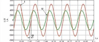
An interesting picture is obtained when connecting a capacitor to a source of alternating electrical voltage. Since the polarity and instantaneous voltage value of an alternating voltage source constantly changes (in a home electrical network according to a law close to sinusoidal). The capacitor will continuously charge and discharge, and alternating current will continuously flow through it. But this current will not be in phase with the voltage of the alternating voltage source, but will advance it by 90°, i.e. for a quarter period.
This will lead to the fact that the capacitor consumes energy from the network for half the period of alternating voltage, and releases half of the period, while the total active electrical power consumed is zero. But, since a significant current flows through the capacitor, which can be measured with an ammeter, it is customary to say that the capacitor is a consumer of reactive electrical power.
Reactive power is calculated as the product of current and voltage, but the unit of measurement is no longer watt, but volt-ampere reactive (VAr). Thus, a current of about 0.3 A flows through an electrical capacitor with a capacity of 4 μF connected to a 220 V network with a frequency of 50 Hz. This means that the capacitor consumes 0.3 x 220 = 66 (VAr) reactive power - comparable to the power of an average incandescent lamp, but the capacitor, unlike a lamp, does not glow or heat up.
Reactive inductive power
If the current in a capacitor leads the voltage, are there consumers where the current lags the voltage? Yes, and such consumers, unlike capacitive consumers, are called inductive, while remaining consumers of reactive energy. A typical inductive electrical load is a coil with a certain number of turns of highly conductive wire wound around a closed core of special magnetic material.
Active load
Devices with active loads include heating devices (irons, electric stoves, incandescent lamps, electric kettles). Such devices produce heat and light. They do not contain inductance or capacitance. A resistive load converts electrical energy into light and heat.
A reactive load contains capacitance and inductance. These parameters have the quality of collecting energy and then sending it to the network. An example would be an electric motor, an electric meat grinder, a household tool (vacuum cleaner, food processor). That is, all devices that contain electric motors.
Compensation according to theory
From the above graph it is quite clear how to achieve a reduction in parasitic currents up to their complete elimination, at least theoretically. To do this, you should connect a capacitor of the appropriate capacitance in parallel with the inductive load. Vectors when added will give zero, and only the useful active component will remain.
The calculation is made using the formula:
- C = 1 / (2πFX), where X is the total reactance of all devices connected to the network; F – supply voltage frequency (we have 50 Hz);
It seems like - what could be simpler? Multiply “X” and “pi” by 50 and divide. However, everything is somewhat more complicated.
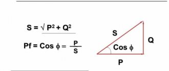
Capacity Triangle
To understand the reactive load, consider the power triangle.
where P is active power, which is measured in Watts and is used to perform useful work;
Q – reactive, which is measured in Vars and is used to create an electromagnetic field;
S – total power is used to calculate electrical circuits.
To calculate the total power, we use the Pythagorean theorem: S 2 =P 2 +Q 2. Or using the formula: S=U*I, where U is the voltage reading across the load, I is the reading of the ammeter, which is connected in series with the load. The calculations also use the power factor - cosφ. On devices that relate to reactive loads, active power and cosφ are usually indicated. Using these parameters you can also get full power.
Sometimes devices indicate total power, but cosφ is not indicated. In this case, a coefficient of 0.7 is applied.
What about in practice?
The formula is not complicated, but defining and calculating X is not so easy. To do this, you need to take all the data about the devices, find out their reactance, and in vector form, and then... In fact, no one does this, except for students in laboratory work.
Reactive power can be determined in another way, using a special device - a phase meter, indicating the cosine phi, or by comparing the readings of a wattmeter, ammeter and voltmeter.
The matter is complicated by the fact that in the conditions of a real production process the load value is constantly changing, since some machines are turned on during operation, while others, on the contrary, are disconnected from the network, as required by technological regulations. Accordingly, ongoing measures to monitor the situation are necessary. During night shifts, lighting is on; in winter, the air in the workshops can be heated, and in summer, it can be cooled. One way or another, reactive power compensation is carried out on the basis of theoretical calculations with a large share of practical measurements of cos φ.
Nonlinear load
It has the peculiarity that voltage and current are not proportional. Nonlinear loads include televisions, stereos, electronic desktop clocks, computers and its components. The nonlinearity itself is due to the fact that this electronic device uses switching power supplies. To recharge the capacitors in the switching power supply, the top of a sine wave is sufficient.
The rest of the time, the capacitor does not consume energy from the network. In this case, the current has a pulse quality. What does this all lead to? This causes the sine wave to become distorted. But not all electronic devices work with a distorted sine wave. This problem is solved through the use of double conversion stabilizers, where mains power is converted to constant power. Then it is converted from a constant into a variable of the desired shape and amplitude.
Compensator device
A conventional power factor compensator is a standard sized metal cabinet with a monitoring and control panel on the front panel, which is usually openable. At the bottom of it there are sets of capacitors (batteries). This arrangement is due to a simple consideration: the electrical containers are quite heavy, and it is quite logical to strive to make the structure more stable. In the upper part, at the operator’s eye level, there are the necessary control devices, including a phase indicator, with which you can judge the value of the power factor. There are also various indications, including emergency ones, controls (on and off, switching to manual mode, etc.). The comparison of readings from measuring sensors and the development of control actions (connecting capacitors of the required value) are assessed by a circuit based on a microprocessor. Actuators operate quickly and silently; they are usually built on powerful thyristors.
Starting current
When calculating, it is necessary to take into account the starting currents of the device. For example, the resistance of the filament in a light bulb at the moment of switching on is 10 times less than in operating mode. Therefore, the starting current of this light bulb is 10 times greater. After some time, it will begin to consume the power that is recorded in the data of this light bulb. Therefore, when turned on, it burns out due to high inrush currents.
In electronic equipment, until the capacitor in the power supply is charged, an inrush current is also generated.
In electric motors, a starting current is also generated until the engine reaches rated speed.
In heating devices, a starting current is generated until the coil heats up to the standby temperature.
Automation and intelligent algorithms
Currently, there are systems that allow you to reliably keep cos φ in the range from 0.9 to 1. Since the capacitors are connected discretely, it is impossible to achieve an ideal result, but the economic effect of the automatic reactive power compensator still provides a very good one. The operation of this device is based on intelligent algorithms that ensure operation immediately after switching on, most often even without additional settings. Technological advances in computer technology make it possible to achieve uniform connection of all stages of capacitor banks in order to avoid premature failure of one or two of them. Response times are also minimized, and additional chokes reduce the magnitude of voltage drop during transients. A modern enterprise power control panel has an appropriate ergonomic layout, which creates conditions for the operator to quickly assess the situation, and in the event of an accident or failure, he will receive an immediate alarm signal. The price of such a cabinet is considerable, but it is worth paying for it, it brings benefits.
The meaning of reactive load
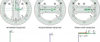
In an electrical circuit with a reactive load, the current phase and the voltage phase do not coincide in time. Depending on the nature of the connected equipment, the voltage either leads the current (in inductance) or lags behind it (in capacitance). Vector diagrams are used to describe issues. Here, the same direction of the voltage and current vector indicates the coincidence of phases. And if the vectors are depicted at a certain angle, then this is the advance or lag of the phase of the corresponding vector (voltage or current). Let's look at each of them.
In inductance, voltage always leads current. The “distance” between phases is measured in degrees, which is clearly illustrated in vector diagrams. The angle between the vectors is denoted by the Greek letter "Phi".
In an idealized inductance, the phase angle is 90 degrees. But in reality this is determined by the full load in the circuit, and in reality it cannot do without a resistive (active) component and a parasitic (in this case) capacitive component.
In a capacitor, the situation is the opposite - the current leads the voltage, because the inductance, when charging, consumes a large current, which decreases as it charges. Although it is more often said that voltage lags behind current.
To put it briefly and clearly, these shifts can be explained by the laws of commutation, according to which the voltage in a capacitor cannot change instantly, and the current in inductance cannot change.
What it is
The first thing you need to know is what active energy is. This is the amount consumed by the load in normal resistance. This applies to heating devices (kettles, electric fireplaces, microwave ovens, etc.). The power consumption of these devices is completely active. In such devices, the energy used is permanently and completely transformed into another energy group.
Power is indicated by the symbol P and is expressed in Watts (W).
To find this value, you must use the formula:
P = U * I;
In this case, the work will be carried out without changes.
Inductive power graph
In circuits with alternating voltage there is only active energy, because the indicators of instantaneous and average power converge there.
Inductive work - current passes through it and lags behind voltage. As a result, reactive energy will be consumed.
For example, such a load is used in asynchronous motors, no-load sensors, reactors, current transformers, rectifiers and other converters.
Inductive asynchronous motor
Power triangle and cosine Phi
If you take the entire circuit, analyze its composition, phases of currents and voltages, then construct a vector diagram. After this, draw the active one along the horizontal axis, and the reactive one along the vertical axis and connect the ends of these vectors with the resulting vector - you get a triangle of powers.
It expresses the ratio of active and reactive power, and the vector connecting the ends of the two previous vectors will express the total power. This all sounds too dry and confusing, so look at the picture below:
The letter P denotes active power, Q – reactive power, S – apparent power.
The total power formula is:
The most attentive readers probably noticed the similarity of the formula to the Pythagorean theorem.
- P – W, kW (Watts);
- Q – VAR, kVAr (reactive volt-amperes);
- S – VA (Volt-Amps);
Connecting and disconnecting capacitors
The simplest and most obvious way to solve the problem is to place a special worker near the phase meter who would turn on or off the required number of capacitors, achieving the minimum deviation of the needle from unity. This is what they did at first, but practice has shown that the notorious human factor does not always allow one to achieve the desired effect. In any case, compensation for reactive power, which is most often inductive in nature, is carried out by connecting an electrical capacitance of the appropriate size, but it is better to do this in automatic mode, otherwise a careless employee may subject his or her enterprise to a large fine. Again, this work cannot be called skilled; it is quite amenable to automation. The simplest circuit includes an optical electron pair of a light emitter and a light receiver. The arrow has crossed the minimum value, which means you need to add capacity.
Calculations
To calculate the total power, use the formula in complex form. For example, for a generator the calculation looks like:
And for the consumer:
But let’s put this knowledge into practice and figure out how to calculate power consumption. As you know, we, ordinary consumers, pay only for the consumption of the active component of electricity:
P=S*cosФ
Here we see a new value of cosФ. This is the power factor, where Ф is the angle between the active and full components of the triangle. Then:
cosФ=P/S
In turn, reactive power is calculated using the formula:
Q = U*I*sinФ
To reinforce the information, watch the video lecture:
All of the above is also true for a three-phase circuit; only the formulas will differ.
Theory and practice
All theoretical calculations have greater value the more applicable they are in practice. The picture at any developed industrial enterprise is as follows: most of the electricity is consumed by motors (synchronous, asynchronous, single-phase, three-phase) and other machines. But there are also transformers. The conclusion is simple: in real production conditions, inductive reactive power predominates. It should be noted that enterprises install not one electricity meter, as in houses and apartments, but two, one of which is active, and the other - it’s easy to guess which one. And the relevant authorities mercilessly fine for excessive consumption of energy “driven” through power lines in vain, so the administration is vitally interested in calculating reactive power and taking measures to reduce it. It is clear that it is impossible to solve this problem without electrical capacitance.
Inductor in a DC circuit.
So, first of all, let's figure out what happens in the coil itself when current flows. If the current does not change its value, then the coil has no effect on it. Does this mean that in the case of direct current the use of inductors should not be considered? But no