A magnetic starter is a device designed for switching power electrical circuits. The first thing you need to do before servicing or repairing a magnetic starter is to study the documentation for this starter, or, as they do in the 21st century, look it up on the Internet. It is also worth knowing the weak points of magnetic starters - contact groups. It is the contact groups that need careful examination. It is worth paying attention to the fastening elements and the body, which will be discussed in the article.
Visual inspection
Repair of a magnetic starter begins with an external inspection. An external inspection involves inspecting the body and fastening elements for cracks and chips. If there are cracks on the fastening elements, this affects the volume of operation, and also, if the starter falls off and its “toad” design, then there is a danger that it will turn on the power circuit. In addition, it is worth paying attention to protective covers.
It is also worth inspecting the starter for contamination. If there is a large amount of dust, oil, traces of liquid (crystalline growths) and other aggressive elements on the housing, then it is worth reconsidering the method of protecting the starter from aggressive environmental influences. Increase the degree of dust and moisture protection. If this is not done, the coil in the starter, which will be described below, will quickly become damp and fail, and the metal parts will become corroded.
Magnetic starters, as the name suggests, were conceived as a switching device for starting electric motors. Therefore, the number of power poles in these devices is almost always equal to three - according to the number of phases of the network. Starters are often equipped with thermal overload relays and a housing with start and stop buttons.
But the starter turned out to be a very convenient and functional thing. A wide range of rated currents, small dimensions and the possibility of autonomous installation outside any switchgear or panel have led to the fact that magnetic starters have become widely used in everyday life for connecting various powerful electrical receivers, for example, heating boilers, to the network.
Like any other electrical device, a magnetic starter also periodically needs repair and maintenance.
How does a magnetic starter work?
In general, this is at least a coil of thin wire in varnish insulation, housed in the same plastic housing with contacts. Contacts, as usual, are divided into movable, mechanically connected to the spring-loaded core of the coil, and fixed, permanently located in the upper part of the housing.
At the same time, for starters designed for a current of 20 amperes or more, one can clearly distinguish between three pairs of power pairs of contacts, and pairs of contacts of auxiliary control circuits, designed for low currents. The number of low-current contacts is practically unlimited, especially since for many starters it is possible to purchase additional contact attachments that allow you to assemble very complex circuits on starters.
This design provides the starter with a not particularly high degree of protection from external influences - at the IP00-IP30 level. If it is necessary to achieve a greater degree of protection, you will have to use starters in an additional protective casing, often equipped with their own buttons for starting, stopping and returning the thermal relay, if any.
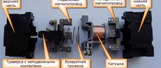
Rice. 1. PML magnetic starter device:
1 - base made of heat-resistant plastic, 2 - fixed part of the magnetic circuit, 3 - moving part of the magnetic circuit, 4 - electromagnetic control coil, 5 - contact clamps, 6 - metal platform (for starters rated over 25 A) 7 - traverse with moving contacts, 8 - mounting screw, 9 - return spring, 10 - aluminum rings, 11 - fixed contact, 12 - clip with a notch for fixing the conductors.
The maintenance program for magnetic starters is simple and includes the following points:
1. External inspection for damage and chips of the housing, as well as removal of contamination (not only from the surface of the housing, but also from the surface of the electromagnet core). Chips and damage to the housing occur not only due to shocks and falls, but also due to prolonged exposure to vibrations caused by the operation of a worn-out AC network and faulty installation of the starter, as well as its own defects.
If damage to the housing has led to the fact that the starter cannot be securely fastened, or its contacts cannot open/close freely, then there is simply no other option than replacing the housing or starter.
Special attention should be paid to checking the presence of all parts and components of the starter. For example, a movable contact plate along with its preload spring can easily be “lost” - a new one will be required.
2. Revision of the mechanical part. The operating spring, which ensures the contacts are broken, is tested. It should be quite rigid, the turns should not get too close. The movement of the starter armature relative to the housing is checked: it is necessary that there are no jams or difficulties during movement.
Checking the progress is carried out by closing the contacts “by hand”. If there are mechanical jams, you can resort to lubrication or grinding of the rubbing parts.
3. Cleaning contacts is a measure that is best avoided when carrying out maintenance of serviceable magnetic starters.
The highly conductive layer of movable and stationary contacts is relatively thin, therefore, if you rub a file on it during each maintenance, the starter will very soon fail. A file will only be needed if there are obvious traces of carbon deposits or melting on the contacts. Sandpaper for cleaning contacts is strictly excluded.
When closing, all contacts of the starter must fit tightly against each other over the entire surface, without displacements or tilts, the presence of which indicates the need to adjust the mechanical part.
4. If the starter contains metal parts within the housing, or is located in a metal casing, then you must make sure that there is no circuit between these parts to be grounded and the power contacts . For all starters in general, it is necessary to check the absence of short circuits between the individual power poles. At the household level, for these purposes it is enough to use a conventional multimeter. A megohmmeter is used in production, and the insulation resistance is standardized - at least 0.5 Mohm.
5. The starter coil is thoroughly inspected. Cracks in the frame, damage, carbon deposits and melting of insulation are all sure signs of significant problems. It is better to replace a coil with such symptoms.
Of course, usually it is possible to determine an interturn short circuit in a coil only during operation by indirect signs, such as an increased hum when the starter is operating. However, if you systematically check the active resistance of the coil wire, you can notice a significant and sharp decrease. This sign speaks quite eloquently about the malfunction of the coil, which theoretically can be rewound, but in practice is easier to replace.
6. However, an increased hum during starter operation can be caused by some other reasons besides defects in the coil itself. For example, a misalignment may occur during its installation, the voltage level in the network may be insufficient, or the return spring may be selected too strong.
All these factors lead to the fact that the armature does not fit tightly enough to the core when closing. The consequence will be a higher coil current due to its lower inductive reactance (hence the hum), as well as burning of the power contacts.
You can check the tightness of the surfaces of the magnetic circuits of the core and armature using an ordinary thin blank piece of paper placed between these parts. At least 70 percent of the surface must be in contact - then the contact will be reliable.
7. If there is a thermal overload relay, its setting should be checked . At industrial enterprises this is done using special test benches. Unfortunately, at the household level it is almost impossible to load and test the relay. To do this, you can take the relay to a special laboratory, or, as a last resort, test it using a known load of a higher rating.
Repair of a magnetic starter is carried out based on the results of maintenance and usually comes down to replacing parts and assemblies that cannot be restored or adjusted. Such spare parts can be: a coil, individual contacts and even the contact group as a whole, housing parts, springs, screws and clamping plates.
Contact groups
Basically, maintenance and repair of magnetic starters comes down to contact groups. To inspect them, you need to open the protective cover; the first thing we pay attention to is the contact groups. If there is slight carbon deposits, you need to clean it off with fine-grain sandpaper. As you can see in the photo, there is no oxidation. This means that the chosen method of protecting the starter from aggressive environmental factors is chosen correctly.
If traces of oxide, darkening, or rust are visible on the metal parts, then in this case it is necessary to definitely reconsider the method of installing the starter. Or rather, install it in a more dust- and moisture-proof shell. Then we inspect the contact groups for the presence of carbon deposits, deposits, and cavities. Depending on the degree of damage to the contact groups, a decision is made on repair or replacement.
Example of faulty moving contacts that must be replaced
The photo above shows a contact that “survived” after a short circuit. The remaining two have failed and need to be replaced.
Repair of contactors and magnetic starters often comes down to repair of contact groups. This is done by cleaning carbon deposits from the contact pad. If shells and build-ups are found during inspection, then these places need to be leveled with a flat, small file or needle file. This is done in the same plane as the contact pad of the fixed contact. To ensure a better effect, you can grind both contact pads on the moving and fixed elements.
It is highly not recommended to do all these operations with sandpaper or sandpaper, since in this case it is very difficult to maintain a flat surface. An unmaintained plane means a decrease in the contact area, and this in turn causes excessive heating and premature failure of the magnetic starter. It is worth inspecting both the main and auxiliary contact groups.
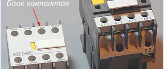
Contact block or contact attachment.
A movable contact system is built inside the contact block (contact attachment), which is rigidly connected to the contact system of the magnetic starter and becomes one with it. The attachment is attached to the top of the starter, where special skids with hooks
.
The contact system of the set-top box consists of two pairs of normally closed
and two pairs
of normally open
contacts.
To go further, let's immediately understand: what are normally closed and normally open contacts. The figure below schematically shows the button
with a pair of contacts numbered
1-2
and
3-4
, which are fixed on a vertical axis.
The right side of the figure shows a graphical
representation of these contacts used on electrical circuit diagrams.
Normally open (NO)
The contact in the non-working state is always
open
, that is, not closed.
In the figure it is indicated by a pair 1–2
, and in order for current to pass through it, the contact must
be closed
.
Normally closed (NC)
When not in use, the contact is always
closed
and current can flow through it.
In the figure, such a contact is indicated by a pair 3–4
, and in order to stop the flow of current through it, the contact must
be opened
.
Now, if you press the button, the normally open contact 1-2 will close
, and the normally closed 3-4
will open
. This is what the picture below shows.
Let's return to the contact block. In the initial state, when the magnetic starter is de-energized
, normally open contacts
53NO–54NO
and
83NO–84NO
are open, and normally closed contacts
61NC–62NC
and
71NC–72NC
are closed. This is indicated by a nameplate with the numbers of the contact terminals located on the side wall of the contact block, and the arrow shows the direction of movement of the contact group.
Armature and electromagnet
The armature and magnetic circuit of a magnetic starter rarely suffer, but sometimes it happens that the package in which the sheets of cold-rolled anisotropic electrical steel are collected crumbles. This is usually caused by a manufacturing defect. But this happens extremely rarely.
The most common damage that occurs when repairing a magnetic starter on the armature and magnetic circuit is corrosion. Switching is carried out by moving the armature downwards under the action of an electromagnet and upwards under the action of springs. As a result of the vibration created, rust flakes off and can accumulate in moving parts, which can jam over time.
Springs, mounting bolts and screws
Springs and bolts should be inspected for corrosion. Springs lose their properties over time, which means they must be replaced. A bad spring causes the load to be released slowly, which means that the arc created during the release process will act on the contact groups longer, which will accelerate their wear. You should also not install an overly strong spring.
This will lead to incomplete closure of the magnetic flux, which will cause additional heating of the coil, and this in turn will damage it. Bolts and screws with signs of severe corrosion must be replaced. It is also worth inspecting the threaded connections. Threads on bolts that have been lapped, damaged by corrosion or mechanically damaged must not be used; such bolts must also be replaced.
Magnetic starter coil
When the magnetic starter coil is pulled out from its place, the first step is to inspect its section (the frame on which the copper wire is wound) for cracks and chips. In our case, the copper wire is filled with plastic. If there is damage, the starter will make a lot of noise during operation. Then you need to pay attention to the coil itself. There should be no traces of heating (blackening) on the paper/plastic, and there should also be no burning smell. Typically, the main data is indicated on the side of the reels.
This is the number of turns, operating voltage, type of current (if alternating, then frequency). The brand and thickness of the wire and the brand of the starter for which it is intended are also indicated. Determining the presence of an interturn short circuit is quite difficult. For example, by abnormally low or high resistance. If the reel looks the same as in the photo above, then it can be rewound. If it is filled with plastic, it must be replaced.
Varieties
Magnetic starters are designed mainly to control the operation of 3-phase electric motors at a remote level. The main operations carried out using magnetic starters are starting, shutting down or reversing.
An auxiliary function of the starter, together with a thermal relay, is to protect the electric motor from excessive loads. There are starter circuits with voltage limiters based on semiconductor elements. According to the connection diagrams, loads can be reversible or non-reversible.
According to the type of location, magnetic starters are classified:
- Open type . Placed in protected cabinets, panels, and other places inaccessible to moisture, dust and other harmful factors.
- Secure execution . Installed in rooms with a low dust content in the air, preventing access of water to the device.
- Waterproof design . They are mounted inside buildings, outside under equipped canopies from water and sun.
Auxiliary classification:
- Block with buttons on the starter body. Starters without reverse have two buttons: Start and Stop, devices with reverse are equipped with three buttons, two of them are the same as in the previous version, a Start back button has been added. Some versions of the devices include a lamp indicating switching on.
- Devices with auxiliary contacts for signals and interlocks. They are used in various combinations, as closing or disconnecting. Contacts can be built-in or placed on a separate stand. Sometimes auxiliary contacts are used as part of the overall starter circuit. In devices with reverse, electrical interlocking is performed using additional contacts.
- The value of voltage and current of the power winding.
- Thermal relay. Its property is the nominal current at which the relay does not operate at medium settings. This current value can be adjusted within certain limits from the rated current value.