LED lamps perform their functions fully with high-quality power supply. Even slight fluctuations in current in the circuit provoke visible ripples and impair durability. Similar problems are solved in the process of charging batteries. To correctly solve the above and other problems, a current stabilizer on a transistor is suitable. Self-assembly will help ensure the operating parameters of the device are in strict accordance with the technical specifications. The information presented below will be useful for choosing the optimal electrical circuit.
Connecting a powerful LED to the power supply through a specialized integrated stabilizer
Types of stabilizers
In the simplest version, a current limiter is used from a resistor installed in series with the LED. Standard devices are connected to 5V (12V) sources. By increasing the voltage, accuracy can be improved, but efficiency will decrease.
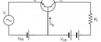
Transistor voltage stabilizer
The maximum values of the electrical parameters of the source should be 10% greater than the operating values of the LED. The voltage drop is indicated in the accompanying documentation. To calculate the resistor ( R ), use the following formula:
(Up — Uc)/ Ipot,
Where:
- Up – power source voltage;
- Uc – drop on the LED;
- Ipot – current consumption.
Example:
- Up = 5 V;
- Uc = 2.5 V;
- Ipot = 0.25 A;
- R = (5-2.5)/0.3 ≈ 8.33 Ohm;
- the closest value is 8.45 Ohm;
- resistor power = 0.3*0.3*8.45 ≈ 0.75 W.
For your information. The last line of the calculation clearly demonstrates energy losses. A heating resistor will increase the ambient temperature.
Improved circuits are assembled from the following components:
- the transformer changes the amplitude of the signal as needed;
- For rectification, a conventional bridge of diodes is used;
- capacitors smooth out ripples;
- Resistors limit the output currents.
The transistor voltage and current stabilizer is economical. Electrical resistance in the input circuit is installed as a sensor. This component complements the zener diode. Changing the voltage at the emitter allows you to adjust the output parameters automatically without control or intervention from the user.
Instead of a zener diode, the emitter junction of a bipolar transistor can perform similar functions when properly connected to an electrical circuit.
A field-effect transistor is used to connect chains of several LEDs and other powerful loads
Instead of a set of several radio components, it is more convenient to use specialized microcircuits. Such products provide high accuracy in maintaining the operating parameters of the output signal. As in the example with a zener diode, a resistor is installed in a certain circuit to quickly detect changes in current strength.
Separately, it should be noted the pulse circuits of stabilizers. Such products are created on the basis of high-speed electronic keys. The main feature is the ability to operate with relatively high output voltages.
Multifunctional device
Drivers for 220 V LEDs are of average complexity. Setting them up can take a lot of time, requiring setup experience. Such a driver can be extracted from LED lamps, spotlights and lamps with a faulty LED circuit. Most of them can also be modified by recognizing the converter controller model. The parameters are usually set by one or more resistors.
Until recently, the universal module XL4015 was very popular. According to its characteristics, it is suitable for connecting high power LEDs (up to 100 Watt). The standard version of its case is soldered to a board that acts as a radiator. To improve the cooling of the XL4015, the circuit must be modified to install a heatsink on the device box.
Many users simply place it on top, however, the efficiency of such an installation is quite low. It is advisable to place the cooling system at the bottom of the board, opposite the soldering joint of the microcircuit. For optimal quality, it can be unsoldered and installed on a full-fledged radiator using thermal paste. The wires will need to be extended. Additional cooling can also be installed for diodes, which will significantly increase the efficiency of the entire circuit.
Among the drivers, adjustable is considered the most universal. A variable resistor must be installed, which sets the number of amperes. These characteristics are usually specified in the following documents:
- In the accompanying documentation for the microcircuit.
- In datasheet.
- In the standard connection diagram.
Without additional cooling of the microcircuit, such devices can withstand 1-3 A (in accordance with the model of the pulse-width modulation controller). The main disadvantage of these drivers is excessive heating of the diode and inductor. Above 3 A, cooling of the powerful diode and controller will be required. The choke is replaced with a more suitable one or rewound with a thick wire.
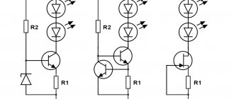
A simple current stabilizer on a transistor
Field-effect transistor current stabilizer circuit
Component parameters and circuit performance characteristics:
- R1 select 1-15 Ohm;
- R2 – from 150 to 250 Ohm;
- D1 – zener diode or resistor of a suitable value;
- Q1 – KT 818 or equivalent;
- power supply voltage – from 8 to 40 V;
- output current – 0.5-4.5A.
Current stabilizer on one transistor
Explanations:
- R2 and D2 form a standard voltage divider;
- by changing the potential on the base, the current in the collector circuit is adjusted;
- when connecting a powerful load, R1 gets very hot;
- to accurately adjust the output parameters, set the variable resistance R2 (change the saturation threshold at the corresponding semiconductor junction);
- if necessary, increase the output current using a composite transistor.
If the calculation is made accurately, in the operating range the current is stabilized with minimal losses. A simple circuit is easy to make with your own hands, even without previous assembly experience.
Where can I order parts?
To search for high-quality and at the same time affordable modules, you can use the Aliexpress website. The cost will be 2-3 times cheaper compared to other stores. Therefore, for testing, it is better to order 2-3 pieces at once (for example, 12 volts) at the lowest price. On the site you can find any current stabilizer for free sale, including highly specialized ones. If you have the appropriate experience, you can make a spectrometer worth 100,000 rubles for just 10,000 rubles. The difference of 90% is, as a rule, a markup for the brand (plus slightly redesigned Chinese software).
Chinese online stores took the leading positions in the range of current converters, power supplies and drivers. Orders arrive in 98% of cases. Prices for a DC-DC converter start at 35 rubles. More expensive versions may differ in the presence of two or three trimming resistors, instead of one. It is better to place an order in advance.
Assembling a current stabilizer from two transistors
Current stabilizer on LM317 for LEDs
In this circuit, the sensor functions are performed by resistor R2. Its value when connecting LEDs is selected using the formula:
0.6/In (load current).
An increase in In opens VT2, which, in turn, locks the transition of transistor VT1.
Stabilizer with two transistors
Experts consider a significant voltage drop across the main transistor to be a disadvantage of the circuit. There are no problems when connecting several LEDs. However, as the load increases, it is necessary to place VT1 on a large radiator to ensure effective ventilation of the working volume. Such solutions are used to create powerful chargers.
Design and operating principle
The stabilizer ensures constant current when it deviates.
The stabilizer ensures constant operating current of LED diodes when it deviates from the norm. It prevents overheating and burnout of LEDs, maintains constant flow during voltage surges or battery discharge.
The simplest device consists of a transformer, a rectifier bridge connected to resistors and capacitors. The action of the stabilizer is based on the following principles:
- supplying current to the transformer and changing its limiting frequency to the mains frequency - 50 Hz;
- voltage adjustment to increase and decrease with subsequent frequency equalization to 30 Hz.
The conversion process also uses high-voltage rectifiers. They determine the polarity. Stabilization of the electric current is carried out using capacitors. Resistors are used to reduce interference.
Current relays on pulse stabilizer chips
To reduce losses and maintain a wide operating range, ready-made solutions are used. This section presents a switching current stabilizer on the MAX771 chip.
Switching stabilizer
The control voltage is supplied from the divider (R1, R2). If the level set by the manufacturer is exceeded, the output parameters are automatically adjusted.
Selecting a connection scheme
In practice, different engineering solutions are used. In particular, manufacturers offer switching power supplies to connect LED lamps. These devices perform their functions using frequency conversion and signal modulation. Microchips are installed to control the key. A throttle is used for measured energy storage.
Pulse current stabilizer
For simplicity, this article considers linear stabilization. Devices created according to this scheme do not create strong electromagnetic interference. This is the main difference from pulse analogues.
How to make an LED stabilizer
A simple design of a resistor, capacitor and zener diode can be assembled in just a few minutes. Use a universal mounting plate or a hinged assembly method. The electrical resistance rating is selected taking into account the load parameters. If necessary, install a homemade radiator from a suitable aluminum plate.
Zener diode power supply circuit
LM317
The use of LM317 (roll) does not even require any skills or knowledge of electronics. The number of external elements in the circuits is minimal, so this is an affordable option for anyone. Its price is very low, its capabilities and applications have been tested and verified many times. Only it requires good cooling, this is its main drawback. The only thing you should be wary of is low-quality Chinese LM317 microcircuits, which have worse parameters.
Due to the absence of excess noise at the output, linear stabilization microcircuits were used to power high-quality Hi-Fi and Hi-End DACs. For DACs, cleanliness of power plays a huge role, so some use batteries for this.
Stabilization circuit up to 10 amperes
The maximum power for the LM317 is 1.5 Amps. To increase the number of amperes, you can add a field-effect transistor or a regular one to the circuit. At the output it will be possible to get up to 10A, set by low-resistance resistance. In this diagram, the main load is taken by the KT825 transistor.
Another way is to install an analogue with higher technical characteristics on a larger cooling system.
Current stabilizers on microcircuits
The use of such an element base slightly increases the cost of the project. However, the use of high-quality microcircuits provides good stabilization characteristics over a wide range of input parameters. Given the good efficiency indicators, you can count on low energy consumption.
TL431
The left side of the figure shows a typical connection diagram for the TL 431 (DA1) microcircuit. The main function is noted - maintaining a voltage of 2.5 V across the control resistor.
Application of the TL 4310 chip
This design is suitable for connecting several dozen LEDs in series with a total power of 12-14 W. Power components are selected taking into account real needs. In the presented example, the voltage drop across the transistor will be 25-35V. Dissipates no more than 1.75 W. In this version, a radiator is not required.
The input resistor (R3) prevents damage to the capacitor when the unit is connected to the network. The load current is limited to a safe level by resistance R3. When choosing LEDs, experts recommend making a power reserve in order to extend their service life while reducing heat generation.
LM7805, LM7812
In the circuit design presented below, the input voltage should be increased. Its level should be 2.5-3V higher than the stabilization rating of this microcircuit.
Connection LM78**
The example shows a DC voltage stabilizer, which is designed for 9-11 W of connected load.
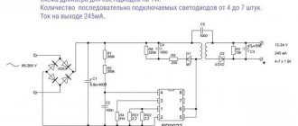
LM317
When connecting a 28-30 W load, this microcircuit provides current stabilization of 100 mA. Input voltage range – from 207 to 240 V.
Stabilizer and lamp connection diagram
The table in the figure shows the values of the adjustment resistor corresponding to certain output parameters.
When choosing a suitable scheme, you should take into account the following:
- minimum and maximum voltages in the power circuit;
- stabilization accuracy;
- device efficiency;
- the difficulty of making a certain design with your own hands;
- cost of components, consumables.
It is recommended to prepare a list of tools, devices, and measuring instruments in advance. Carefully following the instructions discussed above will help you create a functional stabilizer without errors and extra costs.
Regulator characteristics
Depending on their type, devices can be manufactured in portable or stationary versions. They can be installed in any position: vertical, ceiling, horizontal.
The main characteristics of the devices include the following parameters:
- Smooth adjustment. Indicates the minimum step with which the potential difference at the output changes. The smoother it is, the more accurately you can set the output voltage value.
- Operating power. It is characterized by the value of current that can pass through the device for a long time without damaging its electronic connections.
- Maximum power. The peak value that a device can withstand for a short time while maintaining its functionality.
- Input voltage range. These are the input signal values with which the device can operate.
- The range of the variable signal at the device output. Indicates the potential difference that the device can provide at the output.
- Type of adjustable signal. Both alternating and direct voltage can be supplied to the input of the device.
- Terms of Use. Indicates conditions under which the controller characteristics do not change.
- Control method. The output signal level can be set by the user manually or without his intervention.
Basic configuration
The main task of the stabilizer is to ensure constant output voltage and suppress ripple. The design of the stabilizer is based on the simplest circuit, but I chose each of its elements so that it ideally fulfills its function: To maximize input noise suppression, the resistance of the resistor R should be maximum, and the internal resistance of the reference voltage source Vref should be as low as possible. And the reference voltage driver will work better if it is powered from a high-resistance source. A stable current source (GST) meets these requirements.
For the high-voltage stabilizer, I used a GST with two transistors, which provides greater current stability when the supply voltage fluctuates.
For low-voltage stabilizers, you can use a similar circuit or just a single diode.
For high-voltage stabilizers, I chose a GST current value of about 5mA. For low-voltage stabilizers, you can choose a lower value.
The TL431 chip requires a minimum of 2 mA for normal operation.
Important note: The two-transistor GST can sometimes be excited if high-frequency transistors are used. Therefore, I chose MJ340/350 transistors which, as my experience shows, work stably
Zener diodes are quite noisy and also have a poor temperature coefficient. The output voltage when using them will vary depending on the ambient temperature, and even more so if your amplifier has active ventilation. In addition, the stability of their internal resistance also leaves much to be desired.
I used a TL431 as a voltage reference instead, as their noise performance is quite decent, they have low output impedance and a fairly wide output voltage range that can be set using a simple divider.
Are you here
Home › Design engineer › 3. Electrical equipment, electrical installations › 3. Section 3.
To obtain a more constant voltage across the load when the current consumed changes, a stabilizer is connected to the output of the rectifier, which can be made according to the circuit shown in Fig. 1. This device uses zener diode V5
and control transistor
V6
.
The calculation will allow you to select all elements of the stabilizer based on the specified output voltage Un
and maximum load current
In
.
However, both of these parameters should not exceed the parameters of the already calculated rectifier. And if this condition is violated, then the stabilizer is first calculated, and then the rectifier and power transformer. The stabilizer is calculated in the following order.
1. Determine the input voltage required for the stabilizer to operate (Uvyp)
at a given output
(Un)
:
Uvyp = Un + 3
,
Here, number 3, which characterizes the minimum voltage between the collector and emitter of the transistor, is taken based on the use of both silicon and germanium transistors. If the stabilizer is connected to a ready-made or already calculated rectifier, in further calculations it is necessary to use the real value of the rectified voltage Uvyp
.
2. Calculate the maximum power dissipated by the transistor:
Pmax = 1.3 (Uvyp - Un) In
,
3. Select a control transistor. Its maximum permissible power dissipation must be greater than the Pmax
, the maximum permissible voltage between the emitter and the collector is greater than
Uvyp
, and the maximum permissible collector current is greater than
In
.
4. Determine the maximum base current of the regulating transistor:
Ib.max = In / h21E min
,
where: h21Emin is the minimum current transfer coefficient of the selected (according to the reference book) transistor.
.
5. Select a suitable zener diode. Its stabilization voltage must be equal to the output voltage of the stabilizer, and the value of the maximum stabilization current must exceed the maximum base current Ib max
.
6. Calculate the resistance of resistor R1
:
R1 = (Uvyp - Ust) / (Ib max + Ist min)
,
Here R1 is the resistance of resistor R1, Ohm; Ust — zener diode stabilization voltage, V; Ib.max - calculated value of the maximum base current of the transistor, mA; Ist.min is the minimum stabilization current for a given zener diode, indicated in the reference book (usually 3...5 mA).
.
7. Determine the power dissipation of resistor R1
:
PR1 = (Uvyp - Ust)2 / R1
,
It may happen that a low-power zener diode is not suitable for the maximum stabilization current and you will have to choose a zener diode of significantly higher power - this happens with high consumption currents and using a transistor with a low h21E
.
In this case, it is advisable to introduce an additional low-power transistor V7
(Fig. 2), which will reduce the maximum load current for the zener diode (and therefore the stabilization current) by approximately
h21E
times and, accordingly, use a low-power zener diode.
The calculations presented here do not correct for changes in mains voltage, and also omit some other clarifications that complicate the calculations. It is easier to test the assembled stabilizer in action by changing its input voltage (or mains voltage) by ± 10% and more accurately select resistor R1 based on the greatest stability of the output voltage at maximum load current.
Stabilized regulated power supply with overload protection
Many amateur radio power supplies (PS) are made on KR142EN12, KR142EN22A, KR142EN24, etc. microcircuits. The lower limit of adjustment of these microcircuits is 1.2...1.3 V, but sometimes a voltage of 0.5...1 V is necessary. The author offers several technical power supply solutions based on these microcircuits.
The integrated circuit (IC) KR142EN12A (Fig. 1) is an adjustable voltage stabilizer of the compensation type in the KT-28-2 package, which allows you to power devices with a current of up to 1.5 A in the voltage range 1.2...37 V. This integrated stabilizer has thermally stable current protection and output short circuit protection.
Fig.1. IC KR142EN12A
Based on the KR142EN12A IC, you can build an adjustable power supply, the circuit of which (without a transformer and diode bridge) is shown in Fig. 2. The rectified input voltage is supplied from the diode bridge to capacitor C1. Transistor VT2 and chip DA1 should be located on the radiator. Heat sink flange DA1 is electrically connected to pin 2, so if DA1 and transistor VD2 are located on the same radiator, then they need to be isolated from each other. In the author's version, DA1 is installed on a separate small radiator, which is not galvanically connected to the radiator and transistor VT2.
Fig.2. Adjustable power supply on IC KR142EN12A
ADJUSTABLE POWER SUPPLY WITH OVERLOAD ALARM
An audible alarm allows the user to quickly respond to an emergency if an overload of the power source occurs during experiments with various electronic equipment. The diagram of a power supply with an audible alarm for excess current consumption is shown in the figure.
The diode rectifier VD1-VD4 is powered by a transformer, the secondary casing of which is designed for a voltage of 18 V with a load current of at least 1 A. The adjustable voltage stabilizer is made using transistors VT2 - VT5 according to a well-known circuit. The variable resistor R3 at the output of the stabilizer can set the voltage from 0 to +15 V.