Short abbreviations
When presenting information, it is customary to use abbreviations and acronyms on the forum, for example:
| Reduction | Short description |
| LED | Light Emitting Diode - LED (Light Emitting Diode) |
| MOSFET | Metal Oxide Semiconductor Field Effect Transistor - Field effect transistor with MOS gate structure |
| EEPROM | Electrically Erasable Programmable Read-Only Memory |
| eMMC | embedded Multimedia Memory Card - Built-in multimedia memory card |
| LCD | Liquid Crystal Display - Liquid crystal display (screen) |
| SCL | Serial Clock - I2C interface bus for transmitting a clock signal |
| S.D.A. | Serial Data - I2C interface bus for data exchange |
| ICSP | In-Circuit Serial Programming – Protocol for in-circuit serial programming |
| IIC, I2C | Inter-Integrated Circuit - Two-wire data exchange interface between chips |
| PCB | Printed Circuit Board |
| PWM | Pulse Width Modulation - Pulse Width Modulation |
| SPI | Serial Peripheral Interface Protocol - Serial peripheral interface protocol |
| USB | Universal Serial Bus - Universal serial bus |
| DMA | Direct Memory Access - Module for reading and writing RAM without using the processor |
| A.C. | Alternating Current |
| DC | Direct Current - Direct current |
| FM | Frequency Modulation - Frequency modulation (FM) |
| A.F.C. | Automatic Frequency Control - Automatic frequency control |
FAQ
After registering an account on the site, you can publish your question or answer in existing topics. Participation is absolutely free.
Who answers questions on the forum?
Reply to the topic : How to eliminate the buzzing of contactors?
Like all other tips, they are published by the entire community. Most of the participants are professional repairmen and electronics specialists.
How to find the necessary information on the forum?
The ability to search the entire site and file archive will appear after registration. A site search form will be displayed in the upper right corner.
What other brands can I ask?
For any reason. The most frequent answers for popular brands are LG, Samsung, Philips, Toshiba, Sony, Panasonic, Xiaomi, Sharp, JVC, DEXP, TCL, Hisense, and many others, including Chinese models.
What other files can I download here?
If you actively participate in the forum, you will have access to additional files and sections that are not displayed to guests - diagrams, firmware, reference books, repair methods and secrets, typical faults, service information.
useful links
Here are just useful links for craftsmen. Links are periodically updated, depending on the demand for topics.
Why is the magnetic starter humming?
Basic malfunctions of magnetic starters 1. Symptom of malfunction: “Stubborn goat” The starter does not turn on Cause. a) There is no power at the terminals of the upper contacts, there is no “zero” on the body. Remedy. Check the power supply at the contact terminals. If there is no voltage, apply power to the contacts. The voltage should be both between the contacts and relative to the housing. If there is no voltage between the housing, but there is voltage between the phases, then there is no “zero”. Check the neutral wire on the housing. b) The thermal relay has tripped or its contacts are faulty. Determine the reason for the operation of the thermal relay, eliminate it, cock the contacts of the thermal relay to the operating position (after the thermal elements have cooled). If the starter does not turn on, check the condition of the contacts. If the latter burn, clean or replace.
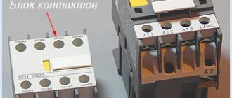
c) Break in the coil control circuit Ring the buttons, coil, thermal relay contacts and wires suitable for them (the stop button must ring, the start button must ring when you press it, the thermal relay contacts must ring in the operating position, the coil terminals must ring)), and also check the correct connection of the circuit: all elements of the circuit except the block contacts must be connected in series, the block contacts parallel to the start button. If necessary, replace faulty buttons, coils, thermal relay contacts or the relay itself, and wires.
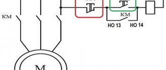
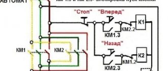
d) The wires of the stop button are connected to normally open contacts (Fig. 2): when you press the start and stop buttons simultaneously, the starter turns on, when you release the start button, the starter works, when you release the stop button, the starter turns off. Check which group of contacts the wires on the stop button are connected to (see Fig. 1). The contacts must be normally closed. Otherwise, reconnect the wires to normally closed ones; in the absence of the latter, replace the button.
e) The wires of the buttons are mixed up (Fig. 3). Ring the block contacts and between the stop and middle wires of the buttons. If there is an electrical connection between the block contacts, and there is no connection between the stop button wire and the middle wire of the buttons, it means that the buttons are reversed. Swap the wires of the start and stop buttons (the middle wire remains in place) and ring the circuit again: the block contacts should not ring (when you press the start button, the circuit closes), and there should be a connection between the stop and middle wires, when you press the stop the chain breaks.
e) Broken jumper between buttons. Ring the circuit between the stop and start buttons. When you press the start button, the circuit should ring. If there is no circuit, then the connection between the buttons is broken. Open the button and inspect the jumper. Restore contact between buttons.
When you press the start button, the starter does not turn on; when you press the stop button, the starter turns on and off.
3. “Master, here!” The starter turns on but does not lock
a) Open circuit in the block contact circuit. Ring block contacts and wires suitable for them Clean or replace block contacts, eliminate broken wires
b) Block contacts are connected parallel to the stop button (Fig. 3). When you turn on the start button, the starter turns on; by holding the button and pressing the stop button, the starter does not turn off. When the start button is released, the starter does not work. Check the connection of the block contacts. Place the wires of the block contacts on the start button. If the circuit is assembled according to Fig. 4, then disconnect the wire connecting the block contact with the stop button and connect it to the starting wire and coil (Fig. 1).
4 . “Your own director” The starter switches itself on and off again. When you press the stop button, the starter turns off, when you release it, everything repeats again. The wires of the block contacts are connected to normally closed contacts (see Fig. 5). Check which contacts the wires of the block contacts are connected to. Install the wires to the normally open contacts.
5. "Splashes of champagne".
a) When you press the start button, a short circuit occurs. The contacts of the start button and/or block contacts are connected in parallel with the coil (for example, as in Fig. 6). Check that nothing is connected parallel to the coil. Despite the joyful name, it will not bring you anything good. You are lucky if the machine works quickly (for example, AP-50), then all that remains is to connect the control circuit according to the diagram (Fig. 1).
b) Short circuit on the load or in the load cable or short circuit between the power contacts of the starter. Disconnect the load (motor) cable. Check if there is a short between the lower contacts. If there is a short circuit, inspect the contacts and the contact mounting housing. In the case of conductive paths, clean or replace the housing. If the contacts are “clean”, disconnect the cable from the motor and test the cable and motor, find the short circuit and eliminate the fault.
6. “I’m going to take off” The starter is humming, the contacts are sparking.
a) The coil is connected to low voltage. Check the voltage in the coil circuit. If a coil designed for 380 V is connected to 220, disconnect the second wire from “zero” and connect to another phase. In general, apply a voltage to the control circuit that matches the coil voltage.
b) The contacting parts of the magnetic circuit are dirty, the tightness of the parts is not enough. Check the cleanliness of the contacting parts of the magnetic circuit. Clean the hardware. If the starter still hums, check the tightness of the contacting parts using carbon paper. The contact area must be at least 70% of the contact area. Otherwise, scrape the surfaces.
c) The ampere turns on the yoke (the stationary part of the magnetic circuit) are broken. Check the integrity of the ampere-turns. In case of violation, repair or replace the yoke.
d) Turning short circuits in the coil. Check the coil for turn shorts. Replace the coil.
7. “Kuril Hill” The coil heats up, smokes, burns out.
a) An overvoltage is applied to the coil. Check the voltage on the coil. Apply voltage to the coil corresponding to the design voltage of the coil. b) Return springs are damaged, incorrectly installed or missing, the springs on the contactors are too tight. Check the condition and installation of the springs, loosen the spring.
c) Turning short circuits in the coil. Check the coil for turn shorts or replace the coil. Replace coil
8. “Perpetuum Mobile – Perpetuum Mobile” When you press the stop button, the load (engine) does not turn off
a) Sticking of power contacts. Check the movement of the moving contacts. Disconnect contacts and clean, replace if necessary.
b) Damaged, incorrectly installed or missing return springs. Check the condition and installation of the springs. Install the springs correctly and replace if necessary.
c) Block contacts, thermal relay contacts, and some other closed connection are connected in parallel to the stop (and start) button. Check the connection diagram of the stop button (see Fig. 1). If the starter turns off when the contacts of the thermal relay are disconnected, then the circuit can be assembled according to Fig. 7. Reconnect the block contact wire from the stop button output to the middle wire. The middle wire is the wire that connects the start and stop buttons. Nothing should be connected parallel to the stop button; the stop button itself is connected to an open circuit with the coil.
d) The stop and/or start buttons are faulty. Ring the stop button. When you press the button, the chain should break. When the start button rings, the circuit must also be open without pressing the button. If the circuit does not break, repair or replace the buttons.
9. “Ahead of the rest of the world” When voltage is applied to the starter, the engine starts immediately without pressing the start button
a) The start button wires are connected to normally closed contacts or the button is faulty. Check which group of contacts the wires are connected to; if they are connected incorrectly, connect the wires to normally open ones. If the wires to the start button are connected correctly, ring the button. If the button rings without pressing it, sort it out and repair it or replace it with a working one. b) Thermal relay contacts or another closed circuit are connected in parallel with the start button. Open the contacts of the thermal relay. If the contacts of the start button do not ring, disconnect the contacts of the thermal relay and connect according to the diagram (Fig. 1).
c) Parallel to the start button, a stop button is turned on (Fig. 8). If there is a closed circuit between the contacts of a working start button, press the stop button. If the circuit disappears, rearrange the stop button according to the diagram (Fig. 1).
11. “Flight of the Bumblebee” The engine hums loudly, does not develop speed, and the engine housing gets very hot. The motor operates on two phases.
a) Not all phases are present on the upper contacts. Check the voltage at the contacts between both the body and each other. If there is voltage between the housing at all contacts, but not everywhere between the contacts, then the phase of the same name is present. Check the power going to the starter.
b) There is voltage at the top contacts. Disconnect the two wires going to the motor. Check the voltage on the contacts and on the wires. If there is no voltage on one of the contacts, check the condition of the contacts: clean or replace them. If there is voltage at the lower contacts, but there is no voltage at the output from one of the thermal elements, this thermal element should be replaced. If there is no voltage on one of the cable wires (the wire remaining connected to the starter should be energized), then you need to look for a broken cable or in the motor.
12. The starter does not turn off when the engine overheats. a) Thermal elements do not correspond to the rated current of the motor. Select the elements and use the screw to adjust the exact current operation of the relay. b) Relay contacts are burnt. Check whether the contacts are disconnected and their condition. If they get stuck, try to disconnect them and clean or replace them. c) The thermal relay itself is faulty. Test the relay on a bench. If it does not work, repair it or replace it with a working one.
13. The starter is working normally, the engine is not running. Check the voltage at the input and output of the starter, as well as from the thermal relay, having first disconnected the two wires of the motor cable. If there is no voltage on the upper contacts, look for the reason for powering the starter. If not on the contacts, check the condition of the contacts and replace if necessary. If there is no voltage from the thermal elements, inspect their fasteners and replace if necessary. If there is no voltage on the cable wires, ring the cable after first disconnecting it from the engine. If the cable is intact, ring the motor terminals. PS Another way to find out which wires come from the buttons without opening the case. Disconnect all three push-button wires from the starter and call each other. the wire that does not communicate with any of the wires will be the starting wire. to find out which of the remaining wires is stop and which is common, you need to press both buttons. now, the wire that does not connect with any of the wires will be the stop wire, and the wire that does not connect with the stop wire, but has a connection with the start wire, will be common.
Well, that's all for now. I hope my article will be useful to novice electricians. Good luck in finding the causes and repairing the starting and other equipment. Let your time be spent usefully, and not on long searches for all sorts of causes of malfunctions.
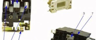
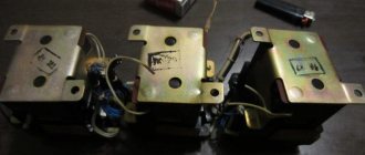
Example of faulty moving contacts that must be replaced
You may be interested in: Radiator brush: dimensions, purpose, application features
The photo above shows a contact that “survived” after a short circuit. The remaining two have failed and need to be replaced.
Repair of contactors and magnetic starters often comes down to repair of contact groups. This is done by cleaning carbon deposits from the contact pad. If shells and build-ups are found during inspection, then these places need to be leveled with a flat, small file or needle file. This is done in the same plane as the contact pad of the fixed contact. To ensure a better effect, you can grind both contact pads on the moving and fixed elements.
It is highly not recommended to do all these operations with sandpaper or sandpaper, since in this case it is very difficult to maintain a flat surface. An unmaintained plane means a decrease in the contact area, and this in turn causes excessive heating and premature failure of the magnetic starter. It is worth inspecting both the main and auxiliary contact groups.
Why is the magnetic starter humming?
Group: Forum Participants Messages: 4886 Registration: 9/20/2006 User No.: 4070
, everything is clear. I don’t understand anything about the chains, don’t cut them, as I understand they are installed inside the contactor, right? Let me tell you, the station worked successfully for about 2 years, no rattling. Maybe there was a bug in the scheme? Look how many auxiliary contacts are involved. By the way, due to the increased voltage, could it be that it is about 250 V (it is produced by a transformer that converts 400 V from 2 phases to 220-230 V)?
Ahhh, that's it. 2. 3 years, dust, humidity. familiar. After disassembling the contactors, a “beard” of scale and small steel filings was sometimes observed on the mangite pipelines. Blowing with compressed air once every six months and a drop of Azmol on the joints of the magnetic circuits helps, yes. The transformer doesn't seem to play much of a piano. although, it wouldn’t hurt, just in case, to check with a dial gauge how the output voltage behaves when the contactors are turned on, just to reassure yourself; Well, it wouldn’t hurt to inspect the contacts either: if there is a little hydrogen sulfide in the air, the contacts turn black and become coated with silver sulfide, yes, yes, but this is not good - the contactors just don’t stick.
Post edited by BROMBA
— 23.6.2010, 16:35
Group: Forum Participants Messages: 1034 Registration: 5/25/2009 From: Zaporozhye User No.: 33943
It looks like the voltage on the coil is too high. Tell me exactly the catalog number of the contactors that are humming, the coil voltage and the actual voltage of the control circuit.
For the experiment, place a resistor in series with the coil to reduce the voltage.
Group: Forum Participants Messages: 387 Registration: 12/8/2006 From: Nizhny Novgorod User No.: 5106
It looks like the voltage on the coil is too high. Tell me exactly the catalog number of the contactors that are humming, the coil voltage and the actual voltage of the control circuit.
For the experiment, place a resistor in series with the coil to reduce the voltage.
Hmmmmmmmmm, I’m almost firmly convinced that this effect comes from increased tension. The tester showed 254 V. Contactor LC1D18M7 (Schneider Electric). What resistor would you recommend installing (value, power). Is it possible to install a common resistor after the step-down transformer for the entire circuit (9 contactors, 3 relays, controller power supply).
Group: Forum Participants Messages: 3846 Registration: 13.2.2008 User No.: 15519
Schneider himself. " of course - gud, only who sharpened (made) them) padi Ketatskie. And so on, a “beard” from metal waste, also a buzz (in “six seconds” it picks up work from a bin).
Resistor, if only to confirm the version - beep; power 2..4 coil power rating (current consumption x voltage).
Post edited by vadim999
— 24.6.2010, 9:58
Group: Moderators Messages: 10134 Registration: 3.7.2004 From: Tomsk User No.: 32
Group: Forum Participants Messages: 387 Registration: 12/8/2006 From: Nizhny Novgorod User No.: 5106
So you can choose a resistor with high power. The power of the contactor coils is known, as is their number. Or, correct me.
Group: Forum Participants Messages: 14839 Registration: 11/28/2008 From: near Samara.. User No.: 26006
twice baptized pioneer
Group: Forum Participants Messages: 4629 Registration: 13.7.2008 From: Novosibirsk User No.: 20580
Good evening!! Maybe I’m stupid, but: 1. 2 fuses (!) on the line burnt out. You can find out their denomination. 2. 7.5 kW WILO - 13-15A at the operating point. Contactor at 9A(.) or did I not understand?? 3. Star/delta starting at 7.5 kW is this an Indian trick or do you use the pump using technology more often than using S1 (the frequency of starts is no more than 10 times/hour)?? Can you tell me the brand of the pump? 4. And lastly: the inserts burn due to current. And how did you imagine the development of super-current with such a switch on?
Killed WILO!! Some people are lucky
Post edited by Usach
— 24.6.2010, 13:14
Group: Forum Participants Messages: 1153 Registration: 14.2.2008 User No.: 15568
twice baptized pioneer
Group: Forum Participants Messages: 4629 Registration: 13.7.2008 From: Novosibirsk User No.: 20580
5. Can you find out the brand and rating of the heat pump 2F4
Group: Forum Participants Messages: 387 Registration: 12/8/2006 From: Nizhny Novgorod User No.: 5106
Good evening!! Maybe I’m stupid, but: 1. 2 fuses (!) on the line burnt out. You can find out their denomination. 2. 7.5 kW WILO - 13-15A at the operating point. Contactor at 9A(.) or did I not understand?? 3. Star/delta starting at 7.5 kW is this an Indian trick or do you use the pump using technology more often than using S1 (the frequency of starts is no more than 10 times/hour)?? Can you tell me the brand of the pump? 4. And lastly: the inserts burn due to current. And how did you imagine the development of super-current with such a switch on?
Killed WILO!! Some people are lucky
1. The fuse rating is 20 A. 2. Yes, the rated current is 14.3 A, the contactor is 9 A, the current flowing through it does not exceed 8 A, since the current flows through 2 contactors (star-delta start, see diagram). 3. No trickery, the Germans did it that way. In general, according to their standard, if the motor power is above 4 kW, star-delta starting is required, or a soft starter, inverter. I don’t remember where I read it. Brand MVI1609-6 (7.5 kW). 4. I don’t know why 2 fuses blew out. Why lucky? WILO is a bad manufacturer, do you think?
Trans, yes, imported. Visually I remember that there are several inputs for several voltages, 400 V, 380 V and some others. And several outputs 230, 125 V, in my opinion. On Friday I'll go and switch the primary winding of the trance from 400 V to 380 V and see what happens. Moreover, Schneider’s technical support also expressed the opinion that the coil is oversaturated and the return spring cannot return it to its original position, which is why the ABB contactors are stuck. The light bulb is in series, this is for artificial resistance, do I understand correctly?
Tags
5АЗМВ DIALux Ex PLC Certification Dielectric boots Explosion safety Galoshes Double-sided switch Grounding Insulated tool Instruction Testing Cable Insulating pliers Rubber carpets Contactor Ladders Operational negotiations Operational log Lighting control gear Dielectric gloves Testing knowledge on electrical safety Loading TRN Inspection of contacts Repair PME SIZ STDP Thermal relay TRN RCD Index Voltage Photo AD 5000 kW Insulating rod Electrical safety Electric motor Electrical clamps Energy saving types of repairs PPR schedule two-way lighting control cable coupling TRN adjustment commissioning transformers
Posts 1 page 10 of 13
Share1Wed, 29 Jun 2011 00:21
- Author: fapsuk
- load
- From: Chelyabinsk
- Registered: Tue, 17 May 2011
- Invitations: 0
- Posts: 12
- Respect: [+0/-0]
- Positive: [+31/-0]
- Gender: Male
- Age: 49 [1972-04-17]
- Spent on the forum: 1 day 10 hours
- Last seen: Thu, 6 Oct 2011 21:48
Good day everyone! Please tell me what to do with the humming contactor KT 6053 C in ShchPTA 380/600. The hum appeared after several emergency outages in the city power grid. Previously, when a hum appeared, you could knock on the core with the handle of a hammer, and it would stop. Now nothing helps. When the contactor is turned off, the diesel engine starts, and the upper group of contacts is energized. You can turn it off only for an hour until the batteries run out.
Share2Wed, 29 Jun 2011 01:13
- Author: Slava
- master
- Registered: Tue, 22 Dec 2009
- Invitations: 0
- Posts: 1234
- Respect: [+72/-14]
- Positive: [+32/-6]
- Gender: Male
- Time spent on the forum: 9 days 22 hours
- Last seen: Thu, 16 Aug 2012 10:10
They forgot to add “do not offer service.” Well, if you are too lazy to clean, lubricate and tighten, I can offer another option - consider it a radio.
Share3Wed, 29 Jun 2011 01:17
- Author: fapsuk
- load
- From: Chelyabinsk
- Registered: Tue, 17 May 2011
- Invitations: 0
- Posts: 12
- Respect: [+0/-0]
- Positive: [+31/-0]
- Gender: Male
- Age: 49 [1972-04-17]
- Spent on the forum: 1 day 10 hours
- Last seen: Thu, 6 Oct 2011 21:48
After all, everything there is under tension, and it would be nice to know what to tighten.
Share4Wed, 29 Jun 2011 01:24
- Author: Slava
- master
- Registered: Tue, 22 Dec 2009
- Invitations: 0
- Posts: 1234
- Respect: [+72/-14]
- Positive: [+32/-6]
- Gender: Male
- Time spent on the forum: 9 days 22 hours
- Last seen: Thu, 16 Aug 2012 10:10
To be completely happy, measure the voltage on the coil - after accidents, the networks will supply reduced power. And to answer what to service there - at least indicate the direct current of the coil or alternating - the brand of the contactor could also help.
Share5Wed, 29 Jun 2011 01:26
- Author: Slava
- master
- Registered: Tue, 22 Dec 2009
- Invitations: 0
- Posts: 1234
- Respect: [+72/-14]
- Positive: [+32/-6]
- Gender: Male
- Time spent on the forum: 9 days 22 hours
- Last seen: Thu, 16 Aug 2012 10:10
Blame - it was the brand. If the voltage is normal, lubricate the mechanics with Tsiatim 201 and look for instructions on those. maintenance of these contactors.
Share6Wed, 29 Jun 2011 01:31
- Author: fapsuk
- load
- From: Chelyabinsk
- Registered: Tue, 17 May 2011
- Invitations: 0
- Posts: 12
- Respect: [+0/-0]
- Positive: [+31/-0]
- Gender: Male
- Age: 49 [1972-04-17]
- Spent on the forum: 1 day 10 hours
- Last seen: Thu, 6 Oct 2011 21:48
I’ll try to convince the management to put the office on zero to service the contactor, but they won’t allow it for a long time, we are category 1 consumers
Share7Wed, 29 Jun 2011 15:23
- Author: Akkomo-T
- power
- From: Kazakhstan
- Registered: Sun, 5 Dec 2010
- Invitations: 0
- Posts: 67
- Respect: [+2/-2]
- Positive: [+15/-4]
- Gender: Male
- Age: 48 [1972-11-04]
- Time spent on the forum: 2 days 11 hours
- Last seen: Wed, 11 Apr 2012 18:25
Look for a short-circuited turn on the magnetic circuit. On contactors it is made of wire in thermosetting insulation. If it burns out, then no amount of cyatim will help. It needs to be restored.
Share8Wed, 29 Jun 2011 16:04
- Author: drug
- energy drink
- From: Astana
- Registered: Wed, 15 Aug 2007
- Invitations: 0
- Posts: 2478
- Respect: [+216/-13]
- Positive: [+38/-9]
- Gender: Male
- Spent on the forum: 1 month 13 days
- Last seen: Fri, 4 Apr 2014 09:50
Look for a short-circuited turn on the magnetic circuit.
If the short-circuit turn is damaged, then the movable semi-magnetic circuit no longer hums, but roars! It is necessary for fapsuk to characterize the nature of the hum (by the way, he previously eliminated the hum by pressing the magnetic circuit, which is more like bad mechanics).
Share9Wed, 29 Jun 2011 22:46
- Author: Gray
- engineer
- From: Ukraine, Zaporozhye
- Registered: Sun, 10 Jun 2007
- Invitations: 0
- Posts: 1949
- Respect: [+142/-38]
- Positive: [+55/-41]
- Gender: Male
- Age: 41 [1980-04-12]
- Time spent on the forum: 13 days 12 hours
- Last seen: Thu, 26 Apr 2012 14:34
management should be persuaded to set the office to zero to service the contactor, but they won’t allow it for a long time, we are category 1 consumers
Why so radical? There is a more acceptable method. Usually the magnetic system rattles, in 15-20 minutes you can slowly disassemble it, wipe it, clean it and put it back together, simultaneously identifying a defective short circuit. coil, debris on the magnetic circuit, loose pressure plates (if any), adjustments. It didn’t help, then you buy a similar device in advance and within an hour it can be replaced. With the dismantled one, also slowly carry out preventive maintenance and find out what’s wrong with it for at least a whole month.
Share10Wed, 29 Jun 2011 23:45
- Author: Slava
- master
- Registered: Tue, 22 Dec 2009
- Invitations: 0
- Posts: 1234
- Respect: [+72/-14]
- Positive: [+32/-6]
- Gender: Male
- Time spent on the forum: 9 days 22 hours
- Last seen: Thu, 16 Aug 2012 10:10
I’ll try to convince the management to put the office on zero to service the contactor, but they won’t allow it for a long time, we are category 1 consumers
For which you will receive a medal, of course. Gray rightly noted , there are well-established and fairly simple ways to carry out maintenance of ATS even for category 1. We used simpler methods than he indicated - direct connection of the second source (if you have category 1, then you have 3 sources - 2 networks and a diesel generator set) - as a rule, to the second network with a load (with the upper contacts of the defective starter de-energized). You can make such a switch (with previously prepared jumpers) in 5-10 minutes, and also back. This gives much more than an hour to repair the contactor - but it is wiser to actually replace it with a new one, and deal with the defective one heartily at your leisure.
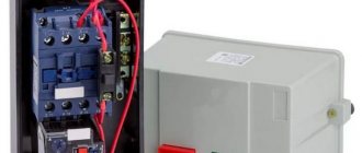
Functional testing and maintenance
To do this, it is necessary to carry out an external inspection of the device.
Pay attention to the condition of the coil. It should not have visible darkening or damage
The contact group should not have any distortions, and the contacts should close simultaneously. Measure the activation and shutdown voltage of the device. The device should operate when the voltage gradually rises from 0 to 0.85 Unom. And turn off when the voltage drops to 0.45 Unom.
In order for the switching device to operate for a long time, it is necessary to carry out maintenance of the device during operation.
To do this, check the status of the connections. Clean the device from dust. Monitor the state of switching contacts. Inspect the metal parts of the device.
Pay special attention to the condition of the spring. She must be pretty tight
The turns are distributed evenly along the entire length. The anchor should not jam or warp.
If there are mechanical faults, lubricate or grind the parts. If the device is equipped with a thermal relay, its performance is checked on a special stand under laboratory conditions.
This test cannot be done at home. If a malfunction is detected, the device is repaired or replaced with a working one.
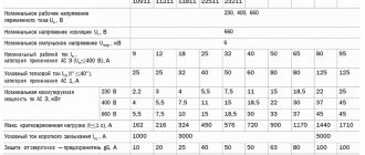
Magnitudes of electromagnetic devices
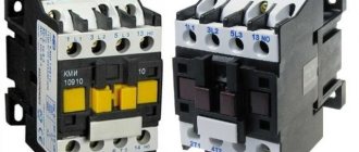
For reliable and uninterrupted operation of electric motors, it is required that the control connection diagram contains a starter with the appropriate characteristics. There are eight sizes of small-sized contactors based on load current.
They are distinguished in this order:
- the zero line contains starters designed for load currents up to 6.3A;
- the first value is for electromagnetic devices with power contacts up to 10A;
- by the second value we must understand that the starter is capable of being used in circuits where Iload = 25A;
- the third position is occupied by small-sized starters for electrical units with Iload = 40A;
- the fourth stage is occupied by starters capable of switching current up to 63A;
- fifth value – for starters for currents up to 100A;
- at the sixth stage there are small-sized contactors for circuits with load currents up to 160A;
- in the seventh position are devices designed for currents up to 250A.
Popular articles How to use an oscilloscope
When calculating the value, it is assumed by default that the magnetic contactor operates at a voltage of 380 V, and also has an AC-3 operating mode according to its parameters.
Principle of operation
Unlike switching contact units, contactors can only carry nominal currents, since they are not intended to interrupt a circuit (for example: a short circuit).
Using an additional current circuit, the device is controlled, passing through an inductive coil with a voltage from 24 to 220-380 volts. In order to increase safety during product operation, the total current value should be slightly lower than the operating current level in the passing circuits. The contactor does not have the mechanical resource to hold the contacts in the active position, therefore, in the absence of a guiding voltage flow on the inductive coil, it opens the circuit. To hold the circuit in the active position, an “auto-catch” system is used using two open contacts (example: using a programmable logic controller).
Contactor circuit
Typically, contactors are used for wiring AC electrical circuits when operating up to 650-660 V and current up to 1500 A.
Purpose of the device
With the help of such devices the following is carried out:
- Turning on or off electric motors of mechanical drives in industrial equipment;
- Management of the external lighting system of populated areas and illumination of historical and industrial facilities;
- When using electric heating, heating elements of heating devices are connected and disconnected;
- With their help, they switch electric motors and other starting elements in automation circuits;
- Switching devices are also widely used in household equipment.
Such devices are available for single-phase or three-phase starters.
Starter or contactor? What is the difference between a starter and a contactor?