Here you will learn:
- When do you need a controller?
- Solar controller functions
- How does the battery charge controller work?
- Device characteristics
- Types
- Selection options
- Controller connection methods
- Homemade controller: features, components
- How can some components be replaced?
- Principle of operation
A solar charge controller is a mandatory element of a solar panel power system, in addition to batteries and the panels themselves. What is it responsible for and how to make it yourself?
When do you need a controller?
Solar energy is so far limited (at the household level) to the creation of photovoltaic panels of relatively low power. But regardless of the design of the photoelectric converter of solar light into current, this device is equipped with a module called a solar battery charge controller.
Indeed, the solar photosynthesis installation includes a rechargeable battery - a storage device for the energy received from the solar panel. It is this secondary energy source that is primarily served by the controller.
Next, we will understand the structure and operating principles of this device, and also talk about how to connect it.
When the battery is at maximum charge, the controller will regulate the current supply to it, reducing it to the required amount to compensate for the self-discharge of the device. If the battery is completely discharged, the controller will turn off any incoming load to the device.
The need for this device can be reduced to the following points:
- Multi-stage battery charging;
- Adjusting the battery on/off when charging/discharging the device;
- Connecting the battery at maximum charge;
- Connecting charging from photocells in automatic mode.
A battery charge controller for solar devices is important because the performance of all its functions in proper mode greatly increases the service life of the built-in battery.
Price
A solar power supply system is assembled primarily to save money, so the price of individual parts is a very important point. The proposed options have stood the test of time and are the optimal combination of price/quality:
- Solar controller 20a – cost $20.75 – simple controls, bright LCD display, clear interface. Does an excellent job of charging the battery. PWM technology. It is possible to connect via USB to a computer for setup.
- MPPT Tracer 2210RN Solar Charge Controller Regulator, price $75 – 20A MTTP controller – high-quality and reliable, certified, recognizes day/night. High efficiency – 97%
Sources used:
sovet-ingenera.com, energo.house, electric-220.ru, alter220.ru, masterclub.online, electricadom.com
Solar controller functions
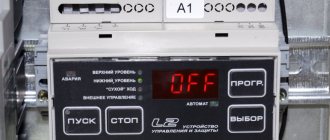
An electronic module called a solar controller is designed to perform a number of control functions during the charging/discharging process of a solar battery.
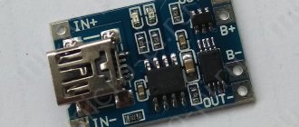
This is what one of the many existing models of charge controllers for a solar battery looks like. This module is one of the PWM type developments
When sunlight falls on the surface of a solar panel installed, for example, on the roof of a house, the device's photocells convert this light into electric current.
The resulting energy, in fact, could be supplied directly to the storage battery. However, the process of charging/discharging a battery has its own subtleties (certain levels of currents and voltages). If you neglect these subtleties, the battery will simply fail in a short period of operation.
To avoid such sad consequences, a module called a charge controller for a solar battery is designed.
In addition to monitoring the battery charge level, the module also monitors energy consumption. Depending on the degree of discharge, the solar battery charge controller circuit regulates and sets the current level required for the initial and subsequent charge.
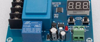
Depending on the power of the solar battery charge controller, the designs of these devices can have very different configurations
In general, in simple terms, the module provides a carefree “life” for the battery, which periodically accumulates and releases energy to consumer devices.
Assembly, tilt angle
We will briefly describe the installation itself, how to connect solar panels, since fastenings and other nuances are also separate topics.
Installation consists of fastening the panels to the frame; there are several types of fasteners and brackets: on slate, on metal, tiles, hidden on the roof sheathing. Support rails, clamps, clamps (end and central) guides are purchased or included in the kit for the selected installation option.
The connecting butt elements create a frame from fixing slats. Terminal elements and conductor holders are also used - they combine aluminum frames and ground them, fixing cables.
If installation is carried out on a roof with a slope, then the optimal angle for panels is 30... 40° in northern latitudes, for example, 45°. In general, for self-cleaning of modules by rain, the angle should be at least 15°.
These positions are created with support profiles, often making a convenient, collapsible, adjustable, rotating structure.
When the array is illuminated unevenly, the panel in a brighter place produces more current, which is partially spent on heating the less loaded solar panels. To eliminate this phenomenon, cut-off diodes are used, soldered between the planes from the inside.
How does the battery charge controller work?
In the absence of sunlight on the solar cells of the structure, it is in sleep mode. After the rays appear on the elements, the controller is still in sleep mode. It turns on only if the accumulated energy from the sun reaches 10 V in electrical equivalent.
As soon as the voltage reaches this value, the device will turn on and begin supplying current to the battery through the Schottky diode. The process of charging the battery in this mode will continue until the voltage received by the controller reaches 14 V. If this happens, then some changes will occur in the controller circuit for a 35-watt solar battery or any other. The amplifier will open access to the MOSFET transistor, and the other two, weaker ones, will be closed.
This will stop charging the battery. As soon as the voltage drops, the circuit will return to its original position and charging will continue. The time allotted to the controller to perform this operation is about 3 seconds.
Average prices
In order to understand the price range of MPPT controllers from various manufacturers, you can consider the cost of the models given above, these are:
- IES 100/20 MPPT – from 10,000.00 rubles;
- IES DOMINATOR MPPT 250/60 – from 40,000.00 rubles;
- Epsolar MPPT TRACER-2215BN 20A 12/24V – from 9000.00 rubles;
- IT6415ND 60A 12V/24V/36 V – from 30,000.00 rubles.
- Victron BlueSolar 100/15 12/24V 15A – from 11,000.00 rubles;
- Victron BlueSolar 150/70 12/24/48V 70A – from 55,000.00 rubles.
As can be seen from the above figures, the cheapest are models made in China, and the most expensive are from European manufacturers.
Products from domestic enterprises are somewhat more expensive than devices manufactured in China, but cheaper than those manufactured in Europe.
Device characteristics
Low power consumption in idle mode. The circuit was designed for small to medium-sized lead-acid batteries and consumes low current (5 mA) when idle. This increases the lifespan of the batteries.
Easily accessible components. The device uses regular components (not SMD), which can be easily found in stores. There is no need to flash anything, the only thing you will need is a voltmeter and an adjustable power supply to configure the circuit.
Latest version of the device. This is already the third version of the device, so most of the errors and shortcomings that were present in previous versions of the charger have been corrected.
Voltage adjustment. The device uses a parallel voltage stabilizer to ensure that the battery voltage does not exceed the norm, usually 13.8 Volts.
Undervoltage protection. Most solar chargers use a Schottky diode to protect against battery current leakage to the solar panel. A shunt voltage stabilizer is used when the battery is fully charged. One of the problems with this approach is losses on the diode and, as a consequence, its heating. For example, a 100 Watt, 12V solar panel supplies 8A to the battery, the voltage drop across the Schottky diode will be 0.4V, i.e. power dissipation will be about 3.2 watts. Firstly, this is a loss, and secondly, the diode will need a radiator to remove heat. The problem is that it will not be possible to reduce the voltage drop; several diodes connected in parallel will reduce the current, but the voltage drop will remain the same. In the circuit presented below, mosfets are used instead of conventional diodes, therefore power is lost only through active resistance (resistive losses).
For comparison, in a 100 W panel using IRFZ48 (KP741A) mosfets, the power loss is only 0.5 Watt (at Q2). This means less heat and more energy for the batteries. Another important point is that mosfets have a positive temperature coefficient and can be connected in parallel to reduce the on-resistance.
The above scheme uses a couple of non-standard solutions.
Charger. There is no diode between the solar panel and the load, instead there is a Q2 mosfet. The diode in the mosfet allows current to flow from the panel to the load. If a significant voltage appears on Q2, then transistor Q3 opens, capacitor C4 charges, which causes op-amps U2c and U3b to open mosfet Q2. Now, the voltage drop is calculated using Ohm's law, i.e. I*R, and it is much less than if there was a diode there. Capacitor C4 is periodically discharged through resistor R7, and Q2 closes. If current flows from the panel, then the self-inductive emf of inductor L1 immediately forces Q3 to open. This happens very often (many times per second). In the case when current flows to the solar panel, Q2 closes, but Q3 does not open, because diode D2 limits the self-induction EMF of inductor L1. Diode D2 can be designed for a current of 1A, but during testing it turned out that such a current rarely occurs.
Trimmer VR1 sets the maximum voltage. When the voltage exceeds 13.8V, the operational amplifier U2d opens mosfet Q1 and the output from the panel is “shorted” to ground. In addition, op-amp U3b disables Q2, etc. the panel is disconnected from the load. This is necessary because Q1, in addition to the solar panel, short-circuits the load and the battery.
Control of N-channel mosfets. To drive mosfets Q2 and Q4, more voltage is required than that used in the circuit. To do this, op-amp U2 with a string of diodes and capacitors creates an increased voltage VH. This voltage is used to power U3, whose output will be increased voltage. The combination of U2b and D10 ensures the stability of the output voltage at 24 Volts. At this voltage, the voltage through the gate-source of the transistor will be at least 10V, so the heat generation will be small. Typically, N-channel mosfets have much lower resistance than P-channel ones, which is why they were used in this circuit.
Undervoltage protection. Mosfet Q4, operational amplifier U3a with external wiring of resistors and capacitors, are designed for protection against low voltage. Here Q4 is used non-standard. The mosfet diode ensures a constant flow of current into the battery. When the voltage is above the set minimum, the mosfet is open, allowing a small voltage drop when charging the battery, but more importantly, it allows current to flow from the battery to the load if the solar panel cannot provide sufficient power output. The fuse protects against short circuits on the load side.
Below are pictures of the arrangement of elements and printed circuit boards.
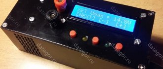
Device setup. During normal use of the device, jumper J1 should not be inserted! LED D11 is used for tuning. To configure the device, connect an regulated power supply to the “load” terminals.
Installing undervoltage protection Insert jumper J1. In the power supply, set the output voltage to 10.5V. Rotate trimming resistor VR2 counterclockwise until LED D11 lights up. Turn VR2 slightly clockwise until the LED goes out. Remove jumper J1.
Setting the maximum voltage In the power supply, set the output voltage to 13.8V. Rotate trimming resistor VR1 clockwise until LED D9 goes out. Slowly turn VR1 counterclockwise until LED D9 lights up.
The controller is configured. Don't forget to remove jumper J1!
If the power of the entire system is small, then the mosfets can be replaced with cheaper IRFZ34. And if the system is more powerful, the mosfets can be replaced with more powerful IRFZ48.
Inverter
Methods for connecting solar panels may be different, but the selection of parameters for parts of the system has general principles. Let's look at how to choose an inverter for different types of solar power plants.
The power plant is completely autonomous. Such a system is not connected to the Energosbyt network (external highway), the user receives all electricity only from the panels. An off-grid inverter will do. These autonomous models can be single or three-phase, capable of converting direct currents of different voltages 12, 24, 48, 96 V and higher. These products are the cheapest ($25–600), but this does not mean they are ineffective - they are suitable for a not particularly demanding assembly of this type; there is no point in taking more expensive products, since their potential will not be used.
Scheme with connection to the central network. SES operates both autonomously and in conjunction with the main highway. But without batteries. An on-grid inverter is suitable here:
- regulates the intake of electricity, but not from the battery, but from the Energosbyt network, if the modules do not produce enough of it;
- sends excess produced energy to the central grid, for example, for sale “at feed-in tariffs”.
The cost of an on-grid product is $200–20,000. Depends on the power of a particular model, for example, for a 3–6 kW device - $2000, for a 1000 kW device - $15,000 and above. 5 kW is enough for a home.
Battery-grid SES is the most common optimal type: energy is generated to power appliances at home, the excess is accumulated in batteries, which release charge at night and/or when the modules cannot cope with the load, as well as into the central network for sale. If the system cannot cope with the load due to increased demands, then it is assumed that energy will be taken from the Energosbyt main line. For such conditions, a hybrid model (with network functions) is suitable. Prices start at $500–$600 and go up to around $20,000.
Other parameters
Below is a brief selection of an inverter based on other criteria that must be taken into account before connecting the solar panel.
| Parameter | Description |
| Power | Depends on the power rating of the solar power plant associated with the DC side and the maximum load on the AC side. It is necessary to take the full value of the SES power (permissible error 90–120%) and the power of all devices when they are turned on simultaneously. The first characteristic is indicated in the TD of the panels; according to the second, it is not just kW that is calculated, but the total peak (starting) value, which can exceed the operating value by 5–7 times. Due to overload during startup, even for 2–3 seconds. the inverter will not start. |
| By voltage | Recommended ratio (voltage/power of SES):
|
| Efficiency | This is an insignificant parameter - all modern products have 90–95% efficiency. The energy consumption of the device should not be more than 5–10% of the energy passing through it. |
| Weight | 1 kg - 100 W. A high-quality device cannot be light, since the more powerful it is, the larger the transformer and its copper windings are. |
| Square wave, sinusoidal signal types | Meander (rectangular shape) - cheap, will not completely protect against power surges. It has a bad effect on inductive loads, for example, on a compressor, air conditioning pumps, and washing machines. Additional stabilizers are installed on it. A pure sine wave is an expensive product, the oscillations are very smooth, only this model is recommended without reservation for a private home for powering the above and all other devices. Quasi-sinusoid - a compromise is applied here, roughly speaking, an imitation of a pure sine wave, suitable for the same purposes as in the previous paragraph, the device is of lower quality, but cheaper. |
| 1 or 3 phase | Three-phase can be installed on both 1 and 3-phase networks. Single-phase - only for the same system. |
Number of inverters
Theoretically, 1 device, if it is selected correctly for the power and other parameters, will be enough for the entire solar power plant. But with a large number of plates in several lines, it is advisable to install its own inverter on each one. The reason is that the instability of one branch (located just below the illuminated side) negatively affects the overall inverter, the efficiency will decrease. And with individual such devices, this disadvantage is leveled out.
A good option is a model for several separate MPPT inputs (2–4 or more). But the price of such equipment is often unreasonably high.
Types
On/Off
This type of device is considered the simplest and cheapest. Its only and main task is to turn off the charge supply to the battery when the maximum voltage is reached to prevent overheating.
However, this type has a certain disadvantage, which is that it switches off too early. After reaching the maximum current, you need to maintain the charging process for a couple more hours, and this controller will immediately turn it off.
As a result, the battery charge will be around 70% of the maximum. This has a negative impact on the battery.
PWM
This type is an improved On/Off. The modernization lies in the fact that it has a built-in pulse width modulation (PWM) system. This function allowed the controller, when the maximum voltage was reached, not to turn off the current supply, but to reduce its strength.
Because of this, it became possible to charge the device almost 100%.
MRRT
This type is considered the most advanced at present. The essence of its work is based on the fact that it is able to determine the exact value of the maximum voltage for a given battery. It continuously monitors the current and voltage in the system. Due to the constant acquisition of these parameters, the processor is able to maintain the most optimal current and voltage values, which allows it to create maximum power.
If we compare the MPPT and PWN controllers, the efficiency of the former is approximately 20-35% higher.
Pulse width modulator
MPPT controller is an electricity control module that is used to generate energy in solar power plants. The device microcircuit operates with maximum efficiency values and gives high output values. The microcircuit that includes a controller of this type is quite complex and includes a number of devices that build the necessary control order. This sequence allows voltage and current levels to be controlled continuously while delivering maximum device output power. The main difference in the configuration of a pulse-width modulator from PWM devices is that they are able to activate their solar module under weather conditions. Thus, the power will be maximum in any weather, regardless of the duration of exposure to the sun.
Selection options
There are only two selection criteria:
- The first and very important point is the incoming voltage. The maximum of this indicator should be higher by approximately 20% of the no-load voltage of the solar battery.
- The second criterion is the rated current. If the PWN type is selected, then its rated current should be higher than the short circuit current of the battery by approximately 10%. If MPPT is selected, then its main characteristic is power. This parameter must be greater than the voltage of the entire system multiplied by the rated current of the system. For calculations, the voltage is taken when the batteries are discharged.
Producing countries
There are many charge controllers on the market with various modifications, differing in both price and quality. Among Russian-made controllers, the best options are the following manufacturers: Emicon, Avtomatika-s, Aries. These companies have been on the controller market for many years and have proven themselves well. Among foreign-made controllers, the leaders are considered to be Allen-Bradley, MicroLogix (a subsidiary of Allen Bradley) and SLC 500. The main criterion for choosing these manufacturers is a large scope of application, i.e. controllers from these companies can be used in different areas and for different purposes.
Foreign-made controllers MicroLogix
Controller connection methods
Considering the topic of connections, it should immediately be noted: for the installation of each individual device, a characteristic feature is working with a specific series of solar panels.
So, for example, if a controller is used that is designed for a maximum input voltage of 100 volts, a series of solar panels should output a voltage no greater than this value.
Any solar power installation operates according to the rule of balancing the output and input voltages of the first stage. The upper limit of the controller voltage must correspond to the upper limit of the panel voltage
Before connecting the device, you need to decide on the location of its physical installation. According to the rules, the installation location should be chosen in dry, well-ventilated areas. Avoid the presence of flammable materials near the device.
The presence of sources of vibration, heat and humidity in the immediate vicinity of the device is unacceptable. The installation site must be protected from precipitation and direct sunlight.
Connection technology for PWM models
Almost all manufacturers of PWM controllers require that the devices be connected in the exact sequence.
The technique of connecting PWM controllers to peripheral devices is not particularly difficult. Each board is equipped with labeled terminals. Here you simply need to follow the sequence of actions
Peripheral devices must be connected in full accordance with the designations of the contact terminals:
- Connect the battery wires to the battery terminals of the device in accordance with the indicated polarity.
- Switch on the protective fuse directly at the point of contact of the positive wire.
- Attach the conductors coming from the solar panel battery to the controller contacts intended for the solar panel. Observe polarity.
- Connect a test lamp of the appropriate voltage (usually 12/24V) to the load terminals of the device.
The specified sequence must not be violated. For example, connecting solar panels first when the battery is not connected is strictly prohibited. By doing this, the user runs the risk of “burning” the device. This material describes in more detail the assembly diagram of solar panels with a battery.
Also, for PWM series controllers, it is not permissible to connect a voltage inverter to the controller load terminals. The inverter should be connected directly to the battery terminals.
Procedure for connecting MPPT devices
The general physical installation requirements for this type of device do not differ from previous systems. But the technological setup is often somewhat different, since MPPT controllers are often considered more powerful devices.
For controllers designed for high power levels, it is recommended to use large cross-section cables equipped with metal end caps for power circuit connections.
For example, for powerful systems, these requirements are supplemented by the fact that manufacturers recommend using a cable for power connection lines designed for a current density of at least 4 A/mm2. That is, for example, for a controller with a current of 60 A, you need a cable to connect to the battery with a cross-section of at least 20 mm2.
Connecting cables must be equipped with copper lugs, tightly crimped with a special tool. The negative terminals of the solar panel and battery must be equipped with adapters with fuses and switches.
This approach eliminates energy losses and ensures safe operation of the installation.
Block diagram of connecting a powerful MPPT controller: 1 – solar panel; 2 – MPPT controller; 3 – terminal block; 4.5 – fuses; 6 – controller power switch; 7.8 – earth bus
Before connecting solar panels to the device, you should make sure that the voltage at the terminals is equal to or less than the voltage that can be supplied to the controller input.
Connecting peripherals to the MTTP device:
- Switch the panel and battery switches to the “off” position.
- Remove the protective fuses on the panel and battery.
- Connect the battery terminals with a cable to the controller terminals for the battery.
- Connect the terminals of the solar panel with a cable to the controller terminals indicated by the corresponding sign.
- Connect the ground terminal to the ground bus with a cable.
- Install the temperature sensor on the controller according to the instructions.
After these steps, you need to reinsert the previously removed battery fuse and turn the switch to the “on” position. A battery detection signal will appear on the controller screen.
Next, after a short pause (1-2 minutes), replace the previously removed solar panel fuse and turn the panel switch to the “on” position.
The device screen will show the voltage value of the solar panel. This moment indicates the successful launch of the solar energy installation.
Instructions for use
Before studying the instructions for using the controller, you need to remember three parameters that must be observed when operating these electronic devices, these are:
- The input voltage of the device should be 15 - 20% higher than the open circuit voltage of the solar panel.
- For PWM (PWM) devices, the rated current must exceed by 10% the short circuit current in the lines connecting energy sources.
- MPPT - the controller must match the system power, plus 20% of this value.
To successfully operate the device, you must study the operating instructions, which are always included with such electronic devices.
The instruction informs the consumer about the following:
Safety requirements - this section defines the conditions under which operation of the device will not lead to electric shock or other negative consequences to the consumer.
Here are the main ones:
- Before installing and configuring the controller, it is necessary to disconnect the solar panels and batteries from the device using switching devices;
- Prevent water from entering the electronic device;
- The contact connections must be tightly tightened to avoid heating them during operation.
- Technical characteristics of the device - this section allows you to select a device according to the requirements for it in a specific circuit and installation location.
Typically this is:
- Types of adjustments and settings of the device;
- Operating modes of the device;
- The control and display elements of the device are described.
- Methods and place of installation - each controller is mounted in accordance with the requirements of the manufacturer, which allows you to operate the device for a long time and with guaranteed quality.
Information is provided on:
- The location and spatial placement of the device;
- The overall dimensions of utility networks and devices, as well as elements of building structures, are indicated in relation to the mounted device;
- Installation dimensions are given for the mounting locations of the device.
- Methods of inclusion in the system - this section explains to the consumer which terminal and how the connection should be made in order to put the electronic device into operation.
Reported:
- In what sequence should the device be connected to the operating circuit?
- Inadmissible actions and measures when turning on the device are indicated.
- Setting up the device is an important operation on which the operation of the entire solar power plant circuit and its reliability depend.
This section tells you how to:
- What indicators and how do they signal the operating mode of the device and its malfunctions;
- Information is provided on how to configure the desired operating mode of the device by time of day, load conditions and other parameters.
- Types of protection – this section tells you which emergency modes the device is protected from.
Alternatively it could be:
- Protection against short circuit in the line connecting the device to the solar panel;
- Overload protection;
- Protection against short circuit in the line connecting the device to the battery;
- Incorrect connection of solar panels (reverse polarity);
- Incorrect battery connection (reverse polarity);
- Protection against device overheating;
- Protection against high voltage caused by thunderstorms or other atmospheric phenomena.
- Errors and malfunctions - this section explains what to do if for some reason the device does not work correctly, or does not work at all.
The connection is considered: malfunction - possible cause of the malfunction - method of eliminating the malfunction.
- Checking and maintenance – this section provides information on what preventive measures need to be taken to ensure trouble-free operation of the device.
- Warranty - indicates the period during which the device can be repaired at the expense of the device manufacturer, subject to proper operation, in accordance with the operating instructions.
Homemade controller: features, components
The device is designed to work with only one solar panel, which creates a current of no more than 4 A. The capacity of the battery, the charging of which is controlled by the controller, is 3,000 A*h.
To manufacture the controller, you need to prepare the following elements:
- 2 microcircuits: LM385-2.5 and TLC271 (is an operational amplifier);
- 3 capacitors: C1 and C2 are low-power, have 100n; C3 has a capacity of 1000u, designed for 16 V;
- 1 indicator LED (D1);
- 1 Schottky diode;
- 1 SB540 diode. Instead, you can use any diode, the main thing is that it can withstand the maximum current of the solar battery;
- 3 transistors: BUZ11 (Q1), BC548 (Q2), BC556 (Q3);
- 10 resistors (R1 – 1k5, R2 – 100, R3 – 68k, R4 and R5 – 10k, R6 – 220k, R7 – 100k, R8 – 92k, R9 – 10k, R10 – 92k). They can all be 5%. If you want greater accuracy, you can use 1% resistors.
How can some components be replaced?
Any of these elements can be replaced. When installing other circuits, you need to think about changing the capacitance of capacitor C2 and selecting the bias of transistor Q3.
Instead of a MOSFET transistor, you can install any other one. The element must have low open channel resistance. It is better not to replace the Schottky diode. You can install a regular diode, but it must be placed correctly.
Resistors R8, R10 are equal to 92 kOhm. This value is non-standard. Because of this, such resistors are difficult to find. Their full replacement can be two resistors with 82 and 10 kOhm. They must be turned on sequentially.
If the controller will not be used in an aggressive environment, you can install a trimming resistor. It allows you to control the voltage. It will not work for long in an aggressive environment.
If you need to use a controller for more powerful panels, you need to replace the MOSFET transistor and diode with more powerful analogues. All other components do not need to be changed. There is no point in installing a heatsink to regulate 4A. By installing a MOSFET on a suitable heatsink, the device will be able to work with a more efficient panel.
Principle of operation
If there is no current from the solar battery, the controller is in sleep mode. It doesn't use a single watt from the battery. After sunlight hits the panel, electric current begins to flow to the controller. It should turn on. However, the indicator LED along with 2 weak transistors turns on only when the current voltage reaches 10 V.
Once this voltage is reached, current will flow through the Schottky diode to the battery. If the voltage rises to 14 V, amplifier U1 will start working, which will open the MOSFET transistor. As a result, the LED will go out and two low-power transistors will close. The battery will not charge. At this time, C2 will be discharged. On average this takes 3 seconds. After capacitor C2 discharges, the hysteresis of U1 will be overcome, the MOSFET will close, and the battery will begin to charge. Charging will continue until the voltage rises to the switching level.
Charging occurs periodically. Moreover, its duration depends on the charging current of the battery and how powerful the devices connected to it are. Charging continues until the voltage reaches 14 V.
The circuit turns on in a very short time. Its activation is influenced by the charging time of C2 with current, which limits transistor Q3. The current cannot be more than 40 mA.
Varieties
Today there are several types of charge controllers. Let's look at some of them.
MPPT controller
This abbreviation stands for Maximum Power Point Tracking, that is, monitoring or tracking the point where power is maximum. Such devices are capable of lowering the voltage of the solar battery to the voltage of the battery. In this situation, the current strength in the solar battery decreases, as a result of which the cross-section of the wires can be reduced and the design reduced in cost. Also, using this controller allows you to charge the battery when there is not enough sunlight, for example, in bad weather conditions or in the early morning and evening. It is the most common due to its versatility. Used for serial connection. The MPPT controller has a fairly wide range of settings, which ensures the most efficient charging.
Device characteristics:
- The cost of such devices is high, but it pays off when using solar panels over 1000 W.
- The total input voltage to the controller can reach 200 V, which means that several solar panels can be connected in series to the controller, on average up to 5. In cloudy weather, the total voltage of the series-connected panels remains high, which ensures an uninterrupted supply of electricity.
- This controller can operate with non-standard voltage, for example, 28 V.
- The efficiency of MPPT controllers reaches 98%, which means that almost all solar energy is converted into electrical energy.
- Possibility of connecting batteries of various types, such as lead, lithium iron phosphate and others.
- The maximum charge current is 100 A; at this current value, the maximum power output by the controller can reach 11 kW.
- Basically, all models of MPPT controllers are capable of operating at temperatures from -40 to 60 degrees.
- To start charging the battery, a minimum voltage of 5 V is required.
- Some models have the ability to simultaneously work with a hybrid inverter.
Controllers of this type can be used both in commercial enterprises and in country houses, since there are various models with different indicators. For a country house, an MPPT controller with a maximum power of 3.2 kW and a maximum input voltage of 100 V is suitable. In large volumes, much more powerful controllers are used.
PWM controller
The technology of this device is simpler than MPPT. The principle of operation of such a device is that while the battery voltage is below the limit of 14.4 V, the solar battery is connected to the battery almost directly, and the charge occurs quite quickly; after the value is reached, the controller will lower the battery voltage to 13 .7 V, as a result of which the battery will be fully charged.
Device characteristics:
- Input voltage no more than 140 V.
- Works with 12 and 24 V solar panels.
- The efficiency is almost 100%.
- Ability to work with many different types of batteries.
- The maximum input current reaches 60 A.
- Operating temperature from –25 to 55 ºC.
- Possibility to charge the battery from scratch.
Thus, PWM controllers are used most often when the load is not very large and solar energy is sufficient. Such devices are more suitable for owners of small country houses where low-power solar panels are installed.
The MPPT controller, as mentioned above, is the most popular today because it has high efficiency and is capable of operating even in conditions of lack of sunlight. The MPPT controller is also capable of operating at higher powers, ideal for a large country house. However, when choosing a specific type, you need to take into account the amount of input and output current, as well as the degree of power and voltage ratings.
Installing an MPPT controller in small areas is impractical, since it will not pay for itself. If the total voltage of the solar battery is more than 140 V, then an MPPT controller should be used. PWM controllers are the most affordable, as their price starts from 800 rubles. There are models for 10 thousand, when the cost of an MPPT controller is approximately 25 thousand.