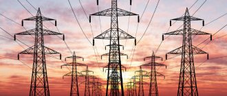
A substation (SS) is an installation that converts electricity and distributes it among consumers. Depending on its purpose, it lowers or increases the output voltage. Before you start building a substation, you need to understand its types and features.
Substation Substation
Source:
https://elektroportal.ru/
Purpose of the electrical substation
The main purpose of the substation is to organize energy supply. It receives and distributes electricity to consumers with the required current parameter, and also simplifies the management and maintenance of the power system.
Most often, electrical networks are divided into areas with their own transformer substations, to which they attach their own dispatch and repair services. Therefore, an electrical installation is an important component of the energy supply system, which simultaneously solves several problems:
- reduces power loss;
- guarantees constant voltage to the consumer;
- carries out deep injection of high voltage into the load center.
The substation consists of:
- distribution devices;
- transformers;
- control modules;
- auxiliary devices for protection and control.
Installation is carried out according to approved projects in stages. Depending on the nominal power value and type, the substation can be a compact or large-scale structure.
Installation of power lines (power lines) with voltages above 1000 V
INSTALLATION OF POWER LINES WITH VOLTAGES ABOVE 1000 V
1 AREA OF USE
A typical technological map has been developed for the installation of power lines (power lines) with voltages exceeding 1000 V.
General information
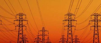
Overhead power lines with voltages above 1000 V
Electrical networks located in open areas outside buildings are often carried out using overhead lines
(VL).
as the length of the overhead line span
on the ground.
The anchor section
is the sum of the span lengths between anchor-type supports (Fig. 1).
By
wire
sag f,
with the same height of the suspension points, we mean the vertical distance between the line connecting the wire suspension points and the lowest point of the wire. The dimension of line H is taken to be the smallest vertical distance with the greatest sag of the wires to the ground level or intersecting structures.
Fig.1. Main characteristics of the line in span
Route turning angle
lines is the angle between the directions of the line in adjacent spans. Wire tension refers to the force directed along the axis of the wire. The mechanical stress of a wire is obtained by dividing the tension by the cross-sectional area of the wire.
Intermediate supports
installed on straight sections of the overhead line route. Under normal operating conditions, these supports should not absorb forces directed along the overhead line.
Corner supports
installed in places where the direction of the overhead line route changes. Under normal operating conditions, these supports must withstand the tension component of the wires of adjacent spans.
Anchor supports
installed at intersections with various structures, as well as in places where the number, grades and cross-sections of wires change. In normal operating conditions, these supports must absorb forces from the difference in tension of the wires directed along the overhead line. Anchor supports must have a rigid structure.
End supports
installed at the beginning and end of overhead lines, as well as in places limiting cable inserts. They are anchor-type supports and must withstand one-sided tension of wires in normal operating modes of overhead lines.
Branch supports
installed at branches from overhead lines.
Cross supports
installed at the intersection of overhead lines of two directions.
Intermediate span -
this is the horizontal distance between two adjacent intermediate supports. As a rule, these spans on overhead lines up to 1 kV range from 30-50 m, and on overhead lines above 1 kV - 100-250 m or more.
Overhead lines have the following structural elements: wires, supports, insulators, fittings for fastening wires to insulators and insulators to supports. Overhead lines can be single or double circuit. One circuit means three wires of one three-phase line or two wires of one single-phase line. For overhead lines with voltages up to 10 kV, aluminum, steel-aluminum and steel wires are used. Supports for overhead lines with voltages up to 10 kV are made of wood and reinforced concrete. Wooden supports are easy to make and cheap, but are short-lived due to wood rotting. Reinforced concrete supports are more expensive, but stronger.
Wooden intermediate (Fig. 2, a) and corner anchor (Fig. 2, b) supports are widely used in the construction of overhead lines in I; II and III climatic regions for ice. The vertical distances between wires on these overhead lines are 400 mm.
Fig.2. Wooden intermediate overhead line supports (a) and corner anchor supports (b)
In climatic region IV, when there is ice, the distance between wires on overhead lines constructed using these supports should be 600 mm. In the manufacture of parts for wooden supports, softwood timber is used. The main types of reinforced concrete supports used on 6-10 kV overhead lines are shown in Fig. 3, a-d.
Fig.3. Reinforced concrete supports of 6-10 kV overhead lines:
A -
intermediate P-10;
b -
anchor A-10;
c —
end KA-10;
g -
angular for an angle of 90° ULA-10
Reinforced concrete supports are made by vibration or centrifugation. Vibration bearings can be round, rectangular or I-beam. The steel reinforcement of reinforced concrete supports can be unstressed, stressed or partially stressed.
Intermediate supports are single-column with horizontal wires mounted on ShS-10 pin insulators. Anchor, corner, end, branch supports are constructed from racks of intermediate supports. Metal fastening and bracing parts are used. The supports are designed for hanging wires of grades A25-A70, AS16-AS50 and PS25. The height of the pin is taken to be increased to 175 mm. The pins are grounded by welding to the outlets of the reinforced concrete cross-beam.
On overhead lines up to 10 kV, pin insulators are widely used (Fig. 4, a-d
).
Fig.4. Pin insulators:
A -
TF;
b -
ShS-6;
c —
ShF-10V;
g -
ShF-10G for overhead line-10 kV
Insulators are delivered for installation in lattice boxes. Rejection of insulators is carried out visually before sending them to the track. The manufacturer supplies each batch of insulators with a document certifying their quality.
Installation of wooden and reinforced concrete supports for overhead lines up to 10 kV
. Single-column supports, as a rule, are installed using drilling crane machines BM, BKM and others immediately after drilling pits. The machine is positioned at a distance of about 0.5 m from the edge of the pit, the outriggers (outriggers) are lowered, the winch traction cable is released, the universal sling is attached at a distance of 1-1.5 m above the center of gravity of the stand, and secured 2.5-3 m from at the bottom end, rope guys lift (hang) the support above the pit and, guiding its butt with guys, lower it into the pit. During the descent of the support, it is deployed so that the traverses or hooks are perpendicular to the axis of the overhead line. Then they pour a little soil into the pit, straighten and check the support, fill the pit completely with soil, tamping it layer by layer, and remove the sling. In addition, to install such supports, you can use a crane, an MMTS-2 machine with a slingless hydraulic grip, or an RMTS-3 unrolling and hanging machine, etc.
A-shaped supports are installed using truck or tractor cranes, since the lifting capacity of drill crane machines is insufficient. The support is lifted with a two-legged sling, hooking it to the upper part of the support (wooden - above the crossbar, reinforced concrete - just below the crossbeam). To avoid skewing, both branches of the sling are secured at an equal distance from the top of the support.
If the lifting height of the crane hook is sufficient, the support is installed in a pre-opened pit in the same way as a single-post one. If the lifting height of the hook is not enough, the support is first laid out so that the ends of the racks are at the edges of the pits. When lifting the support with a cargo hook, the butts of the racks slide into the pit along boards that are pre-installed as guides in the upper part of the pit and at the same time protecting its walls from destruction. After lifting the hook to the top point, bring the support to a vertical position by moving the crane boom.
Supports with struts are installed using drill crane machines. First, the support post is lowered into one pit and its base is sprinkled with soil. Then they lift the strut, lower its lower end into another pit, and bring the upper end to the rack and, holding it with a hook, secure it with bolts or special brackets. After installation, the support is straightened, aligned, the pit is filled with soil and the slings are removed.
Installation of single-column wooden and reinforced concrete supports of 35-220 kV overhead lines using a crane
. The relatively large mass and height of single-column wooden and reinforced concrete supports of 35-220 kV overhead lines do not allow the use of drill crane machines for their installation. Therefore, such supports (Fig. 5) are lifted by cranes SMK-10, K-162 and others of appropriate lifting capacity. The assembled support 2 is lifted by a crane and lowered into the pit 4 in the same way as the supports of overhead lines up to 10 kV. The upper crossbars are usually secured after installing the support, for which they dig a special trench, lay the crossbar in it with a crane and secure it to the stand with clamps. Then the support is aligned and the foundation pit is filled.
Fig.5. Installation of a single-post wooden (reinforced concrete) support for a 35-220 kV overhead line using a crane:
a - laying out, b - lifting and lowering into the pit; 1 - crane boom, 2 - support, 3 - guy, 4 - foundation pit
Similarly, intermediate U-shaped wooden supports of 35-110 kV overhead lines weighing up to 2.5 tons are installed.
When lifting single-column reinforced concrete supports 1 with the K-LEP-7 installation crane (Fig. 6), they are laid out along the axis of the overhead line so that the lower end of the rack is at a distance of 1.5 m from the center of the pit 3. Crane 2 with a raised boom is brought to the support from the end and installed on outriggers 4. The extended telescopic boom is lowered onto the stand and secured to it at two points. Then the boom along with the support is raised to a vertical position, the support is lowered into the pit, straightened and covered with soil.
Fig.6. Installation of a single-column reinforced concrete support for a 35-220 kV overhead line using a K-LEP-7 installation crane:
1 — support, 2 — crane, 3 — pit, 4 — outriggers (outriggers); I and II - support positions when lifting
Installation of single-column reinforced concrete supports of 35-220 kV overhead lines using a crane and tractor
(Fig. 7). If it is impossible to install the support with one crane (for example, in soft soils, where the pit is being excavated with an excavator and the crane cannot come close), the assembled support 1 is laid out along the axis of the line above the dug pit 8 so that the lower end of the stand is at a distance of 1.5-2 m from the edge of the pit (position /). Crane 4 is installed across the axis of the overhead line on outriggers at a distance of 0.5-1 m from the center of gravity of the support on the edge of the pit under the lower traverse of the support, two side braces 3 are attached from a cable about 50 m long and are moved to two winches 2 installed at a distance of 25 -30 m from the axis of the overhead line and from the center of the pit. A brake cable 7, which goes to the tractor winch 6, is attached to the support post, and a rope ladder, intended for removing the guy ropes after installation, is attached to the lower traverse.
Fig.7. Installation of a single-post reinforced concrete support for a 35-220 kV overhead line using a crane and tractor:
1 - support, 2 - winch, 3 - side braces, 4 - crane, 5, 7 - traction and brake cables, 6 - tractor, 8 - pit, 10 and 11 - support positions when lifting
First, the support is raised by crane to the maximum possible height (at least 30-45°), while the bottom of the stand, braked by the tractor winch, is lowered into the pit. When the stand rests against the bottom of the pit (position II
), the lifting of the support by crane is stopped, the brake cable is unhooked from the tractor and the tractor is transferred to lifting the support. To do this, attach a traction cable 5 to the tractor winch and pull it until the crane’s cargo cable weakens. After this, the crane sling is unhooked from the support and the crane is switched to braking. At the same time, the side winches tighten the braces. Further lifting of the support is continued using the tractor's traction winch, adjusting the position of the support along the overhead line axis with side braces. When approaching a vertical position, the support is slowed down by the same side braces. After alignment of the supports, the crossbars are installed and the foundation pit is filled.
Similarly, U-shaped wooden supports of 110 kV overhead lines weighing over 2.5 tons are installed.
Sometimes the traction cable is attached not to the winch, but directly to the tractor and the support is raised by moving the tractor. In this case, special attention is paid to ensuring that the tractor moves strictly along the axis of the overhead line, and the braces are tensioned at all times. In many cases, braces are attached not to winches, but to cars or tractors, which somewhat simplifies the installation of the support.
Single-post supports with guy wires are also installed using a crane and tractor. Before lifting begins, the pillars of the supports are connected to the foundations by hinges, around which the support is rotated during lifting. In this case, braking the bottom of the support is not required. Guys are attached to the support posts, using them as side braces. After installing the support, the guys are attached to the previously installed anchor plates and, by adjusting their tension, the support is straightened.
Corner supports with guy wires are installed with a slight inclination to the outer side of the angle of rotation of the overhead line, so that later, under the pull of the mounted wires, they take the design position.
Installation of AP-shaped wooden supports of 35-220 kV overhead lines using a falling boom (Fig. 8)
. When installing these supports, T-100M tractors are used as traction means, and bulldozers are used as anchors.
Support 1 is laid out on pads 13 along the axis of the pits 12 so that the attachments are above the pits, between which the falling boom 7 is installed. “Reins” 6 are attached to the top of the boom. The free ends of the “reins” are attached to the support posts at the points of their connection with the traverse. The traction cable 9 of the tractor winch 10 is attached to the top of the boom through the pulley 8, the lower brake cables 2 are attached to the attachments at the points of their connection with the crossbars, and the upper brake cable 5 is attached to the middle of the crossbeam. Temporary spacers are installed in the lower part of the A-shaped trusses and reinforced additional pads for connecting attachments to racks (if they are made end-to-end).
Table 5.1
Weather conditions under which certain types of electrical work are prohibited
| Types of electrical installation work | Conditions under which work is prohibited |
| Installation and dismantling of overhead line supports, portals, supports and other outdoor switchgear structures, pole substations, etc. | In thunderstorms, heavy rain, fog, snowfall and ice; at a height with a wind force of more than 3 (leaves on trees and flags continuously fluctuate, the surface of standing water ripples) |
| Installation of overhead line wires, electrical work at heights in open areas | During icy conditions, heavy snowfall, rain, thunderstorms and force 6 winds (large branches sway, whistles near buildings and other stationary objects, overhead line wires hum) |
| Work with scaffolding, as well as their installation and dismantling. Operation of a tower crane, cargo lift and aerial platform (hydraulic lift) | In a thunderstorm and with wind force 6 or more, at an ambient temperature below -25 ° C |
| Climbing onto a chimney and working on it (installation of signal lighting) | During a thunderstorm and wind force 6 or more |
| Outdoor electric heating | In wet weather and during thaws |
| Electric welding work outdoors | During thunderstorms, rain and snowfall |
| Working with power tools outdoors | During rain and snow |
| Installation of electrical equipment with large windage | When the wind force is 5 (felt in the hand, whistles in the ears, large flags are stretched out, large trees covered with leaves begin to sway) |
Notes:
1. Work must be stopped if one of the conditions specified in the table occurs.
2. The operation of the crane in a wind force of more than 6 points (speed from 9.9 to 12.4 m/s) is stopped, the crane is secured with anti-theft devices, and if the wind speed is more than 15 m/s, it is necessary to take additional measures provided for in the operating instructions for this tap.
3. The operation of the aerial platform (hydraulic lift) stops when the wind force is 6, and the cradle is lowered to the transport position.
4. Wind conditions do not apply to areas with strong winds, where installation work is carried out during special safety measures in accordance with guidelines drawn up taking into account local conditions.
BIBLIOGRAPHY
SNiP 12-03-2001 Labor safety in construction. Part 1. General requirements.
SNiP 12-04-2002. Occupational safety in construction. Part 2. Construction production.
GOST 12.3.009-76. SSBT. Loading and unloading works. General safety requirements.
GOST 12.3.033-84. SSBT. Construction machines. General safety requirements for operation.
PPB 01-03. Fire safety rules in the Russian Federation.
When developing the author's material, the following were used: technical documentation and reference information from the Stroytechnologist reference and consulting system.
The electronic text of the document was prepared by Kodeks JSC and verified against the author’s material. Author: - Ph.D., teacher of the Military Engineering and Technical University, St. Petersburg, 2009
Get text
Substation construction stages
Substation construction activities are divided into 3 stages:
- Preparatory. At this stage, design is carried out, equipment is selected and the required elements are transported
- Construction of the facility according to a pre-approved plan
- Commissioning works
Depending on the type of substation and its purpose, the construction stages may differ.
Commissioning of the substation
Source: https://nipt.ru
Price
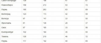
The cost of construction of power lines (power lines) is determined in accordance with the resolution of the Regional Energy Commission of Moscow dated December 27, 2012 No. 421, as compensation for costs for OJSC MOESK for the construction of 1 km of power lines.
Don't think that power lines
placed as conveniently or as desired.
There are very strict requirements for compliance with standards. The construction
and installation of power lines is carried out exclusively on the basis of a variety of state standards and documents that oblige compliance with all safety rules when performing electrical installation work. Specialists must be highly qualified and have comprehensive knowledge in the field of electrical engineering.
It must be remembered that there are clear standards, such as span length, distance of wires to the ground, that must be observed. For example, the intermediate span between supports varies between 30-50 m, depending on the type of supports, the climate of the area, and other conditions. The sag of the boom depends on the same conditions as the span.
Substation planning
First of all, the contractor studies the client's needs. The technical specifications contain information about:
- load;
- cost;
- PS parameters;
- site requirements;
- construction timing;
- selection of component equipment.
An important design condition is taking into account the current and predicted parameters of the electrical network and consumer loads. This is important, since the electrical installation is not installed separately, but together with the general supply system.
Network configurations are dictated by the PS parameters:
- the ability to supply power to consumers when heating systems are turned off in the summer;
- density of total and specific load (taking into account the reload and station load factors);
- the need for power backup during times of emergency when the generator connected to the main switchgear fails;
- own needs of the PS.
After collecting information, engineers formulate requirements for the electrical substation and prepare feasibility studies. The result of the design is the creation of a project for the construction of a substation that combines manufacturability, efficiency, reliability and modern equipment.
Site selection
The site for the substation is chosen to be of considerable size, since for insulation of conductive parts and safety it is necessary to maintain a large distance between the structural elements. There should be no obstacles on the site:
- anthropogenic;
- natural.
To ensure safety during construction, wetlands are excluded. The site should be as far away from residential areas as possible so as not to cause harm to human health and the environment.
Determine a suitable site, focusing on the acts:
- on environmental protection;
- land and water legislation;
- on environmental management.
When choosing a site, study:
- network development scheme for a district or enterprise;
- maps of urban and regional planning;
- guidelines for choosing a site for a substation up to 35 kW and more.
Experts also use methods of technical and economic comparisons of all options.
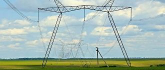
When choosing a site, they are guided by sound principles of land use, taking into account the planned development of the site in the future. When placing a substation, it is possible to install an overhead power line along corridors of the required width.
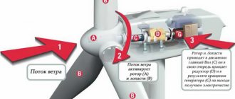
Installation of overhead lines
In most cases, with difficult terrain, it is advisable to install overhead lines
"under tension" The modern method can significantly reduce labor costs, as well as the costs of special equipment.
When performing installation “under tension”, there is no need to first roll out the wire or cable on the ground. The tensioned wire is not damaged by chips or scratches. The possibility of corona discharge is excluded.
The use of programmable tensioning machines simplifies the installation of line crossings across transport, railway tracks, and engineering structures. Rolling is carried out with special rollers directly onto the supports.
Damage to the tensioned wire is almost impossible. Special hydraulic machines turn off when the desired level of tension is reached.
Subtleties of vertical planning of substation construction
Using the vertical layout of the territory, use:
- a continuous planning system, performing work throughout the site;
- local (selective) system, carrying out work on the site with the buildings located, preserving the natural topography of the remaining territory.
The selective system is used in areas with rocky soil where trees need to be preserved. When vertical planning is used, natural relief with zero balance of earth masses is most often used.
The table shows the permissible surface slopes along the cells of open switchgear:
| Priming | Maximum permissible slope |
| Clayey | 0,05 |
| Sandy | 0,03 |
| Permafrost | 0,03 |
| Easily erosable | 0,01 |
| Landing (second type) | 0,005 |
In mountainous and rugged terrain, the site is planned with terraces. Their conjugation is carried out by slopes. If the conditions are cramped, then they are replaced with retaining walls no more than 2.5 meters high.
Substation in a mountainous area
Source: https://www.fsk-ees.ru
The work project defines the following technological sequence for the construction of power lines, which must be strictly observed along the route:1. Preparatory work - laying out the centers of supports and the axis of power lines (industrial picketing), cutting down glades and clearing the route, demolition of buildings, reconstruction of engineering structures, construction of temporary roads, buildings and structures, removal of materials to on-site warehouses.
The breakdown of the power line route from benchmarks and corner signs of the pipeline is usually carried out by customers or, if necessary, by a design organization. The broken route in kind with the necessary materials (acts, diagrams, etc.) is transferred to the construction and installation organization no less than ten days before the start of construction and installation work. The layout of support centers in situ can be carried out by a construction and installation organization, but at the expense of the customer.
The cutting down of glades and clearing of the route, the demolition of buildings, the reconstruction of engineering structures, the construction of temporary structures and roads is carried out by the general contractor. Moreover, clearings must be cut and cleared simultaneously with the preparation of the pipeline route, regardless of the timing of the start of construction of the power line.
2. Delivery of supports along the route to the pickets, metal structures, removal of wires, insulators, coupling fittings and other materials.
3. Assembly of supports, i.e. equipping them with traverses, hooks or pins, insulators, as well as grounding.
The sequence of these two operations can be mutually changed. If the power transmission line route is located near the MZU of the construction and installation department or if the racks of the supports are addressed directly to the station or pier of the destination of the construction and installation organization, then the supports can be collected at the SMU landfill and transported to the route. Sometimes it is preferable to organize a site for the assembly of supports at the destination station when they arrive en masse at this station.
4. Installation of supports with excavation work (drilling pits), their fastening and installation of grounding. If the supports are installed in drilled pits, then the drilling of the pits is carried out by a subcontractor construction and installation organization conducting the construction of power transmission lines. When installing supports in rocky soils and swamps, the excavation work must be carried out by a general contractor, i.e. the organization leading the construction of the pipeline itself. In the first case, he is obliged to carry out drilling and blasting operations in rocky soils to install supports and bring in soil to fill the pits of the pits, and in the second, to drive piles in swampy and peaty soils under the supports.
5. Rolling out wires and lifting them onto supports, connecting wires.
6. Tensioning, sighting and securing wires to supports.
Changing the accepted rational sequence of individual operations, as a rule, leads to an increase in labor costs, an increase in construction time, and a decrease in the quality of construction and installation work.
The construction of along-route power lines for a voltage of 6-10 kV, subject to the specified sequence of work, is carried out using an integrated or continuous method.
During construction using the integrated method, all technological operations for the construction of a power line section are performed by one integrated team. At the same time, the team is equipped with the necessary machines and mechanisms with which it performs all types of work on the construction of the line. This construction method justifies itself on short lines (10-15 km) and under normal geological and soil conditions of the power line route. Moreover, part of the work on the construction of power lines (cutting glades, clearing routes), as discussed earlier, is carried out by the general contractor simultaneously with the construction of the pipeline.
When constructing long lines in difficult geological and soil conditions, the continuous construction method is considered more rational and efficient. When organizing the construction of power lines using the in-line method, certain types of work are entrusted to a specialized team of workers or an enlarged unit.
First, the first team or unit begins work, for example, driving piles. Following this, the second team begins work on assembling and installing supports, having a ready-made front of work in the form of driven piles. In this case, as a rule, the supports are transported to the highway by a special transport team in such a way that the team for assembling and installing the supports constantly receives new batches of supports. With a fairly clear organization of work and when the intermediate supports are transported in assembled form, the support installation team is able to place them in driven piles without unloading at the picket, i.e. "from the wheels." Following the team for installing the supports, a team for rolling out, connecting and lifting wires to the supports comes into work, then a team or team for securing the wires, and then a team for installing mast-mounted or ground-based transformer substations, sectioning points, SK3 piping, linear valves and other electrical consumers . If the line has a large number of cable transitions and inserts, a team of cable workers is organized to perform cable work.
This ensures the continuous and consistent implementation of technological operations for the construction of power lines on certain sections of the route, called sections of the work front, i.e. the technological flow is carried out. As the power line is being constructed, the work front moves along with the team or group of workers working on the line. Typically, the scope of work must be at least the length of the anchor span so that the wire installation team can completely complete the work of rolling out, lifting and tensioning the wires. Very often, the length of the work front is determined by the section of lines from one power consumer of the pipeline to another, since anchor supports are placed at these points, and the length of such power line sections does not exceed 5-7 km.
When organizing the construction of pipeline power supply facilities using an integrated or continuous method, in each case special attention must be paid to the industrialization of construction and installation work. The industrialization of work is mainly carried out by performing the largest possible share of work off the route - in factories, assembly and procurement areas, workshops, which makes it possible to speed up and simplify the installation of structures on the route and in many cases replace installation with simple assembly.
Thus, the industrial assembly of modern structures of reinforced concrete supports can be carried out at assembly and procurement sites or at special testing sites. In this case, intermediate supports can be assembled completely, and complex supports can be assembled into enlarged rack units with cross-beams and crossbars, struts with crossbars and their fastening units to the racks. In addition, it is necessary to take into account that support racks are produced by factories with grounding outlets in the butt, which often provides the required value of grounding resistance of the supports and thereby eliminates any work at the installation site of the support to ground it.
Reducing labor costs on the route, as a rule, is facilitated by a preliminary inspection of suspension and pin insulators, their installation on a support along with suspension and coupling linear fittings before lifting the support, simultaneous rolling out of three wires, etc.
All these measures must be taken into account when organizing work on power transmission line routes and be reflected in the PPR.
| Next > |
Preparatory work
After the project has been approved, immediate preparations for installation of the substation begin. For this:
- prepare a delivery schedule for parts of equipment and structures;
- a place for storing modules and transformers will be equipped on the territory;
- determine the type of transport that will transport transformers and other parts of the structure;
- check access roads and the condition of bridges;
- study the permissible dimensions of vehicles that are permitted by traffic signs along the route.
After this, they begin planning the territory at the site of the future substation. At the first stage, the foundation is poured. Most often, they choose a company that provides comprehensive services: designs, performs earthworks, delivers equipment and carries out installation.
The next stages of construction are determined by the type and size of the electrical substation. All work is carried out according to the approved plan.
Minimum distance from power lines and radiation
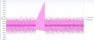
As charged particles move through wires, they create an electromagnetic field. The type of electric current determines the properties of radiation. It can be either constant or variable. Frequent changes in electric current from plus to minus and back contribute to a change in the field value several times more often.
Late at night
It has long been known that exposure to electromagnetic radiation negatively affects a person’s physical condition, just like radiation exposure. Observations on the effects of magnetic radiation on humans and the living environment began to be carried out in the early 80s.
Based on the results of a study in various countries, the WHO - World Health Organization established the maximum permissible radiation standards in hertz per unit of time.
In the Russian Federation and other countries, regulations have been approved prohibiting industrial and civil construction at a close distance from power lines.
People who were present in the zone of a powerful field for a long time subsequently noticed cancer and heart diseases. Young girls faced infertility. Men developed diseases of the genitourinary system. Chronic fatigue often manifested itself. Life expectancy in cities and villages has statistically decreased.
Classification of substations
The type of substations is determined based on the parameters and purpose according to:
- functions (step-up or step-down substation);
- nominal (maximum or minimum network voltage);
- power and number of transformers;
- finding the PS based on the entire network;
- joining method;
- the number of stages through which the reduced voltage passes.
To determine the algorithm for further actions for installing the substation, it is necessary to take into account its design, which comes in three types.
Mast transformer substation
Mast transformer substation (MTS) can be closed or open. During installation, all equipment is located on overhead power line supports. To ensure its integrity and safety (without the use of additional fencing), the optimal installation height is selected.
The open substation consists of:
- cabinets made of metal containing elements for connecting to a high voltage network (6, 10 or 35 kW);
- distribution block modules.
In a closed substation, the same components are installed in the building.
The block in which the equipment for receiving and distributing energy is concentrated is called a switchgear (switchgear). The module contains:
- several switching devices;
- protection equipment;
- automation devices;
- measuring instruments;
- connection buses;
- auxiliary equipment.
Most often, MTPs use complete distribution devices that are located outdoors. They are classified as external type. There are also closed switchgears.
The use of complete switchgears helps to minimize construction time, save labor costs, and increase safety during operation and maintenance of the substation.
Mast transformer substation
Source: https://www.brd24.com/
Closed substation
A closed substation is a separate brick building. Most often it is built on 1 or 2 floors. The foundation is usually made of blocks, but it is also possible to use strip concrete pouring. Prefabricated reinforced concrete panels are used for floors. The following is installed in the building:
- power transformers;
- low voltage panels;
- RU modules.
Closed substations are built for consumers requiring large amounts of power. For example:
- agricultural complex;
- poultry farm;
- industrial enterprise.
Sometimes a closed-type substation is installed in the building of the facility to which it is connected. For this, four rooms are prepared: each of them must have a separate entrance located from the street. The rooms are locked to limit access to unauthorized people.
To ensure safety during construction and installation of the structure, grounding is done. The procedure is carried out together with each metal case, equipment casing and the lowest voltage winding.
Closed substation
Source: https://orelgrad.ru/
Complete substation (KPS)
The electrical installation leaves the factory assembled or prepared for construction.
The table shows the advantages of CPS:
| Advantage | Description |
| Security, increased stability | The housing has a closed design, which prevents people from touching live elements of the structure. |
| Minimum installation time, savings | · prices for the construction of a complete substation are lower than other types; · installation time is reduced; · the new facility is put into operation faster. |
| Ability to quickly perform repairs | · if one of the elements fails, it will be checked and replaced in the shortest possible time; · Maintenance work will not require labor-intensive dismantling, as well as disconnecting electrical receivers. |
Most often, complete substations are installed to reduce consumer voltage:
- household;
- industrial;
- communal.
Substations of this type come in several types, which depend on:
- location;
- primary voltage;
- connection diagrams;
- number of transformers;
- climate adaptation;
- transformer parameters;
- installation method.
The substation is delivered from the factory as part of separate blocks. Each part has holes for fastening and installation. The company that is engaged in installation equips the foundation, carries out assembly work, then launches the substation and adjusts the operation of the equipment. The kit includes ventilation, communication, heating and lighting systems.
Complete substation
Source: https://tdenergo.ru/
Features of the construction of substations depending on the type
The installation of the structure directly depends on the type of substation, which can be mast-mounted, closed or complete. Each has its own characteristics.
Mast
The mast substation is the most compact of all structures. Reinforced concrete and wooden supports are used for installation. The shape of the structure is determined by the power. There are substations:
- A-shaped;
- AP-shaped;
- U-shaped.
Depending on their location in the electrical network, mast-mounted substations are either end or dead-end. To make it convenient to service them, a platform with stairs is installed. The structure is always kept locked.
Closed
Installation of a closed substation takes place in several stages:
- transportation of components to the site;
- installation of blocks on the foundation;
- bolting;
- electrical connection of modules;
- laying busbars;
- connecting cables;
- setting and checking.
Before installing a closed substation, the premises are prepared. To do this, finishing work is carried out in the rooms, the necessary holes, openings and cable channels are made, observing the conditions specified in the drawings. When placing a substation, 4 rooms are required for:
- High voltage switchgear;
- two power transformers;
- Low voltage switchgear.
A foundation is provided for all converters. Then, using loading mechanisms, the transformers are lifted and installed.
Complete
The list of works during construction includes:
- transportation;
- acceptance of equipment at the site;
- comparison by level;
- fastening works;
- welding the base with modules;
- electricity connection;
- commissioning work.
Delivery methods are determined based on the dimensions of the substation and the capabilities of the site. It is necessary to ensure that the site has multiple access roads. The best transportation option is one that ensures the preservation of cargo without intermediate unloading.
Prepare the premises in the same way as when installing a closed substation. Each block is moved with the utmost care, using special equipment and lifting mechanisms. The base is made from several reinforced concrete blocks or racks.
After completing the installation of the PTS, the necessary elements are grounded. Then the equipment is launched and adjusted. Each stage is carried out in compliance with safety precautions.
Installation of overhead power lines
Installation of 10 kV overhead lines and other voltages is significantly cheaper than laying a similar cable in the ground. Therefore, as a rule, the first option is chosen. Underground cable laying is usually practiced in urban areas due to various restrictions. All these issues are resolved before the design phase begins. If necessary, we install aerial cable lines.
The choice of method for laying lines is determined based on the results of engineering surveys, taking into account the terrain, soil types, the presence of other infrastructure along the route and other circumstances. For example, installation of a 10 kV power line involves installing supports at a distance between them of no more than 60 meters. There are many such requirements when installing overhead lines, and they must be taken into account in advance.
Territory arrangement
Fence the substation territory to the extent provided for by the project for the billing period. The territory of the site intended for subsequent expansion is specified in the project and registered as not subject to development. There is no need to protect it. It is allowed to use the territory for agricultural purposes.
The area free from development is landscaped by sowing with herbs. The area of the outdoor switchgear (open switchgear) is covered with crushed stone; gravel may be used. It is allowed to plant trees and shrubs outside the outdoor switchgear.
To provide access for duty personnel to bypass the substation, simple structures and pedestrian paths are constructed on the territory of the open switchgear. If the substations are located in a forest area, then deforestation is mandatory.
Arrangement of the substation territory
Source: https://kashira.ru
Atmospheric water removal
Water is removed from the site using a surface method, having previously agreed on the system with the interested organization. The transformer is equipped with an emergency oil sump and oil drain system. Storm water inlets are used only subject to feasibility studies.
The floor mark of the first floor must be no less than 15 centimeters above the boundary of the site adjacent to the structure. If the substation is installed in flooded or wetlands, then protection against flooding is provided.
To prevent the territory from being flooded by precipitation that flows from the mountainous sides, water protection structures (mountain ditches) are installed.
Online electrical magazine
Electronic networks (EN) located in open areas outside buildings are often made into overhead lines (OHL). The horizontal distance between the centers of two adjacent supports is taken as the length of the air strip clearance on the ground.
The anchor section is the sum of the span lengths between anchor-type supports. Under the sag of the wires f, with similar heights of the half-weight points, a vertical distance is assumed between the line connecting the suspension points and the lowest point of the wire. The dimension of the H strip is taken to be the smaller vertical distance with the greatest sag of the wires to the ground level or intersecting structures.
The angle of rotation of the line route is the angle between the directions of the lines in adjacent gaps. Wire tension refers to the force directed along the axis of the wire. The mechanical stress of a wire is obtained by dividing the amount of tension by the cross-sectional area of the wire.
Intermediate supports are installed on straight sections of the air strip route. Under normal conditions, these supports should not accept forces directed along the air strip.
Corner supports are installed in places where the direction of the air strip route is configured. Under normal conditions, these supports must take the pull of the wires of adjacent spans.
Anchor supports are installed at intersections with various structures, as well as in places where the number, grades and cross-sections of wires are configured. These supports must, in normal operating modes, accept the difference in tension of the wires directed into the distance of the air line. Anchor supports must have a rigid structure.
The end supports are installed first and at the end of the air strip. Also in places of cable inserts. They are anchor type supports. Branch supports are installed in places where they branch from the air strip.
Cross supports are installed at places where the air strip intersects in different directions.
Intermediate clearance is the horizontal distance between 2 adjacent intermediate supports. On an overhead strip up to 1 kV, the span length is from 30 to 50 m, and on an overhead strip above 1 kV, the span length is from 100 to 250 m.
Construction and design of overhead lines
Overhead strips have the following structural elements: wires, supports, insulators, fittings for fastening wires to insulators and insulators to supports. Air strips can be single-chain or double-chain. One circuit means three wires of one three-phase strip or two wires of a single-phase strip. For overhead lines, duralumin, steel-aluminum and iron wires are used. Supports for overhead lines are made of wood and reinforced concrete. Wooden supports are simple to manufacture, cheap, but short-lived. Reinforced concrete supports are more expensive, but stronger.
In the manufacture of tree support parts, softwood lumber is used. The main types of intermediate supports in Fig.
Reinforced concrete intermediate supports are made single-column with horizontal arrangement of wires on pin insulators. The supports are designed for hanging wires of grades A25 – A70, AC16 – AC50, and PS25. pin height up to 175 mm. The pins are grounded by welding to the outlets of the reinforced concrete cross-beam.
For branches up to 1 kV to building inputs, you can use duralumin wires and its alloys with a cross-section of more than 16 mm2.
On overhead lines, pin insulators are used, which are delivered to the installation site in lattice boxes. The insulators are rejected visually before sending them to the track.
Installation of power lines with voltage up to 1 kV
When the air strip passes through forests and greenery, cutting down a clearing is not necessary. Vertical and horizontal distances to wires with greater sag and small deviation to trees and bushes should be more than 1 m.
The support holes are drilled using drilling machines. If it is impossible to use drilling machines, holes are dug manually.
Under single-post supports, holes are drilled exactly along the axis of the route. When drilling, the drill rod is positioned strictly in a vertical position.
The dimensions of the support depth are determined from the table depending on the height of the supports, the number of wires mounted on the support, the type of soil, and also on the method of excavation work. When manually digging holes, they are dug 30–50 cm deeper.
The traverses of the corner supports are located along the bisector of the angle of rotation of the strip. The supports are marked with their serial number and year of installation. The numbering of the supports comes from the power source.
Crossbars, fastenings and insulators are installed before the support is raised. Insulators are carefully inspected and rejected before installation. Insulators are not required to have cracks, chips, or damage to the glaze. Cleaning insulators with an iron object is not allowed. Pin insulators are screwed onto hooks or pins wrapped in tow. The pin insulator axes are positioned vertically.
Hooks and pins are treated with asphalt varnish to protect them from rust.
The fastening of wires to pin insulators is done using wire ties.
The wires are connected using connecting clamps or welding. The wires can be connected by twisting with the following soldering. The wires are fastened to the supports in a single manner. Double fastening is carried out at intersections of the air strip with the communication and signaling line, contact wires, roads and in populated areas.
The supports, assembled and transported along the route, are installed along the route using drilling and crane machines or truck cranes.
Pin insulators mounted on hooks on the trunks of tree supports without traverses. In the support, holes are drilled with a drill into which the tails of the hooks are screwed. Pins with insulators for installation on traverses are secured with a nut.
The construction of the air strip is carried out in an in-line manner. Installation of wires is divided into operations: rolling out wires, connecting wires, lifting wires onto intermediate supports, stretching wires and fastening wires to anchor and intermediate supports.
The wires are rolled out from the drums using tractors or vehicles and are carried out from one anchor support to another.
When rolling out, mark the locations of any flaws found in the wires. Before stretching, repairs are made in these places.
Installation of overhead lines up to 10 kV
The pits for supports are laid out with a theodolite, a metal measuring tape or a tape measure according to a diagram that shows the alignment axes and dimensions of the pits at the top and bottom, taking into account the foundation used and the required steepness of the slopes. The dimensions of the bottom of the pits should not exceed the dimensions of the foundation base plate by more than 150 mm on each side.
Digging pits with vertical walls without fastenings is allowed in soils of natural moisture in the absence of groundwater.
Mechanized excavation of soil in pits is done without disturbing its structure at the base of the foundation. Therefore, excavation pits are excavated with a shortage of soil of 100–200 mm thickness. Development of soil below the design level is not allowed.
The excavated soil should be thrown back more than 0.5 m from the edge of the pit to avoid the possibility of the walls of the pit collapsing.
For the production of wooden supports for 10 kV overhead lines, pine and larch are used. The wood for the production of supports is completely sanded and impregnated with an antiseptic to ensure the resistance of the support from rotting.
When passing the air strip route with tree supports, where ground fires are likely, the supports protect against fire. To do this, ditches 0.4 m deep and 0.6 m wide are dug around each support at a distance of 2 m from it; around each support, areas with a radius of 2 m are cleared of grass and shrubs. Or reinforced concrete attachments are used in these areas.
Before installation, reinforced concrete supports are carefully inspected for the presence of cavities and potholes measuring less than 10 mm in length, width and depth. With all this, there should not be more than 2 sinks and potholes per 1 m of support length. Sinks and potholes must be sealed with a cementitious substance.
The main method of installing single-column reinforced concrete supports is to install them in drill holes with an undisturbed soil structure.
The distance from the underground part of the overhead strip support to the underground sewer pipelines must be at least 2 m for an overhead strip with voltage up to 10 kV.
When the air strip approaches the main gas and oil product pipelines, the latter must be laid outside the security zone of the air strip. For 10 kV overhead lines, the security zone is 10 m. This distance is measured from gas pipelines and oil product pipelines to the projection of the last wires. In cramped conditions, it is allowed to reduce the security zone to 5 m for overhead lines up to 10 kV.
To protect against lightning overvoltages, the following are subject to grounding: reinforced concrete supports of overhead lines with voltages up to 10 kV in populated and uninhabited areas, reinforced concrete and wood supports of all types of lines of all voltages on which lightning protection devices are installed, all types of supports on which power and instrument transformers are installed , disconnectors, fuses and other equipment.
Grounding devices for overhead lines are made of vertical grounding rods made of angle steel.
Necessary documents for launching a substation
The installation of the substation is completed by drawing up reports that comply with the requirements of regulatory and technical documentation. After they are signed, a team of adjusters is sent to the site, who:
- check the equipment connection;
- carry out tests of the substation under real operating conditions.
During work, adjusters check:
- whether high-voltage and low-voltage equipment are connected correctly;
- each accounting chain;
- alarm installation;
- relay protection;
- automation.
If all indications correspond to the project, then the results of tests and measurements are entered into the protocol of the work performed.
To put the facility into operation, the developer must contact the federal executive authority. It is also allowed to submit documentation to the local government authority that issued the construction permit.
The required package of documents includes:
- design documentation;
- building permit;
- conclusions of the examination of project documents;
- title documentation for the land plot;
- acceptance certificate for installation, construction, commissioning works;
- technical documents for components and materials provided for in the supply agreement;
- urban planning plan of the site;
- application for a permit to put a substation into operation;
- measurement and test report.
The commissioning permit is a document certifying:
- complete installation in accordance with the construction permit;
- compliance of the constructed structure with the urban planning plan and design documentation corresponding to the Urban Planning Code.
After approval of the documents, it is allowed to officially put the substation into operation. The device is supplied with rated voltage, and the structure is placed at the user’s disposal.
Cost of construction of substations
The cost of installing a substation depends on:
- selected type of equipment;
- complexity of project documentation;
- volume of work performed;
- site features.
It is most profitable to order, as it will save time and simplify the interaction process. When choosing one company, the customer will be sure that the work will be carried out promptly and consistently.
When choosing a contractor, pay attention to:
- professional experience of specialists (evaluate it based on completed projects);
- length of service of the manager supervising the work;
- appropriate permissions for employees to perform tasks.
Remember that the load and operation of the substation is different in each case. Therefore, it is important to pay increased attention to the stages of preparation and drafting of projects. Thanks to modern technologies, it is possible to calculate all the nuances and install a substation within the planned time frame without changing the engineering appearance. This increases the operating time, safety and reliability of the design.
Cable (underground) power lines
Cable power lines (CPL) are lines for transporting electricity underground or in reservoirs (in trenches) and in engineering structures (shafts, canals, chambers, pipes, overpasses, galleries, wells, ceilings).
Such highways are usually shorter than overhead lines and are more often used in densely populated cities, industrial and environmental areas.
This CLE includes:
– cable lines in reliable insulation (petroleum oil, PVC, rubber, cross-linked polyethylene, propylene rubber);
– connecting, locking and end couplings;
– fastening fittings;
– protection, control and alarm systems.
Before the construction of power lines of any capacity and installation method begins, mandatory survey activities are carried out (marking of supports on the ground and production picketing, selection of cables and equipment, power calculations and preparation of technical specifications for design).
After this, certified engineers with SRO and the necessary design approvals carry out the project and prepare a set of engineering design documentation. The project is undergoing approval by the relevant energy regulatory authorities and undergoing technical expertise.