A magnetic starter is an electrical switching device designed to start, stop and protect three-phase asynchronous electric motors with a squirrel-cage rotor by directly connecting the stator windings to the network and interrupting the current in them without first introducing additional resistances into the circuit.
In accordance with the main function of magnetic starters, the main, and sometimes the only element of the starter is a three-pole electromagnetic AC contactor, with which the main parameters of the starter are associated: rated voltage and rated current of the switched circuit, switching capacity, switching and mechanical wear resistance. In accordance with GOST, starters are intended to operate in the AC application category.
Categories of application of magnetic starters:
- AC-1 – starter load is active or low inductive.
- AC-3 – direct start mode of an electric motor with a squirrel-cage rotor, turning off a rotating motor.
- AC-4 – starting an electric motor with a squirrel-cage rotor, turning off stationary or slowly rotating engines, countercurrent braking.
The switching durability of devices in these categories is tested under conditions simulating the switching on and off of an asynchronous motor, corresponding in parameters to the nominal data of the starter, in modes determined by the category of application of the starter. As an element of automatic control systems, starters are subject to high wear resistance requirements. Starters are produced in three classes of switching wear resistance (A, B and C). The highest wear resistance is for devices classified as class A, the lowest for devices classified as class B. Switching and mechanical wear resistance for devices classified in different classes is indicated in the technical data of devices of specific types.
The switching wear resistance class is selected depending on the required service life and the expected frequency of operation in the AC-3 application category.
Irreversible connection diagram for a magnetic starter
Greetings, dear readers of the site elektrik-sam.info!
In this article we will take a closer look at a non-reversible circuit for connecting a magnetic starter to control a three-phase asynchronous electric motor.
I also recorded a video for you with a detailed description of the operation of the circuit, which you can watch at the end of this article.
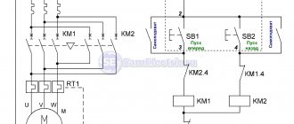
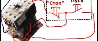
First, let's look at the connection diagram for a magnetic starter with a 220V coil.
Three phases of the supply voltage are supplied to the terminals of the asynchronous motor through:
— power contacts of the magnetic starter KM ;
- thermal relay R.
The coil winding of the magnetic starter is connected on one side to the neutral working wire N, , through a push-button post to one of the phases, in our circuit - to phase C.
The button post contains 2 buttons:
1) normally open START ;
2) normally closed - STOP .
The normally open auxiliary contact of the KM starter is connected in parallel with the START button.
To protect the electric motor from overloads, a thermal relay P , which is installed in the supply phase gap. The auxiliary normally closed contact of the thermal relay P is included in the winding circuit of the magnetic starter.
Let's consider the operation of the circuit.
We turn on the three-pole circuit breaker , its contacts close, the supply voltage is supplied to the power contacts of the starter and to the control circuit. The circuit is ready for use.
Launch.
To start the engine, press the START . The power supply circuit of the magnetic starter winding is closed, the coil armature is attracted, closing the power contacts of the CM and supplying three supply phases to the motor windings. Starting occurs and the engine begins to rotate.
At the same time, the auxiliary contact of the KM starter closes, bypassing the START .
Now, releasing the START button, power continues to flow to the starter winding through its closed auxiliary contact KM. The engine is started and continues to run.
Stop.
To stop the engine, press the STOP . The power supply circuit of the starter winding is broken. The armature, under the action of the spring, returns to its original state, opening the power contacts, thereby de-energizing the electric motor windings. He starts to stop.
At the same time, the auxiliary contact KM in the power supply circuit of the starter winding opens.
After releasing the STOP , power is not supplied to the winding, since the auxiliary contact KM is open. The engine is turned off and the chain is ready for the next start.
Overload protection.
Let's assume that the engine is running. If for some reason the motor load current increases, the bimetallic plates of the thermal relay R, under the influence of the increased current, will begin to bend and activate the release mechanism. It will open the auxiliary contact P in the magnetic starter winding circuit. The starter winding circuit will open, the power and auxiliary contacts of the starter will return to their original open state, and the engine will stop.
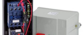
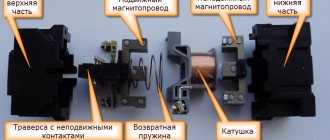
Basic device
The main advantages of this scheme are its low cost and ease of assembly, but the disadvantages of this scheme include the fact that circuit breakers are not intended for frequent switching of circuits; this, in combination with inrush currents, leads to a significant reduction in the service life of the machine; in addition, this scheme does not include Possibility of additional motor protection. The MP contactor turns on the control pulse that comes from the start button after it is pressed.
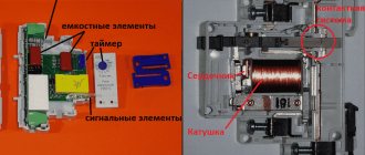
Voltage with a designation means different phases. Design of a magnetic starter In the absence of power, the springs press out the upper part of the magnetic circuit, the contacts are in their original state. You can remove the voltage from the outputs labeled T1, T2 and T3, which can be used to power a wind generator, battery and other devices. If the coil is powered by direct current, a dielectric spacer is placed on its core to prevent magnetized parts from sticking together.
The device can operate from a direct current source, and with single- and three-phase alternating current, the main thing is that its values do not exceed the rating specified by the manufacturer. This algorithm is implemented by closing auxiliary contacts in the MP. Pressing the power button closes the coil circuit. Contacts are divided into normally open - contacts that in their normal position, that is, before voltage is applied to the coil of the magnetic starter or before mechanical action on them, are in an open state and normally closed - which in their normal position are in a closed state. Since if the electromagnet is designed for constant voltage, then such a source will be needed.
Connection diagrams
So, now let’s move on to the main topic of the article – starter connection diagrams. There are two of them:
- Reversible.
- Irreversible.
How to connect a non-reversible circuit. It is standard when the electric motor connected to the network rotates in one direction.
The diagram clearly shows that the motor is started by the “Start” button located on the magnetic starter KM 1. In order not to hold this button, it is bridged with the contacts of the device. That is, when you press the “Start” button, it closes the contacts of the starter, through which current will be supplied to the electromagnetic coil of the device.
Switching off is done with the “Stop” button. On the starter diagram it is indicated by the letter “C”. This button simply opens the contacts. In this case, the core returns to its normal state under the action of the springs, and the electric motor is turned off.
In principle, the thermal relay, indicated in the starter connection diagram with the letter “P,” works in exactly the same way.
Electric motor windings
Laying windings in the stator of a single-phase electric motor
The design of any single-phase electric motor requires the use of at least three coils. Two of them are stator structural elements connected in parallel. One of them is working, and the second serves as a launcher. Their terminals are located on the motor housing and are used to connect to the network. The rotor winding is short-circuited. Two of them will be connected to the network, the rest are used for switching.
You can visually identify the working and starting windings by the cross-section of the wire: for the first of them it is noticeably larger. You can measure the resistance with a tester by connecting it to the terminals: at the working winding its value will be less. As a rule, the resistance of the windings will be no more than several tens of ohms.
Design of a reversible magnetic motor
The distribution of these modifications is becoming more widespread every year, as they help control an asynchronous motor at a distance. This device makes it possible to both turn on and off the motor .
The reversing starter housing consists of the following parts:
- Contactor.
- Thermal micro relay.
- Casing.
- Management tools.
After the “Start” command has been received, the circuit is closed. Next, the current begins to be transmitted to the coil. At the same time, a mechanical blocking device operates, which prevents unnecessary contacts from starting. It should be noted here that the mechanical lock also closes the contacts of the key, this makes it possible not to keep it pressed constantly, but to calmly release it. Another important part is that the second key of this device, together with the start of the entire device, will open the electrical circuit. Thanks to this, even pressure produces virtually no result, creating additional safety.
Features of the model's functioning
Pressing the Forward key activates the coil and makes contacts. At the same time, the operation of the start key is performed by constantly open contacts of the KM 1.3 device, due to which, when the key is directly released, the power to the coil acts bypass.
After introducing the first starter, it is the KM 1.2 contacts that open, which turns off the K2 coil. As a result, when you directly press the “Back” key, nothing happens. In order to turn the motor in the opposite direction, you need to press “Stop” and turn off the power to K1. All blocking contacts can return to the opposite state, after which it is possible to drive the motor in the opposite direction. In the same way, K2 is introduced and the block with contacts is turned off . Coil 2 of starter K1 is turned on. K2 contains power contacts KM2, and K1 - KM1. A five-core wire should be connected to the buttons for connection from the starter.
Connection rules
In any installation that requires starting an electric motor in the forward and opposite directions, there is certainly an electromagnetic device with a reversible circuit. Connecting such an element is not considered as difficult a task as it might seem at first glance. In addition, the need for such tasks arises quite often. For example, in drilling machines, cutting structures or elevators, if this does not apply to home use.
Principle of operation
The alternating current flowing through the main winding creates a periodically changing magnetic field. It consists of two circles of the same amplitude, the rotation of which occurs towards each other.
In accordance with the law of electromagnetic induction, the magnetic flux changing in the closed turns of the rotor forms an induced current, which interacts with the field that generates it. If the rotor is in a stationary position, the moments of forces acting on it are the same, as a result it remains stationary.
When the rotor rotates, the equality of the moments of force will be violated, since the sliding of its turns in relation to the rotating magnetic fields will become different. Thus, the Ampere force acting on the rotor turns from the direct magnetic field will be significantly greater than from the reverse field.
In the rotor turns, an induced current can only arise as a result of their crossing the magnetic field lines. Their rotation should be carried out at a speed slightly less than the field rotation frequency. Actually, this is where the name asynchronous single-phase electric motor comes from.
Due to an increase in mechanical load, the rotation speed decreases and the induction current in the rotor turns increases. It also increases the mechanical power of the motor and the alternating current it consumes.
Connecting the motor via starters
Irreversible magnetic starter
If it is not necessary to change the direction of rotation of the engine, then the control circuit uses two non-fixed spring-loaded buttons: one in the normal position is open - “Start”, the other is closed - “Stop”. As a rule, they are manufactured in a single dielectric housing, and one of them is red. Such buttons usually have two pairs of contact groups - one normally open, the other closed. Their type is determined during installation work visually or using a measuring device.
The control circuit wire is connected to the first terminal of the closed contacts of the Stop button. Two wires are connected to the second terminal of this button: one goes to any of the closest open contacts of the “Start” button, the second is connected to the control contact on the magnetic starter, which is open when the coil is turned off. This open contact is connected by a short wire to the controlled terminal of the coil.
The second wire from the “Start” button is connected directly to the terminal of the retractor coil. Thus, two wires must be connected to the controlled “pull-in” terminal – “direct” and “blocking”.
At the same time, the control contact closes and, thanks to the closed “Stop” button, the control action on the retractor coil is fixed. When the Start button is released, the magnetic starter remains closed. Opening the contacts of the “Stop” button causes the electromagnetic coil to be disconnected from the phase or neutral and the electric motor is turned off.
Reversing magnetic starter
To reverse the motor, two magnetic starters and three control buttons are required. Magnetic starters are installed next to each other. For greater clarity, let’s conditionally mark their supply terminals as 1–3–5, and those to which the motor is connected as 2–4–6.
For a reversible control circuit, the starters are connected as follows: terminals 1, 3 and 5 with the corresponding numbers of the adjacent starter. And the “output” contacts are crosswise: 2 from 6, 4 from 4, 6 from 2. The wire feeding the electric motor is connected to three terminals 2, 4, 6 of any starter.
With a cross connection scheme, simultaneous operation of both starters will result in a short circuit. Therefore, the conductor of the “blocking” circuit of each starter must first pass through the closed control contact of the adjacent one, and then through the open one of its own. Then turning on the second starter will cause the first one to turn off and vice versa.
Not two, but three wires are connected to the second terminal of the closed “Stop” button: two “blocking” and one supplying the “Start” button, connected in parallel to each other. With this connection scheme, the “Stop” button turns off any of the connected starters and stops the electric motor.
Carrying out preparatory work
Before connecting the thermal relay and the magnetic section, you must remember that you are working with an electrical device. That is why, in order to protect yourself from electric shock, you need to de-energize the area and check it. For this purpose, most often, a special indicator screwdriver is used.
The next stage of preparatory work is to determine the operating voltage of the coil. Depending on the manufacturer of the device, you can see the indicators on the body or on the reel itself.
Important! The operating voltage of the coil can be 220 or 380 Volts. If you have the first indicator, you need to know that phase and zero are supplied to its contacts
In the second case, this means the presence of two opposite phases.
The stage of correctly identifying the coil is quite important when connecting a magnetic starter. Otherwise, it may burn out while the device is operating.
To connect this equipment you must use two buttons:
The first of them can be black or green. This button is characterized by permanently open contacts. The second button is red and has permanently closed contacts.
When connecting a thermal relay, it is necessary to remember that the phases are switched on and off using power contacts. The zeros that approach and depart, as well as the conductors that ground, must be connected to each other in the terminal block area. In this case, the starter must be removed. These devices are not switched.
In order to connect a coil whose operating voltage is 220 Volts, you need to take a zero from the terminal block and connect it to the circuit that is intended for the operation of the starter.
Schemes for connecting magnetic starters
One of the simplest magnetic starter connection diagrams is shown below:
The principle of operation of this circuit is quite simple: when the QF circuit breaker is closed, the power supply circuit for the magnetic starter coil is assembled. The PU fuse provides short circuit protection for the control circuit. Under normal conditions, the thermal relay contact P is closed. So, to start the asynchronous machine, we press the “Start” button, the circuit closes, current begins to flow through the coil of the magnetic starter KM, the core is retracted, thereby closing the power contacts of the KM, as well as the block contact BC. The block contact BC is needed in order to close the control circuit, since the button, after it is released, will return to its original position. To stop this electric motor, just press the “Stop” button, which will disassemble the control circuit.
In case of prolonged current overload, the thermal sensor P will be triggered, which will open contact P, and this will also lead to the machine stopping.
Connection Instructions
Connection to a 3-phase network It is possible to connect 3-phase power through an MP coil operating from V.
Search on the site
Reversible circuit for connecting an electric motor through starters In some cases, it is necessary to ensure that the motor rotates in both directions. Keeping the contactor in the on state occurs according to the principle of self-retaining - when an additional auxiliary contact bypasses and is connected in parallel with the start button, thereby supplying voltage to the coil, as a result of which there is no need to hold the start button pressed. With a cross connection scheme, simultaneous operation of both starters will result in a short circuit. The coil will activate the KM1 contacts and they will close the circuit with the motor windings. Voltage with a designation means different phases.
When the armature is completely lowered, the contacts thrown by the spring are disconnected. The power supply to the control coil after connecting the magnetic starter is supplied by alternating current, but for this device the type of current does not matter. A correctly connected starter should be locked in the on position when mechanically pressing on the moving part of the magnetic circuit. The type of voltage does not matter, the main thing is that the rating does not go beyond V. Now, if you release it, the magnetic starter continues to operate until the voltage disappears or the thermal relay P for motor protection is triggered. At the same time, the starter core attracts the armature, resulting in the closure of the moving power contacts, after which voltage is supplied to the load.
But there is only one correct one. This is the so-called push-button post. You can also make a single-line graphic drawing of the connection of a three-phase electric motor to a magnetic starter via a relay. Magnetic switch. Or how to connect a three-phase motor
DC machines
Reversing starting of a DC motor can be accomplished by changing the polarity of the connection of the armature winding or field winding. Depending on how these two windings are connected, DC motors have the following types of excitation:
- independent - the field and armature windings are powered from different sources;
- sequential;
- parallel;
- mixed.
DC motors can run out - a condition of machine operation in which the speed increases so much that it causes mechanical damage.
When using a commutator motor with parallel or independent excitation, this mode may occur when the excitation winding breaks. Therefore, the connection diagram of the reversible motor in this case is constructed in such a way that the armature winding is switched, and the field winding must be directly connected to the power source. That is, it is unacceptable to connect the excitation circuit through any contacts or fuses.
Otherwise, the control circuit differs from the reversible connection of a three-phase motor only in that two DC supply wires are switched instead of three AC phases.
Operation of control circuits when the engine rotates to the right
To set the motor to rotate in the opposite direction, it is enough to swap any two supply phases, for example, “B” and “C”. This is exactly what the KM2
.
But before you press the Right
” and set the engine to rotate in the opposite direction, you need to use the “
Stop
” button to stop the previous rotation.
In this case, the circuit will break and the control phase “A” will stop flowing to the coil of the KM1
, the return spring will return the core with contacts to its original position, the power contacts will open and disconnect the motor
M
from the three-phase supply voltage. The circuit will return to the initial state or standby mode:
Press the SB3
and phase “A” through the normally closed contact
KM1.2
is supplied to the coil of the magnetic starter
KM2
, the starter is triggered and through its contact
KM2.1
stands on its own.
With its power contacts KM2
the starter will switch phases “B” and “C” in places and the motor
M
will begin to rotate in the other direction.
In this case, contact KM2.2
, located in the power supply circuit of the
KM1
, will open and will not allow the
KM1
to turn on while the
KM2
.
This is interesting: How to choose a lamp for your apartment: this is useful to know
Design and principle of operation
Magnetic contactors or starters refer to switching devices that remotely start electric motors and other equipment.
The design and circuit of these devices is very similar to an electromagnetic relay
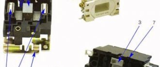
An important additional function is the ability to promptly connect and disconnect a three-phase load. The main structural element is a magnetic core made in the shape of the letter Ш
The material used was electrical steel in the form of thin sheets.
The core itself consists of two halves, one of which is stationary and is fixed to the base of the device. The other part - the movable one - in the absence of current is held at a certain distance from the fixed part by a spring. This creates an air gap between both parts.
The starter is controlled through a coil placed on the central rod of the core, located in the stationary part. Contacts are attached to the moving magnetic circuit through a bridge connection. At the moment the starter is triggered, these bridges move simultaneously with the magnetic circuit and make a short circuit with the fixed contact group.
The starting device is triggered after voltage is applied to the control coil. An electromagnetic force arises, under the influence of which the moving part of the core is attracted to the stationary part. As a result, the power contact groups become closed, and current begins to flow to the output terminals. After the voltage supply is stopped, the coil is de-energized and the moving part returns to its place. At this moment, the return spring is activated, ensuring the opening of the contacts.
During switching off, a double gap is formed at each pole of the contacts, facilitating more efficient extinguishing of the electric arc. The function of the arc chute is performed by the device cover, under which the contacts are located.
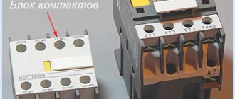
The starter has not only the main contact group, but also an additional one - in the form of block contacts, used for auxiliary purposes. They are mainly used in control, signaling and blocking circuits.