Hello, dear readers of the site. With this article we will begin the study of a magnetic starter and everything connected with it, and the idea for this topic was suggested by a regular reader of the site, Sergey Kr.
Magnetic switch
is a switching device and belongs to the family of electromagnetic contactors, which allows switching powerful loads of direct and alternating current, and is intended for frequent switching on and off of power electrical circuits.
Magnetic starters
They are mainly used for starting, stopping and reversing three-phase asynchronous electric motors, however, due to their unpretentiousness, they work perfectly in remote control circuits for lighting, in control circuits for compressors, pumps, crane beams, heating furnaces, air conditioners, belt conveyors, etc. d. In short, a magnetic starter has a wide range of applications.
As such, magnetic starters are already difficult to find in stores, since they have practically been replaced by contactors
. Moreover, in terms of its design and technical characteristics, a modern contactor is no different from a magnetic starter, and they can only be distinguished by name. Therefore, when you purchase a starter in a store, be sure to specify whether it is a magnetic starter or a contactor.
We will look at the design and operation of a magnetic starter using the example of a KMI
– small-sized AC contactor for general industrial use.
Magnetic starter device.
The magnetic starter consists of two parts: the starter
and
contact block
.
Although the contact block
and is not the main part of a magnetic starter and is not always used, but if the starter operates in a circuit where additional contacts of this starter must be used, for example, reversing an electric motor, signaling the operation of the starter or turning on additional equipment by the starter, then for multiplication of contacts, just and serves as a contact block or, as it is also called,
a contact attachment
.
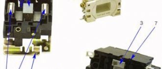
Contact block or contact attachment.
A movable contact system is built inside the contact block (contact attachment), which is rigidly connected to the contact system of the magnetic starter and becomes one with it. The attachment is attached to the top of the starter, where special skids with hooks
.
The contact system of the set-top box consists of two pairs of normally closed
and two pairs
of normally open
contacts.
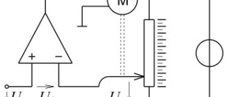
To go further, let's immediately understand: what are normally closed and normally open contacts. The figure below schematically shows the button
with a pair of contacts numbered
1-2
and
3-4
, which are fixed on a vertical axis.
The right side of the figure shows a graphical
representation of these contacts used on electrical circuit diagrams.
Normally open (NO)
The contact in the non-working state is always
open
, that is, not closed.
In the figure it is indicated by a pair 1–2
, and in order for current to pass through it, the contact must
be closed
.
Normally closed (NC)
When not in use, the contact is always
closed
and current can flow through it.
In the figure, such a contact is indicated by a pair 3–4
, and in order to stop the flow of current through it, the contact must
be opened
.
Now, if you press the button, the normally open contact 1-2 will close
, and the normally closed 3-4
will open
. This is what the picture below shows.
Let's return to the contact block. In the initial state, when the magnetic starter is de-energized
, normally open contacts
53NO–54NO
and
83NO–84NO
are open, and normally closed contacts
61NC–62NC
and
71NC–72NC
are closed. This is indicated by a nameplate with the numbers of the contact terminals located on the side wall of the contact block, and the arrow shows the direction of movement of the contact group.
Now, if supply voltage is applied to the starter coil, the core will pull the contacts of the contact block with it and the normally open ones will close
, and normally closed ones
will open
.
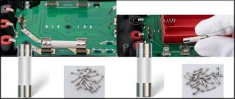
The contact block is fixed on the starter with a special latch. To remove the block, just lift the latch and push the block towards the latch.
The difference between variable and constant
First of all, DC voltage must be generated at substations with a relatively low voltage to be provided to the consumer (220V). However, when several devices are connected simultaneously, the total value increases. In this situation, to transmit voltage over long distances, it is necessary to use a thick and expensive cable. This is the only way to be able to transport current over long distances with minimal power losses.
Comparative characteristics of alternating and direct current Source electricvdome.ru
In the AC example, the generated electricity is able to travel a long distance with minimal losses. Since 1980, it has become possible to rectify three-phase electric current and convert it back.
The main difference between AC voltage and DC current is that the latter shows comparative stability. By this we mean that it does not change the frequency of the direction of movement.
Healthy! The most common frequency in the world is 50 Hz.
Due to the fact that the movement of direct current flows more uniformly, the direction of electron flow is strictly in one direction. Moreover, the source in this situation has both a positive and a negative pole. Thus, direct current is mainly used in high-voltage lines (for transportation over long distances). After converting to a variable, it is transmitted to our sockets.
Transformer that converts direct to alternating current Source livejournal.com
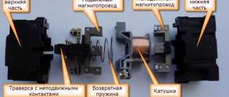
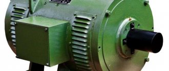
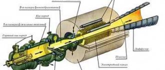
Magnetic switch.
The magnetic starter consists of an upper and lower part.
In the upper part there is a movable contact system, an arc-extinguishing chamber and a movable half of the electromagnet, which is mechanically connected to a group of power contacts of the movable contact system.
The lower part of the starter consists of a coil, a return spring and the second half of the electromagnet. The return spring returns the upper half to its original position after the power supply to the coil is stopped, thereby breaking the power contacts of the starter.
Both halves of the electromagnet are made of W-shaped plates made of electromagnetic steel. This can be clearly seen if you pull out the bottom half of the electromagnet.
The starter coil is wound with copper wire and contains the N number of turns, designed to connect a specific supply voltage of 24, 36, 110, 220 or 380 Volts.
Well, how does the process itself happen? When supply voltage is applied, a magnetic field appears in the coil and both halves tend to connect, forming a closed circuit. As soon as we turn off the power, the magnetic field disappears, and the upper part returns to its original position by a return spring.
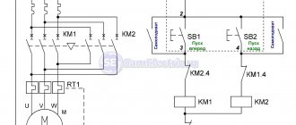
Now all that remains is to figure out the power supply and characteristics. On the side wall of the starter, just like the contact block, there is information about the electrical parameters of the starter and, for convenience, it is conventionally divided into three sectors:
Sector No. 1.
The first sector provides general information about the starter and its scope:
50 Hz
– rated frequency of alternating current at which uninterrupted operation of the starter is possible;
Application category AC-3
– motors with squirrel-cage rotor: starting, shutting down without preliminary stopping. For example: This starter can be used to start and stop squirrel cage induction motors used in elevators, escalators, conveyor belts, elevators, compressors, pumps, air conditioners, etc.
application categories are established to characterize the switching capacity of contactors and AC starters
, which are standard:
AC1
,
AC2
,
AC3
,
AC4
. Each application category is characterized by the values of currents, voltages, power factors or time constants, test conditions and other parameters established by GOST R 50030.4.1-2002.
Ie 9A
– rated operating current. This is the load current that, during normal operation, can pass through the power contacts of the starter. In our example, this current is 9 Amperes.
Application category AC-1
– non-inductive or weakly inductive loads, furnaces, resistances. For example: incandescent lamps, heating elements.
Ith 25A
– conditional thermal current (t° ≤ 40°).
This is the maximum
current that a contactor or starter can carry in 8-hour operation without the temperature rise of its various parts exceeding 40°C.
Sector No. 2.
This sector indicates the rated power
load that can be switched by the power contacts of the starter, and which is characterized by application category
AC3
and measured in
kW
(kilowatt). For example, through the contacts of the starter you can pass a load with a power of 2.2 kW, powered by an alternating voltage of no more than 230 Volts.
What is AC
The translation of the abbreviation AC from English means Alternative Current. Accordingly, DC, which is read as Direct Current, denotes a constant voltage flowing in one direction. Each is used to power electrical appliances and plays a key role in the integrity of electrical equipment if not properly connected.
Healthy! An electric current that does not change its magnitude and direction over time is called constant.
Alternating current is the form widely used by consumers to ensure the functionality of essential electrical equipment. Mostly the standard waveform in electrical circuits is presented in the form of a sinusoidal curve, with a positive half-cycle equal to the positive voltage flow and vice versa.
Sine wave of direct and alternating current Source yandex.net