Most experienced car owners have managed to acquire their own charger, which helps maintain performance and extend the life of the battery.
The best chargers (chargers) are characterized by the ability to smoothly regulate current and output voltage parameters. If you have a conventional step switch at your disposal, then it will not be possible to achieve a similar effect on the indicators.
But you can use an electrical circuit with a thyristor in the main role. This element is capable of influencing the voltage and current in the load.
Buying such a unit from the manufacturer is quite expensive. If you know how to work with a soldering iron and also understand radio engineering, then you can consider the option of assembling a thyristor-type charger with your own hands.
It will be much cheaper than buying a ready-made unit. Plus, you will be able to develop your own skills and gain new experience.
What is phase-pulse control
Here we are talking about the principle of phase-pulse regulation of power parameters, which is achieved through the use of a thyristor. This implies the use of one of the operating modes of the element.
During phase-pulse operation, the voltage indicator changes due to a change in the conductivity interval within the used mains voltage. In the domestic case, this is standard 220 V.
This regulation allows the thyristor to open and close at every 1/2 cycle. The result is 100 cycles in 1 second.
Using this method, it is possible to change voltage readings constantly and with a high level of accuracy. And under load conditions with low inertia parameters, this is extremely important.
This opens up excellent opportunities for assembling thyristor-based chargers for car batteries.
Description of design and principle of operation
The thyristor consists of three parts: “Anode”, “Cathode” and “Input”, consisting of three pn junctions that can switch between “ON” and “OFF” positions at very high speed. But at the same time, it can also be switched from the “ON” position for different durations, i.e., over several half-cycles, in order to deliver a certain amount of energy to the load. The operation of a thyristor can be better explained by assuming that it will consist of two transistors connected to each other, like a pair of complementary regenerative switches.
The simplest microcircuits demonstrate two transistors, which are combined in such a way that the collector current, after the “Start” command, flows into the NPN transistor TR 2 channels directly into the PNP transistor TR 1. At this time, the current from TR 1 flows into the channels into the bases of TR 2. These two interconnected transistors are arranged such that the base-emitter receives current from the collector-emitter of the other transistor. This requires parallel placement.
Photo – Thyristor KU221IM
Despite all safety measures, the thyristor may involuntarily move from one position to another. This occurs due to a sharp jump in current, temperature changes and other various factors. Therefore, before you buy a thyristor KU202N, T122 25, T 160, T 10 10, you need to not only check it with a tester (ring), but also familiarize yourself with the operating parameters.
Typical thyristor current-voltage characteristics
To start discussing this complex topic, look at the diagram of the current-voltage characteristics of a thyristor:
Photo - characteristics of the thyristor current-voltage characteristic
- The segment between 0 and (Vо,IL) fully corresponds to direct locking of the device;
- In the Vvo section, the thyristor is in the “ON” position;
- The segment between the zones (Vvo, IL) and (Vн,In) is the transition position in the on state of the thyristor. It is in this area that the so-called dinistor effect occurs;
- In turn, points (Vн,In) show on the graph the direct opening of the device;
- Points 0 and Vbr are the section where the thyristor is turned off;
- This is followed by the segment Vbr - it indicates the reverse breakdown mode.
Naturally, modern high-frequency radio components in a circuit can affect the current-voltage characteristics in an insignificant way (coolers, resistors, relays). Also, symmetrical photothyristors, SMD zener diodes, optothyristors, triode, optocouplers, optoelectronic and other modules may have different current-voltage characteristics.
Photo - current-voltage characteristic of a thyristor
In addition, we draw your attention to the fact that in this case, device protection is carried out at the load input.
DIY memory assembly
Now we can talk about the thyristor charger. This circuit can be used to assemble a charger suitable for servicing a car battery.
In general, nowadays there is access to a large number of different electronic circuits. There are both complex and simple ones. Complex circuit diagrams contain all the necessary adjustments, a high level of protection, and an impressive set of components. But such circuits are expensive, and making a thyristor charger out of them for your car’s battery is not particularly profitable.
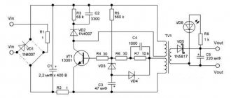
VD1 and VD2 - bridge rectifiers; VS1 - thyristor; R1, R2, R3 and R4 are resistors; C1 - capacitor; R5 - potentiometer; DA1 - microcircuit.
In most cases, when planning to assemble a battery charger using thyristors with their own hands, craftsmen use simple circuits. Such devices include several inexpensive elements. Moreover, some of them can be taken from old computers and other equipment that are no longer suitable for use.
If you are also interested in circuits for thyristor chargers to charge the battery, you need to study the entire assembly process in more detail.
We will consider almost the simplest regulator, based on a thyristor, but allowing you to charge the battery without any problems.
The process is divided into several stages:
- choosing a suitable scheme;
- selection of the necessary components;
- calculation of parameters;
- assembly.
Next, about each stage separately.
Scheme selection
The proposed circuit, according to which a homemade thyristor charger is assembled, suitable for charging a car battery, has significant advantages. This is simplicity, accessibility, reliability and minimal costs.
If you take the KU202 thyristor as a basis, then you will receive the following additional advantages:
- charging current will be up to 10A;
- pulse type energy is generated;
- assembly requires inexpensive and common parts;
- the circuit can be repeated by those who do not have extensive experience and knowledge in the field of radio engineering.
This is a really simple charger circuit for servicing a car battery. The thyristor circuit allows you to charge batteries with a nominal capacity of up to 100 Ah. After all, the charging current reaches 10A.
- The operating principle of the assembled charger is a phase-pulse type power regulator. With its help you can change the current parameters.
- The transistor circuit is powered by KU202 (control electrode).
- To protect the memory from current surges, a VD2 type diode is used.
- The resistance will affect the charge current, the value of which is 1/1 of the available battery capacity.
- To power the circuit, you need a transformer. It will reduce the mains voltage from standard 220 V to the required 18-22 V.
- If a transformer with a high output voltage is used, then the resistance should be raised to approximately 2 kOhm. It is possible that you will have to individually select the desired resistor.
- The rectifier bridge diodes, like the thyristor, are installed on aluminum radiators. This protects components from overheating.
- If you use conventional elements like D242 or D245, then you will definitely need to mark an insulating washer under the body.
A similar circuit used to assemble a thyristor charger for charging a battery is really simple. Electronic protection is not provided here. A fuse is used instead. It must be installed at the exit.
If you charge batteries with a capacity of up to 60 Ah, then it will be enough to install a fuse with parameters of 6.3 A.
It also wouldn't hurt to connect an ammeter in series. With its help, you can monitor and control the battery recharging process.
The essence of the charging manufacturing process is to make or print a board, and then connect all the components along it. The board with installed elements is enclosed in a housing, all wires are connected and tested.
Features of circuit connection
The thyristor is designed for voltage switching in various devices . But at the same time, there is a standard scheme for connecting it, which is highly recommended not to be violated. For example, a resistor must be connected between the cathode (solder pin) and the control electrode as a shunt component. Thanks to its presence, the control circuit is closed and the transition is saturated. Its resistance should be no more and no less than 51 Ohms.
If there is a voltage of negative polarity at the anode, then the control current should be zero. Otherwise, an electrical breakdown of the junction will occur, which will lead to a malfunction of the entire device. Its further operation is impossible, as is reverse restoration.
Required Components
To make a homemade thyristor battery charger, you will need to collect all the necessary elements for assembly.
In the presented embodiment, an electrolytic type capacitor is used. It can withstand a voltage of at least 63 V.
Resistors, of which 6 are required, must have a power of 0.25 W. Another resistor is needed for 2 W.
Diodes for a rectifier must pass a current of no more than 10 A, and also withstand a reverse voltage of up to 50 V. The VD2 pulse diode used will withstand a similar voltage.
The following can be used as transistors:
- KT3107;
- KT502;
- KT361;
- KT503;
- KT315;
- KT3102.
The necessary components and analogues for them include:
- rectifier unit type KTs 402, 405 with any index;
- zener diodes KS 525, KS 518 or KS 522;
- transistor KT 117 with the letters B, V and G;
- diode bridge at the output, rated for 10 A (from D242 to D247).
Of course, this is far from the only available scheme. But this is one of the simplest options for making a homemade thyristor charger.
Answers to 5 Frequently Asked Questions
Will I need to take any additional measures before charging the battery in my car? – Yes, you will need to clean the terminals, since acid deposits appear on them during operation. The contacts need to be cleaned very well so that current flows to the battery without difficulty. Sometimes motorists use grease to treat terminals; this should also be removed.
How to wipe charger terminals? — You can buy a specialized product in a store or prepare it yourself. Water and soda are used as a self-made solution. The components are mixed and stirred. This is an excellent option for treating all surfaces. When the acid comes into contact with soda, a reaction will occur and the motorist will definitely notice it. This area will need to be thoroughly wiped to get rid of all the acid.
If the terminals were previously treated with grease, it can be removed with any clean rag.
If there are covers on the battery, do they need to be opened before charging? — If there are covers on the body, they must be removed.
Why is it necessary to unscrew the battery caps? — This is necessary so that the gases formed during the charging process can freely exit the case.
Is there a need to pay attention to the electrolyte level in the battery? - This is done without fail. If the level is lower than required, then you need to add distilled water inside the battery
Determining the level is not difficult - the plates must be completely covered with liquid.
Calculation of basic parameters
The weak point of a thyristor-based charger can be considered its low efficiency. This is partly due to the presence of a secondary winding on the transformer, which must freely pass current. It is 3 times more than the power consumed by the battery. To correct this, you can move the thyristor from one winding to another according to the circuit used.
A distinctive feature of such a battery charger is that a diode bridge is connected here, as well as a regulating thyristor to the primary winding of the transformer used.
Since the secondary winding current is approximately 10 times less than the charging current, practically no thermal energy will be released on the diodes. As a result, it is not even necessary to use cooling radiators.
Product design
The UZ-A device is a rectifier with a smooth current setting. From terminals 3, 6 of network transformer T1, the voltage is supplied to a 2[-half-wave controlled rectifier made using thyristors VS1 and VS2.
The rectified voltage is supplied to the battery through contacts X1 (“plus”) and X2 (“minus”). To control the amount of charge current, use the current indicator PA1.
To disconnect the charging circuit from the battery after 10.5 ± 1 hour, control the operation of the thyristors and set the required charging current, use a circuit assembled on transistors VT1 + VT11 and a DD1 microcircuit.
On transistor VT1 there is a pulse shaper with a frequency of 50 Hz, on integrated circuit DD1 there is a pulse counter, on transistors VT8 and VT10 there is a frequency divider by 2, on transistor VT6 there is a controlled current generator (stabilizer).
In this case, the required charge current is set by potentiometer RP1.
The control pulse generator is made using transistors VTЗ and VT7.
Transistor VT2 is a power amplifier of these pulses.
Rice. 2. Schematic diagram of the automatic charging device “Electronics” - option 1 (parts are numbered according to the markings on the factory diagram).
Rice. 3. Schematic diagram of the automatic charging device “Electronics” - option 2 (parts are numbered according to the markings on the factory board).
Rice. 4. Circuit board of the automatic charging device “Electronics”.
Rice. 5. Circuit board of the automatic charging device “Electronics”.
The VT11 transistor has a protection circuit against short circuits and terminal reversal.
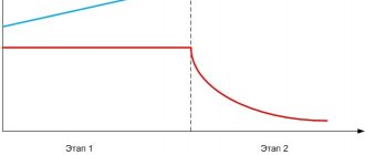
The circuit on transistors VT4 and VT5 serves to switch the device to reduced current mode (after 6 - 8 hours the current will decrease by 1.3 - 2.5 times).
The VD7 and VD8 diodes are used to assemble the power supply rectifier for the pulse shaper and counter circuit. Diodes VD5 and VD6 prohibit the supply of pulses to the control electrode of the thyristor at the moment when reverse voltage is applied to the thyristor.
LEDs VD2 and VD13 are used to indicate that the network is turned on and the end of charging.
The manufacturer reserves the right to replace individual circuit elements that do not affect the technical characteristics of the product.
Build process
Since the diagrams can be modified, plus each master sees the assembly process differently, it is difficult to describe detailed instructions here. But still, a few main points are worth highlighting. Namely:
- first, the board on which the thyristor charger will be based is printed;
- all components are installed and soldered;
- then the mounting holes are drilled;
- case components and a measuring device are selected to monitor the charging process;
- diodes and radiators are connected;
- a thyristor is installed;
- everything is well insulated;
- the front panel is made;
- wires are supplied and connected;
- final assembly of all remaining elements is performed.
All that remains is to test the resulting charger.
Yes, it may look unsightly in appearance, especially if there is no body as such. But it’s all a matter of your desire and capabilities.
Anyone who wants can go crazy and make a really beautiful case that is in no way inferior to factory chargers.
Main disadvantages
We are talking about the lack of electronic protection that could withstand a short circuit, overload, or polarity reversal. The fuse takes on part of the role of protection. But this is not the most convenient solution.
If you have the desire and experience, then you can separately assemble a protective circuit and connect it to a ready-made thyristor charger.
The second disadvantage is the galvanic connection of the tuning unit to the network. This drawback can be eliminated by using an adjusting resistance with a plastic axis.
Another disadvantage is the need to install cooling radiators. The best solution would be a finned radiator made of aluminum. The problem is partially solved. To do this, use a circuit that activates an adjustment module in the winding of the supply transformer.
In fact, assembling a thyristor charger is quite simple. But without certain skills and knowledge, taking on such work, as well as conducting experiments at home, is strongly not recommended.
How do you feel about homemade battery chargers? Has anyone assembled a charger using thyristors? Is it worth doing such homemade products?
Design
Structurally, the KU202N thyristor and the entire series are made in a metal case made of coated copper alloy, which has threaded terminals and two solder terminals of varying thickness and height. The size of the threaded outlet or anode (A) is M6 for the nut. The terminals are made rigid by filling with epoxy resin, but during installation, forces should not be used more than 0.98 N.
When soldering the power terminal (K), it is necessary to maintain a minimum distance to the glass of at least 7 mm, since high temperatures may damage its integrity. When connecting the control output (CE), you should maintain a distance to the glass of at least 3.5 mm for the same reason. In this case, the total holding time of the soldering iron is not recommended to exceed more than 3 s. The effective temperature of the soldering tool tip should not exceed +260 degrees.