What is deformation? Types of deformation
The phenomenon in which a change in the shape of a body occurs under the influence of some external force is called deformation. Its nature lies in the movement of molecules of a substance or entire layers of a crystal lattice, which leads to the appearance of so-called defects. The degree of deformation depends on many factors, among which we will consider mechanical stress.
There are several types of changes in body shape:
- Tensile deformation when an external force is applied along the entire body. Has practical value in the manufacture of ropes, cables and building materials;
- Compression strain. In this case, the vector of action of the external force coincides with the longitudinal axis of the body, but it is directed towards the center of this body. This type of deformation is used in the manufacture of metal and building materials to give them strength;
- Shear deformation occurs under the action of an external force, which is directed perpendicular to the longitudinal axis and causes the movement of different planes of the body relative to each other;
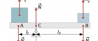
- Bending deformation is characterized by curvature of the main axis of the body, for example, when there are two points of support. The force that an object can withstand, as well as mechanical stress, play a big role in the creation of building materials;
- Torsional deformation occurs when a body rotates around its longitudinal axis. This type of deformation can be clearly demonstrated on a spring, which, after the cessation of the external force, will restore its shape.
Abstract
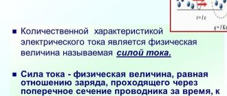
The current in a circuit is characterized by a quantity called current strength ( I ). Current strength is a physical quantity that characterizes the speed of passage of a charge through a conductor and is equal to the ratio of the charge q passed through the cross section of the conductor during a period of time t to this period of time: I = q/t . The unit of current measurement is 1 ampere (1 A).
The definition of the unit of current is based on the magnetic action of the current, in particular on the interaction of parallel conductors through which the electric current flows. Such conductors attract if the current flows through them in one direction, and repel if the direction of the current in them is opposite.
The unit of current strength is taken to be the current strength at which sections of parallel conductors 1 m long, located at a distance of 1 m from each other, interact with a force of 2 * 10-7 N. This unit is called ampere (1 A).
Knowing the formula for current strength, you can get a unit of electric charge: 1 C = 1A * 1s.
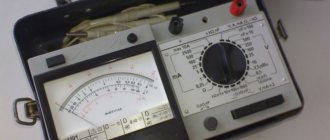
Ammeter
The device used to measure current in a circuit is called ammeter . Its work is based on the magnetic action of current. The main parts of an ammeter are magnet and coil .
When electric current passes through the coil, as a result of interaction with the magnet, it turns and rotates the arrow connected to it. The greater the current passing through the coil, the stronger it interacts with the magnet, the greater the angle of rotation of the arrow.
The ammeter is connected in a circuit in series with the device in which the current is to be measured, and therefore it has a low internal resistance, which practically does not affect the resistance of the circuit or the current in the circuit.
The ammeter terminals have “+” and “—” ; when the ammeter is connected to the circuit, the terminal with the “+” is connected to the positive pole of the current source, and the terminal with the “—” connected to the negative pole of the current source.
Voltage
The current source creates an electric field that sets electric charges in motion. A characteristic of a current source is a quantity called voltage . The larger it is, the stronger the field it creates. Voltage characterizes the work that an electric field does to move an electric charge.
Voltage ( U ) is a physical quantity equal to the ratio of the work ( A ) of the electric field to move an electric charge to the charge (q): U = A/q .
Another definition of the concept of tension is possible. If the numerator and denominator in the voltage formula are multiplied by the time of charge movement ( t ), we obtain: U = At/qt . The numerator of this fraction is the current power ( P ), and the denominator is the current strength ( I ). The formula is: U = P/I , i.e. voltage is a physical quantity equal to the ratio of the power of the electric current to the current strength in the circuit.
Unit of voltage: [ U ] = 1 J/1 C = 1 V (one volt).
Voltmeter
Voltage is measured with a voltmeter. It has the same device as an ammeter and the same principle of operation, but it is connected in parallel to the section of the circuit where the voltage is desired. The internal resistance of the voltmeter is quite large; accordingly, the current passing through it is small compared to the current in the circuit.
The voltmeter terminals have “+” and “—” ; when the voltmeter is connected to the circuit, the terminal with the “+” is connected to the positive pole of the current source, and the terminal with the “—” to the negative pole of the current source.
Formulas and definitions.
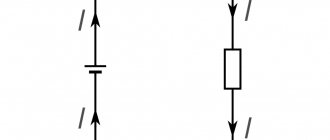
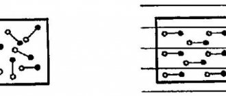
1. All conductors used in electrical circuits have symbols for depiction on diagrams and can form serial, parallel and mixed connections.
2. Current power is a physical quantity that characterizes the rate of conversion of electrical energy into its other types. The unit of measurement is 1 watt (1 W). The measuring device is a wattmeter.
3. Current strength is a physical quantity that characterizes the speed of charge passage through a conductor and is equal to the ratio of the charge passing through the cross section of the conductor to the time of movement. Unit – 1 ampere (1 A). The measuring device is an ammeter (connected in series).
4. Electric voltage is a physical quantity that characterizes the electric field that creates a current and is equal to the ratio of the current power to its strength. The unit is 1 volt (1 V). Measuring device – voltmeter (connected in parallel)
5. Current work is a physical quantity that characterizes the amount of electricity converted into other types of energy. The unit is 1 joule (1 J). The measuring device is an electric meter using a unit of 1 kilowatt-hour (1 kWh).
Lesson summary “Current strength. Voltage".
Next topic: “Electrical resistance.”
Source: https://uchitel.pro/%D1%81%D0%B8%D0%BB%D0%B0-%D1%82%D0%BE%D0%BA%D0%B0-%D0%BD%D0 %B0%D0%BF%D1%80%D1%8F%D0%B6%D0%B5%D0%BD%D0%B8%D0%B5/
Elastic and plastic deformation
Mechanical stress, which depends on the nature of the substance, affects the ability of the body to restore its original shape after a defect occurs in the crystal lattice. Based on this criterion, elastic and plastic deformation are distinguished.
With plastic deformation, the body, after exposure to an external force, is not able to restore its previous shape. For example, plasticine, when pressed with a finger, retains the resulting hole.
Elastic deformation is characteristic of those substances that are able to restore their original shape after being exposed to an external force. An example is the same spring, which, with any type of deformation described above, returns to its original state.
EMF. Ohm's law for a complete circuit
The author of the article is a professional tutor, author of textbooks for preparing for the Unified State Exam Igor Vyacheslavovich Yakovlev
Unified State Examination codifier topics: electromotive force, internal resistance of a current source, Ohm's law for a complete electrical circuit
Until now, when studying electric current, we have considered the directional movement of free charges in an external circuit
, that is, in the conductors connected to the terminals of the current source.
As we know, positive charge:
• goes into the external circuit from the positive terminal of the source;
Mechanical stress: formula and definition
The magnitude of mechanical stress is characterized by the internal forces of molecules, which are directed against the pressure and deformation of the body, per unit area.
There are two types of voltage:
- Normal stress is applied per unit area of the section parallel to the main axis of the body.
- The tangential mechanical stress is applied per unit sectional area of any other sectional plane.
To mathematically calculate mechanical stress, the formula is used: Q=F/S.
What is the meaning of total voltage?
Total stress is the part of the internal forces occurring at a specific point of the section. The designation of total voltage at a point is p. Unit of measurement – Pascal [Pa] (N/m2).
Interesting materials:
How long does it take to complete Assassin's Creed 1? How long does Mantoux take? How long does it take to pass the exam in the city traffic police? How long does it take to complete a mortgage transaction? How long does it take to complete cyberpunk? How long does it take to process an appeal? How long does it take to heat up a sauna? How long does it take for a bonsai tree to grow? How long does it take for beans to grow? How long does it take spinach to grow?
Tensile-compressive stresses.
The longitudinal force N, determined by the section method, is the resultant of the internal forces distributed over the cross section of the rod (Fig. 2, b). Based on the definition of stress, according to expression (1), we can write for the longitudinal force:
where σ is the normal stress at an arbitrary point in the cross section of the rod. To determine normal stresses at any point of a beam, it is necessary to know the law of their distribution over the cross section of the beam. Experimental studies show: if a series of mutually perpendicular lines are applied to the surface of the rod, then after applying an external tensile load the transverse lines do not bend and remain parallel to each other (Fig. 6, a). This phenomenon is evidenced by the hypothesis of plane sections (Bernoulli's hypothesis): sections that are flat before deformation remain flat after deformation.
Since all the longitudinal fibers of the rod are deformed equally, the stresses in the cross section are the same, and the stress diagram σ along the height of the cross section of the rod looks as shown in Fig. 6, b. It can be seen that the stresses are uniformly distributed over the cross section of the rod, i.e. at all points of the section σ = const. The expression for determining the voltage value has the form:
Thus, the normal stresses arising in the cross sections of a tensile or compressed beam are equal to the ratio of the longitudinal force to the area of its cross section. Normal stresses are considered to be positive in tension and negative in compression.
Tensile-compressive deformations.
Let us consider the deformations that occur during tension (compression) of the rod (Fig. 6, a). Under the influence of force F, the beam is lengthened by a certain amount Δl called absolute elongation, or absolute longitudinal deformation, which is numerically equal to the difference between the length of the beam after deformation l1 and its length before deformation l
The ratio of the absolute longitudinal deformation of a beam Δl to its original length l is called relative elongation, or relative longitudinal deformation:
In tension, the longitudinal strain is positive, and in compression, it is negative. For most structural materials, at the stage of elastic deformation, Hooke’s law (4) is satisfied, establishing a linear relationship between stresses and strains:
where the modulus of longitudinal elasticity E, also called the modulus of elasticity of the first kind, is the coefficient of proportionality between stress and strain. It characterizes the stiffness of a material under tension or compression (Table 1).
Table 1
Longitudinal modulus of elasticity for various materials
The absolute transverse deformation of a beam is equal to the difference in cross-sectional dimensions after and before deformation:
Accordingly, the relative transverse deformation is determined by the formula:
When stretched, the cross-sectional dimensions of the beam decrease, and ε' has a negative value. Experience has established that, within the limits of Hooke's law, when a beam is stretched, the transverse deformation is directly proportional to the longitudinal one. The ratio of transverse strain ε' to longitudinal strain ε is called the transverse strain ratio, or Poisson's ratio μ:
It has been experimentally established that at the elastic stage of loading of any material the value μ = const and for various materials the values of Poisson’s ratio range from 0 to 0.5 (Table 2).
table 2
Poisson's ratio.
The absolute elongation of the rod Δl is directly proportional to the longitudinal force N:
This formula can be used to calculate the absolute elongation of a section of a rod with length l, provided that within this section the value of the longitudinal force is constant. In the case when the longitudinal force N changes within a section of the rod, Δl is determined by integration within this section:
The product (EA·A) is called the cross-sectional stiffness of the rod in tension (compression).
Internal forces during tension and compression.
Axial (central) tension or compression of a straight beam is caused by external forces, the resultant vector of which coincides with the axis of the beam.
When tension or compression occurs in the cross sections of a beam, only longitudinal forces N arise. The longitudinal force N in a certain section is equal to the algebraic sum of the projection onto the axis of the rod of all external forces acting on one side of the section under consideration. According to the rule of signs of the longitudinal force N, it is generally accepted that positive longitudinal forces N arise from tensile external loads, and negative longitudinal forces N from compressive loads (Fig. 5). To identify areas of the rod or its cross-section where the longitudinal force is of greatest importance, construct a diagram of the longitudinal forces using the section method, discussed in detail in the article: Analysis of internal force factors in statistically determinable systems I also strongly recommend taking a look at the article: Calculation of a statistically determinable beam If you figure it out theory in this article and the tasks in the links, then you will become a guru in the topic “Extension-compression” =)