Question 1
Why are 4-pole and 2-pole circuit breakers needed?
Answer A
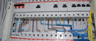
In electrical panels where the protective zero and the working zero are separated, as a rule, four-pole circuit breakers are used to protect a three-phase load, and two-pole circuit breakers are used to protect a single-phase load. The protective zero is designed in the form of a continuous bus, which is not interrupted anywhere, and the machines open one or three phases and the working zero.
Answer B
In all cases when some kind of work or maintenance is required in the line after these machines. All repair and maintenance work on electrical circuit elements must be carried out with the mains completely disconnected. Those. theoretically, it will be enough at the input of the installation (building, house), but if there is a strong branching to independent consumers (in a house these are apartments, in a factory - workshops), then it is advisable to install it on each line. But indoors, you can already install single-pole ones to control specific lines.
Answer B
Since damage and aging of insulation is possible in both phase and neutral working conductors, and the RCD responds to leakage to ground from any of them, two- and four-pole switches should be installed on outgoing lines. Only in this case is it possible to find a faulty circuit by alternately switching on the lines, including a circuit with a leak of the neutral conductor without dismantling the input distribution device, and it is also possible to disconnect the faulty circuit to ensure the operation of the rest of the electrical installation. Note: in this answer, obviously, the emphasis is on the possible installation of a machine + RCD in these circuits.
Answer B1
If at the head of a group of several circuit breakers there is an RCD, in the event of its (RCD) tripping, it is much easier to look for damage with a two-pole circuit breaker or circuit breaker (P + N). And it’s easier to wait for an electrician to be called, because... you can turn off the AV of the damaged line. In the case of single-pole circuit breakers, the entire group under the protection of the RCD is de-energized. At the same time, I note that clause 3.1.17 has nothing to do with the topic of conversation, because it refers to a fuse. It is clear that the fuse installed in N, when tripped first, will leave a phase on the damaged consumer.
The use of a two-pole AB or AB (P + N) fits well into the third paragraph of clause 3.1.18 of the “PUE”: “Releasers in the neutral conductors are allowed to be installed only on the condition that when they are triggered, all energized conductors are simultaneously disconnected from the network "
Well, if you bring it under an explosive zone: 7.3.99 “PUE”: “In explosive zones of class B-I in two-wire lines with a neutral working conductor, the phase and neutral working conductors must be protected from short-circuit currents. To simultaneously disconnect the phase and neutral working conductors, double-pole switches must be used.”
Answer D
In explosive zones of class B-I in two-wire lines with a neutral working conductor, the phase and neutral working conductors must be protected from short-circuit currents. To simultaneously disconnect the phase and neutral working conductors, two-pole switches must be used (“PUE”, 7th edition, chapter 7, clause 7.3.99).
Reference. In explosive zones of class B-I in two-wire lines with a neutral working conductor, the phase and neutral working conductors must be protected from short-circuit currents. To simultaneously disconnect the phase and neutral working conductors, two-pole switches must be used (“PUE”, 6th ed., Chapter 7.3, clause 7.3.99).
Single-terminal and double-terminal networks
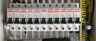
Single-pole input device
A single-pole input switch is the simplest version of a protective device that switches only one phase (see photo below).
Single pole VA
Automatic: which one to choose for an apartment
In accordance with the requirements of the PUE, the supply wire must be fixed to the upper terminal 1 of the device, and the output wire is fixed to contact 2 located at the bottom.
Important! Like any other network switch, this machine is mounted in a phase wire break (the same as a regular light switch).
This switching device has replaced the long-outdated automatic plugs, which were not so long ago installed at the entrance to old or private houses. If you find such an old input, you should immediately apply to replace it with a modern single-pole or double-pole machine, or do it yourself.
In its design and principle of operation, a modern single-pole device is practically no different from conventional linear circuit breakers, installed immediately after the electric meter and protecting individual loads. Their only difference is the different rated shutdown currents (40 versus 25 or 16 Amperes).
For schematic designation and “live” connection of a phase group, wires in red or brown insulation are used. The wire in a blue protective sheath (working zero) bypasses the machine and goes immediately to the corresponding input of the electric meter terminal block.
Two-pole device
A two-terminal network is a modular-type switching device consisting of two switching groups (figure below in the text).
Two-terminal network
The design of such a device provides for general control of both contact groups, which, when disconnected, are triggered almost simultaneously. The need for this arises for the following reasons:
- In certain situations, due to an imbalance of phase loads, some potential appears on the neutral conductor relative to the ground wire;
- Its value can reach values that are dangerous for a person who simultaneously touches zero and ground (even with a completely disconnected phase);
- Installing input devices on two poles allows you to prevent consequences possible due to installation errors (when phase and zero in the access panel are accidentally swapped).
When the phase and neutral wires are simultaneously opened, all dangerous voltages at the output of the input machine naturally disappear. And the confusion in the connection on the access panel does not matter at all for a machine disconnected from the load. Thus, when installing a two-terminal network, all expected problems are automatically eliminated.
Important! If an error is detected in the phase and zero switching, be sure to notify your local electrician.
This should be done because when installing the subsequent circuit (electricity meter, in particular), the presence of such an error may turn out to be critical. When the input machine is turned on, the meter will be connected in violation of the PUE, which threatens its owner with an inevitable fine.
Question 2
Why in Russia, unlike European countries, in TN-CS and TN-S systems it is not prescribed to use circuit breakers with the number of poles 4P (for three-phase networks) and 2P or 1P+N (for single-phase networks). Perhaps there is some political or economic background to this moment? After all, it is quite obvious that by breaking the active neutral, we increase safety and simplify the diagnostics of the electrical installation!
Answer
Viktor Shatrov, assistant at Rostechnadzor (Electrotechnics News website, https://www.news.elteh.ru/aq/?&p=3 5)
The Electrical Installation Rules do not prohibit the use of 4-pole switches in three-phase circuits and 2-pole switches in single-phase circuits to disconnect the neutral working conductor simultaneously with the phase ones. The need to install protection against short circuits in the zero working (neutral) conductor with mandatory disconnection of the neutral conductor and the effect on the simultaneous disconnection of phase conductors is provided for in clause 473.3.2.1 of GOST R 50571.9 for cases where the cross-section of the neutral conductor is less than the cross-section of the phase conductors. At the same time, conditions are specified under which detection of a short circuit current in the neutral conductor is not required. Chapter 3.1 “PUE” stipulates that releases can be installed in neutral conductors only on the condition that when they are triggered, all live conductors of the circuit are switched off. The installation of protective switching devices in the PEN conductor circuit is not allowed, except for the cases provided for in clause 1.7.145 and clause 1.7.168 of the PUE, 7th edition.
The difavtomat “DS 941” (1P+N) at overcurrent (not to be confused with leakage current) is triggered only in phase. It does not control overcurrent in the neutral.
The difavtomat “DS 652” (2P) at overcurrent is triggered in both phase and neutral. Therefore, it will tear both phase and neutral, regardless of where the overcurrent was.
What parameters are important
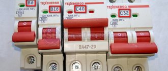
GOST classifies switches according to 12 parameters. In fact, there are even more of them, but if you choose a machine for domestic needs and “normal” operating conditions (alternating current, installation in an electrical panel, room temperature and humidity), the list can be reduced to 4-5 points. It will include: polarity, operating voltage, rated current, trip class and short circuit current.
Any amperage from 10A to 100A. Four-pole repackaged (converted) circuit breaker based on switch..
Four pole circuit breaker
On the territory of the Russian Federation, three-phase power supply systems are mainly used, and accordingly, the protection devices used in them are also three-phase. However, electrical equipment manufacturers also produce four-pole circuit breakers. Let's try to figure out in what cases the use of four-pole machines is justified, and when it is possible to get by with installing a three-pole device. Laying a cable to connect a high-power consumer is always associated with high financial costs. If the cable length is significant, sometimes it is economically justified to use a cable with a cross-section of the neutral conductor smaller than the cross-section of the phase conductors. An example would be cables VVGng 4*35+1*16 and VVGng 5*35, the difference in cost can reach 60%. By using a cable with a truncated cross-section of the neutral conductor, you can obtain noticeable economic benefits over a long laying length. In this case, according to GOST R 50571.9 “Electrical installations of buildings”, the use of a four-pole circuit breaker is prescribed for protection against short circuits.
Question 3
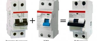
What is the difference between “1P+N” and “2P” differential circuit breakers?
Answer
The differential circuit breaker has 3 functions:
- a) overload protection;
- b) short circuit current protection;
- c) leakage protection.
- a) thermal release;
- b) electromagnetic release;
- c) RCD.
Further: “1P+N” means that the thermal and electromagnetic releases are only in the phase circuit. The zero only opens, i.e. the neutral conductor circuit does not contain the specified protections.
“2P” - accordingly, contains a bimetallic plate and an electromagnetic release coil both in the phase conductor circuit and in the neutral conductor circuit.
Question 4
Please provide a link to the document regulating the installation or absence of a switching device in the neutral working conductor for a system with a solidly grounded neutral. There is no clear indication in the PUE. Such requirements are established in foreign documentation.
Answer
Lyudmila Kazantseva, chief specialist of the Research Center “NIIProektelectromontazh” (ANO)
Clause 461.2 GOST R 50571.7-94 “Electrical installations of buildings. Part 4. Security requirements. Separation, disconnection, control" contains the instruction: "In the TN-S system, it is not necessary to separate or disconnect the working neutral conductor." “Not required” means not necessary, but possible.
In accordance with clause 1.7.8 “PUE”, the neutral working conductor is a current-carrying part. Since when the phase conductors are disconnected, as a rule, the neutral working conductor is also de-energized, the regulatory and technical documents do not require its mandatory disconnection. Typically, the need to install a switching device in the neutral working conductor is determined by operating conditions. For example, the same GOST R 50571.7-94 (clause 464.2) in places where there is a danger of electric shock requires that all current-carrying conductors, including the neutral working conductor, be disconnected with emergency shutdown devices; Clause 7.1.21 “PUE” requires that the neutral working conductor also be disconnected simultaneously with the phase conductor when supplying single-phase consumers from a multiphase supply network with branches from the overhead line. An example of a switching device that also disconnects the neutral working conductor is plug sockets. For all mobile and mobile installations, as a rule, it is necessary to disconnect the neutral working conductor simultaneously with the phase conductors of the supply cable with one common switching device.
Question 5
GOST R 50571.7-94 clause 465.1.5 states that control devices that switch power from one power source to another must act on all live conductors. At the same time, the possibility of switching on sources for parallel operation should be excluded if the installation is not specifically designed for such an operating mode. In this case, you should not disconnect the neutral working conductor combined with the protective conductor, or the protective conductor in a four-wire system. Does this mean that in the TN-S power system in the ATS box the starter must disconnect the phase and neutral working conductors?
Answer
Alexander Shalygin, Valery Shein, JSC "Roselektromontazh"
In a TN system, it is not allowed to disconnect the PEN conductor or PE conductor. As for the N-conductor, disconnecting it, as a rule, is not required. Disabling the N conductor in the TN-S system is required:
- firstly, if its cross-section is smaller than the cross-section of the phase conductors, and the protection of phase conductors from overcurrents does not simultaneously protect the N-conductor;
- secondly, if differential protection is installed at the input from the ATS. The continuity of the N-conductor in this case leads to the redistribution of zero-sequence currents from different sources and, as a consequence, uncertainty in the operation of differential protection.
Disconnection of the N conductor is also required for a number of special installations in order to increase the level of safety. For example, in accordance with the requirements of Chapter 7.1 of the PUE, in single-phase networks it is necessary to install two-pole switches. In single-phase unphased group networks (socket networks) when using phased electrical appliances of protection class I, a number of standards also require two-pole switching. When switching to a backup source (DES) when using a four-wire network, this measure is meaningless, since a jumper is installed between the PE and N buses of the input device. If it is necessary to completely separate the diesel power plant, the line from the source should be made five-wire.
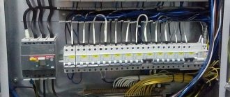
When assembling a distribution panel for a three-phase network, 3-pole circuit breakers are used. If a network overload occurs or a short circuit occurs, such a machine will disconnect three phases at once.
Input machine 4 pole
The properties of a 4-pole circuit breaker provide this device with the ability to use it to protect, first of all, 3-phase electrical networks as well as the load connected to them. In addition, a 4-pole circuit breaker is capable of reliably protecting up to 4 single-phase electrical networks in parallel mode, however, the condition is met: if a fault is detected on one of the four lines, the circuit breaker will remove power simultaneously from all four poles. Taking into account what types of releases are used in the design of this circuit breaker, it can also provide protection for connected electrical equipment from such emergencies as: Since the 4-pole circuit breaker is a modular device, it can be installed without additional modifications in a standard electrical panel on din-rail, taking up a place in it corresponding in size to four single modules (in terms of centimeters - 7.2 cm).
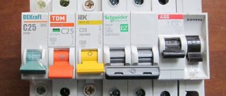
How many poles are there?
Single-pole, two-pole, three-pole and four-pole circuit breakers
In the distribution panel of an apartment or house, single-pole circuit breakers are most often used. Their task is to disconnect the phase conductor, thereby interrupting the supply of electricity to the circuit. Differential circuit breakers and RCDs disconnect both the phase and the working zero at the same time, because their operation may be due to a violation of the integrity of the wiring. The input circuit breaker in such a panel should always be two-pole.
Three-phase current is used by enterprises to power powerful units that require a voltage of 380 volts. Sometimes a four-core cable (three phases and a working zero) is supplied to a residential building or office. Due to the fact that equipment designed for such voltage is not used in these rooms, the three phases are separated in the distribution panel and a voltage of 220 is obtained between each phase and the working zero.
For such panels, 3-pole and four-pole circuit breakers are used. They are triggered when the rated load on any of the three wires is exceeded and turn them off all at the same time, and in the case of a four-pole wire, the working zero is additionally turned off.
Why use two and four poles
The input circuit breaker must completely disconnect all phases and the working zero, because One of the wires of the input cable may leak to zero and if it is not disconnected using a single-pole or 3-pole circuit breaker, there is a possibility of electric shock.
Leakage at 3-pole circuit breaker
The figure shows that in this case the entire working zero in the network is energized. If you use an input circuit breaker that disconnects phase and zero, this can be avoided; therefore, the use of four-pole and two-pole circuit breakers for three-phase and single-phase electrical networks is safer.
Features of connecting a 4-pole machine
There are no significant differences in connecting a 4-pole circuit breaker to the electrical network and the load, since this process is completely identical to the work that is carried out when connecting standard modular equipment:
The maximum number of pairs of connected wires is no more than four. That is, a 4-pole machine can operate on 2 or 3 poles, with the possibility of subsequently connecting additional wires to it to the free poles.
Taking into account the fact that the design of a 4-pole circuit breaker provides only mechanical connections and no electrical connections, it is possible to organize various methods of switching this device.
Price
3-pole circuit breakers, depending on the manufacturer, also differ in price. In the table below you can compare the cost of such electrical installation products from the most popular brands in the Russian Federation: IEK, Legrand, Schnider Electric and ABB:
Cost table for 3-pole circuit breakers leading on the Russian market
Video about switch polarity and connection methods
The video will be useful for beginners who want to understand the differences and functionality of single-pole, double-pole, 3-pole and 4-pole circuit breakers. How to connect them correctly and in what cases one or another machine should be used.
Comments:
And I thought that the three-pole one is connected as phase-zero-ground, but it turns out to be like this... Live and learn! Can it be used in a panel for a single-phase network, if three circuits need to be disconnected at once?
Evgen, why is it needed then? Power all three phases through a single-pole switch and they will turn off at the same time without any problems! And you'll save space on the rack.
Why can't you use a three-pole switch in a single-phase network? Disconnect phase, neutral and ground at the same time? If you place it, for example, at the input to the panel. It seems to me that this is more correct.
Denis, why do you need to disconnect the ground at the input? A three-pole switch is only
in a three-phase network, but using it in a single-phase network is possible, but impractical. Just as impractical as disconnecting the ground in the example you gave
Sometimes it’s useful to turn off the zero - when there is a phase imbalance, in villages all the time. But you need to tear up the ground ONLY if there is a split trans, and AFTER it.
Virtual Private Servers
One of the most prominent, in the literal sense of the word, characteristics of a circuit breaker is the characteristic that determines the number of poles of the circuit breaker.
and if you need to disconnect two phases and three-pole zero will work
Leave a comment Cancel reply
Fuel-free generator - a way to make money on illiteracy
Pros and cons of vertical wind generators, their types and features
Windmill for a private home - a toy or a real alternative
Power bank with solar battery - calculation for illiteracy
How to choose a solar panel - overview of important parameters
The purpose of circuit breakers introduced into electrical network circuits concerns protective functions. If you use a hand-held device during network overload, the likelihood of significant equipment damage increases significantly.
Automatic two-pole and three-pole switches reduce such risks to a minimum, as they provide instant circuit breakage in case of an accident.
We will understand the features of electric machines, and provide tips on choosing, installing and operating such devices.
Electric machines. Types and work. Characteristics
From the very beginning of the emergence of electricity, engineers began to think about the safety of electrical networks and devices from current overloads. As a result, many different devices have been designed that are distinguished by reliable and high-quality protection. One of the latest developments is electric automatic machines.
This device is called automatic because it is equipped with a function to turn off the power in automatic mode in the event of short circuits or overloads. Conventional fuses must be replaced with new ones after tripping, and the circuit breakers can be turned on again after eliminating the causes of the accident.
Such a protective device is necessary in any electrical network circuit. A circuit breaker will protect a building or premises from various emergency situations:
- Fires.
- Electric shocks to a person.
- Electrical wiring faults.
Types and design features
It is necessary to know information about the existing types of circuit breakers in order to correctly select the appropriate device during purchase. There is a classification of electric machines according to several parameters.
Breaking capacity
This property determines the short circuit current at which the machine will open the circuit, thereby turning off the network and devices that were connected to the network. Based on this property, machines are divided into:
- 4500 ampere circuit breakers are used to prevent faults in the power lines of older residential buildings.
- At 6000 amperes, they are used to prevent accidents during short circuits in the network of houses in new buildings.
- At 10,000 amperes, used in industry to protect electrical installations. A current of this magnitude can occur in the immediate vicinity of a substation.
The circuit breaker trips when a short circuit occurs, accompanied by the occurrence of a certain amount of current.
The machine protects electrical wiring from damage to insulation by high current.
Number of poles
This property tells us about the largest number of wires that can be connected to the machine to provide protection. In the event of an accident, the voltage at these poles is switched off.
Features of machines with one pole
Such electrical circuit breakers are the simplest in design and serve to protect individual sections of the network. Two wires can be connected to such a circuit breaker: input and output.
The purpose of such devices is to protect electrical wiring from overloads and short circuits of wires. The neutral wire is connected to the neutral bus, bypassing the machine. Grounding is connected separately.
Electrical machines with one pole are not input, since when it is disconnected, the phase is broken, and the neutral wire still remains connected to the power supply. This does not provide 100% protection.
Properties of machines with two poles
In cases where an emergency requires complete disconnection from the electrical network, circuit breakers with two poles are used. They are used as introductory ones. In emergency situations or in the event of a short circuit, all electrical wiring is switched off at the same time. This makes it possible to carry out repair and maintenance work, as well as work on connecting equipment, since complete safety is guaranteed.
Design of circuit breakers
In the practice of using such equipment, there is a frequent use of three types of devices: single-pole, two-pole, three-pole.
What is the difference between these three types of slot machines? Let's try to figure it out.
A single-pole device, in general, does not raise any special questions. If you implement a single-phase circuit breaker, the device will work like a regular switch, only in automatic response mode - that is, without user intervention, it will break the circuit in case of violation of the specified operating conditions.
Brief characteristics of a two-terminal network
A similar device, but designed in the form of a two-pole circuit breaker, is slightly different in functionality.
The circuitry of the two-pole device is made taking into account the control and comparison of the operating conditions of two independent current lines.
Two-pole circuit breakers are used, as a rule, for implementation in electrical network construction projects, when it is necessary to control and compare the operating conditions of two sections of a single electrical network. Essentially, the two-pole device configuration is a tandem of a pair of single-pole devices.
However, the two-terminal circuit protection and blocking circuit works on the principle of comparing the parameters of each device separately, in real time. If in any of the two control sections the parameters go beyond the settings, both lines are immediately broken.
This important point shows: replacing a two-pole machine with a pair of conventional single-pole devices is impossible in principle. In case of overload of one of the circuits (or short circuit), only one circuit breaker will operate.
But given that the electrical network is unified, electricity will continue to flow through the second device powering another section. Such a situation leads to dire consequences.
Meanwhile, there are two subtypes of two-pole devices:
- with single pole protection and normal neutral switching;
- with protection of both poles and their simultaneous switching.
The former are usually used as input machines, thanks to which phase and neutral conductors are switched. Moreover, this connection scheme involves the use of an additional PE line - a grounding wire.
The latter are used in circuits of one network, where two sections operating under conditions of different current loads are powered.
Features of the three-terminal device
The main purpose of a three-pole circuit breaker is to use three-phase networks in circuits. The design features of this type of device include the presence of protective functions on each individual pole.
Triggering of the protection on any of the poles leads to the opening of all poles.
Despite the specific purpose of machines of this type, it is quite acceptable to use them on single-phase or two-phase lines.
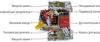
Structurally, a three-pole circuit breaker contains the following elements:
- control mechanism;
- contact system;
- arc extinguishing module;
- release device.
Free contacts are usually mounted inside the device cover. The contact system is connected to the traverse of the main contacts kinematically.
The functional components of the device are mounted inside the housing. The cover and body of the machine are made of materials that do not allow electric current to pass through (plastic, textolite, etc.).
Pole switches – reliable protection of the electrical network
A breaker pole is the part of a circuit breaker (BA) that connects to a single isolated current-carrying path. Thus, the pole of the circuit breaker is connected to its internal components: electromagnetic and thermal releases, which are connected in series and are included in the design of the circuit breaker along with the terminals and contact pair.
Features and benefits of pole switches
The VA electromagnetic release protects electrical wiring from short-circuit currents, and the thermal release provides protection against excess load current.
Pole switches are divided by the number of poles - there are models with 1, 2, 3 and 4 poles. The design of circuit breakers with a large number of poles is parallel-connected single-pole circuit breakers.
The number of poles determines how many pairs of supply wires can be connected to the machine: one wire is supplied to the input of the switch, and the second is connected to the output terminal.
The advantages of a circuit breaker over traffic jams are a high degree of safety - the releases reliably protect the wiring from short circuits and load interruptions, which ensures durability and the absence of failures in the power supply system of an apartment, cottage or house.
Automatic switch 1-pole - functionality and efficiency
If you are looking for a lower price, a single pole circuit breaker is a better option. This switch has two terminals to which the power wires are connected. The maximum distance between the terminals from each other ensures easy installation and connection, and the releases reliably protect the network from overloads. A single-pole switch, the price of which is more than affordable, is most often used in single-phase two-wire lines.
2-pole circuit breaker – increased safety
A two-pole circuit breaker has four terminals for connecting wires, located on different sides of the circuit breaker. This type of switches is used for devices with increased electrical safety requirements. One pole of the switch protects the phase wire, and the other pole protects the neutral wire. In case de-energization is necessary (possibility of an accident), the switch can protect two phase wires.
Automatic switch 3-pole and 4-pole
A three-pole switch has three pairs of terminals and is used to protect three-phase electrical circuits. It is also possible to connect a three-phase switch in such a way that one pole turns off the other two, which are connected to electrical appliances. In the event of an accident at the first pole, electrical appliances stop working.
2-pole circuit breaker – increased safety
A two-pole circuit breaker has four terminals for connecting wires, located on different sides of the circuit breaker. This type of switches is used for devices with increased electrical safety requirements. One pole of the switch protects the phase wire, and the other pole protects the neutral wire. In case de-energization is necessary (possibility of an accident), the switch can protect two phase wires.
The four-pole switch has the largest number of terminals - 8 and is used to protect three-phase wiring. This type of switch can be used as one, two or three-pole, and also implement a variety of connection schemes.
Installation details of switches
For all electrical devices of this design, the order of implementation into the electrical circuit is determined.
The established procedure, in particular, requires the following actions by installers before two-pole and three-pole switches are installed:
- the device must correspond to the design for the current circuit;
- the machine body is free from deformation and damage;
- The on/off lever works clearly in manual activation mode.
The base on which the device is supposed to be installed must be checked for evenness of the surface. Installation on bases where, due to the uneven surface after mounting, the machine body is subject to bending stresses is not allowed.
Connection to network conductors
The connection of copper conductors with a cross-section of 16 - 25 mm 2 is carried out through cable lugs ( GOST 9688-82) . If it is necessary to make a connection with copper conductors with a cross-section of 4 - 16 mm 2, cable lugs of a different type are used ( GOST 7386-80 ).
In relation to connections of aluminum wires, end elements similar to TAM-7 are used, corresponding to the parameters of GOST 9581-80 .
The network conductors supplying voltage from the power source are connected to the upper group of fixed contacts of the circuit breakers. It is necessary to supply and connect conductors so that they do not create forces on the terminals of the machine.
The tips should be tightened tightly with contact clamps, but without extreme force that could lead to thread failure. The termination of conductors in cable lugs should be given great care. Be sure to use insulating tubes and tape as a protective sheath.
Nuances of placement and fastening
When installing several pieces of equipment, it is necessary to follow the rules for arranging the devices relative to each other. Thus, the distance between closely located devices should be maintained at least 5 mm.
Minimum distances from metal parts of switchgears: from above 30 - 50 mm, from the side 5 - 10 mm, depending on the magnitude of the supplied voltage.
If the installation uses devices that are structurally made in an additional shell, all installation manipulations with them are carried out with the shell cover removed. The installation of the cover is carried out taking into account the correct insertion of the drive mechanism. The cover is fastened with screws evenly.
Upon completion of installation, the machines must be checked for clarity of the moment of switching on/off.
Wiring diagrams and rules for connecting the switch are described in detail in this article.
DC circuit breakers: what are they and where are they used?
Many people know from a school physics course that current can be alternating and constant. If we can still say something with confidence about the use of alternating current (all household electrical receivers are powered by alternating current), then we know practically nothing about direct current. But since there are DC networks, that means there are consumers, and accordingly, such networks also need protection. We will look at where DC consumers are found and what is the difference between protection devices for this type of current in this article.
Neither type of electrical current is “better” than another - each is suitable for solving specific problems: alternating current is ideal for generating, transmitting and distributing electricity over long distances, while direct current finds its application in special industrial facilities, installations solar energy, data centers, electrical substations, etc.
DC distribution cabinet for electrical substation
Understanding the differences between AC and DC provides a clear understanding of the challenges faced by DC circuit breakers. Alternating current of industrial frequency (50 Hz) changes its direction in the electrical circuit 50 times per second and “passes” through the zero value the same number of times. This “transition” of the current value through zero contributes to the rapid extinguishing of the electric arc. In DC circuits, the voltage value is constant - as well as the direction of the current is constant over time. This fact makes it much more difficult to extinguish a DC arc, and therefore requires special design solutions.
Combined graphs of normal and transient modes when disconnecting: a) alternating current; b) direct current.
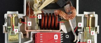
One such solution is the use of a permanent magnet (4). The movement of an arc in a magnetic field is one of the extinguishing methods in devices up to 1 kV and is used in modular circuit breakers. The electric arc, which is essentially a conductor, is affected by a magnetic field, and it is drawn into the arc-extinguishing chamber, where it is finally extinguished.
1 — moving contact 2 — fixed contact 3 — silver-containing contact soldering 4 — magnet 5 — arc chute 6 — bracket
Polarity must be observed
Another and, perhaps, key difference between AC and DC circuit breakers is the presence of polarity in the latter.
Wiring diagrams for single-pole and double-pole DC circuit breakers
If you protect a single-phase AC network using a two-pole circuit breaker (with two protected poles), then there is no difference in which pole you connect the phase or neutral conductor. When connecting circuit breakers to a DC network, the correct polarity must be observed. When connecting a single-pole DC switch, the supply voltage is supplied to terminal “1”, and when connecting a double-pole DC switch, the supply voltage is supplied to terminals “1” and “4”.
Why is this so important? Watch the video . The author of the video conducts several tests with a 10-amp switch:
1) Turning on the switch in the network with correct polarity - nothing happens. 2) The switch is installed in the network with reverse polarity; network parameters U=376 V, I=7.5 A. As a result: strong smoke emission followed by ignition of the switch. 3) The switch is installed with correct polarity, and the current in the circuit is 40 A, which is 4 times its rating. The thermal protection, as it should, opened the protected circuit after a few seconds. 4) The last and most stringent test was carried out with the same 4-fold excess current and reverse polarity. The result was not long in coming - instant ignition.
This video clearly demonstrates why polarity must be observed when connecting DC circuit breakers. Connecting with reverse polarity and with a circuit current not exceeding the rating of the circuit breaker will damage it. To avoid repetition of such “sad experiences”, manufacturers mark the terminals of the switches “+” and “-”, and also provide connection diagrams in the instruction manuals .
Thus, DC circuit breakers are protection devices used for alternative energy facilities, automation and control systems for industrial processes, etc. Special versions of the protective characteristics Z, L, K make it possible to protect high-tech equipment of industrial enterprises.
For their electrical installation, it is always recommended to use the services of qualified engineers and technicians to ensure that the appropriate DC circuit breakers are selected and installed correctly.
Maintenance during operation
Normal operating conditions of two-pole and three-pole circuit breakers make it possible to allocate time for technical inspection of devices no more than once during three years of operation. This fact once again confirms the high quality of execution of almost any machines.
Meanwhile, according to the instructions, a technical inspection must be performed if the circuit breaker has tripped due to a short circuit current.
For any reason, be it a device triggered in an emergency or scheduled maintenance, technical inspection of devices includes:
- diagnosing the on/off mechanism in manual mode without load;
- checking the tightening of the screws of the main and free contacts;
- reliability of fastening the device to the base;
- cleaning from dirt and foreign objects;
- simulating shutdown by mechanical impact on the sensitive element;
- performance check in operating mode.
The practice of using electrical networks marks the handling of devices from different manufacturers, including domestic and foreign.
The majority of all automatic protection devices in use are characterized by impeccable performance in terms of quality.