What voltage is measured in volts and watts
The number of V indicates the amount of voltage that occurs at the ends of the electrical conductor. It is also a unit of measurement of the potential difference between two points in an electrostatic field.
Current charges move from a conductor with a lower potential to a conductor with a higher potential. Such movement can be compared to the flow of water between the lowest and highest points of a river bed, and the difference between these points can be compared to the difference in potential of conductors.
Watt shows electrical, thermal and mechanical power. In mechanics, this value is equal to the ratio of the units of time and work - seconds and joules. When heat or energy is imparted at a rate of joule per second, a movement of energy with a force of 1 W occurs.
Definitions
1 volt is 1 J/1 C. That is, the potential difference will be equal to 1 V if it takes 1 joule of work to move a charge of 1 coulomb.
Moreover, for different quantities the definition of 1 volt may sound differently (example in the photo below). But the essence of the process will always remain the same: to get 1 V you need to spend 1 J to move 1 C.
What is measured in volts : electrical potential, electrical voltage, potential difference, electromotive force.
1 W is the power at which one joule of work is done in one second of time.
The basic formula for determining watt is:
\[ \begin{equation} 1 W = \frac{1 kg * 1 m^ 2}{1 s^ 3} \end{equation} \]
In addition to it, there are several more expression options (without using the main SI units):
\[ W = \frac{J}{s} = \frac{N*m}{s} = V * A\]
What is measured in watts : power, direct and alternating current power, heat flux, radiation flux and sound energy.
The main difference is that these units are designed to measure different physical quantities. Like meters are for distance, and seconds are for counting time.
To more clearly depict the difference between these concepts, it is enough to recall the process of paying for utilities. The payment goes for electricity in the network (for those same 220 V), but it is calculated in kilowatts. That is, consumers pay for what the devices were able to take from the power grid.
The confusion arises for two reasons:
- both units of measurement are interrelated. Both quantities can be found in the same formulas, as characteristics of one or another physical phenomenon;
- the names are consonant. It is also worth considering that on household electrical appliances, both V and W are usually indicated.
Differences between W and V
Characteristics by which power differs from voltage:
| IN | W |
| Shows the force required for the interaction of other quantities | Shows the amount of force that is generated as a result of the interaction of other forces |
| Associated only with electrical conductivity and electrostatic field | In addition to electricity, it measures heat and mechanical force |
The volt is a reference unit and has no predecessors. Watts replaced horsepower after the invention of the steam engine.
Regulations
Single-letter symbols of elements Letter codes corresponding to individual types of elements most widely used in electrical circuits are combined into groups designated by one symbol. The names and symbols of these radio components on the diagram are regulated by GOST 2. How various radio components are designated on the diagrams As previously said, there is a specific graphic symbol to designate radio components of each type. The directions of signal passage are indicated by arrows.
The functional diagram shows the blocks and connections between them. Principal.
The drawing shows a constant nominal resistance.
E- Symbol of a battery consisting of several batteries. There are functions that are performed only by moving contacts.
All of them also have a symbol and are applied to the corresponding contacts. According to the accepted classification, there are ten types of circuits, of which three are most often used in electrical engineering: Functional, it presents the node elements depicted as rectangles, as well as the communication lines connecting them.
The purchased components used or self-manufactured electrical electronic components are necessarily reflected in the circuit and installation electrical diagrams of the devices, in drawings and other technical documentation, which are carried out in accordance with the requirements of the ESKD standards. Designations on drawings and diagrams of elements of general use refer to qualification ones, establishing the type of current and voltage. how to learn to read diagrams
See also: Quickly create an estimate for electrical installation work
Examples from life
For safe operation, the voltage in the electrical outlet and the device must match. If you connect a toaster or hair dryer with a lower conductor potential, the device will burn out from overvoltage.
When the energy level in the network decreases, even a working refrigerator will produce less cold. Therefore, large household appliances are equipped with stabilizers. Thanks to these devices, the performance of the units does not decrease due to energy fluctuations.
Expert opinion
Karnaukh Ekaterina Vladimirovna
Graduated from the National University of Shipbuilding, majoring in Enterprise Economics
The more energy a device conducts, the higher its driving force. For example, the more intense the energy flow in the electrical circuit, the stronger the suction force of the vacuum cleaner.
Two-character letter designations
For more accurate decoding and designation of elements on electrical circuits, two-letter, and in some cases multi-letter designations are used. Marking is carried out not only with the symbol of the general code of the element, but also with additional letters that more fully reveal the characteristics of each element. In order to organize such symbolism, a table has also been created in accordance with GOST 2.710-81:
| The first letter character required to be reflected in the marking | Group of main types of elements and devices | Elements that make up the group (the most typical examples) | Two letter code symbols |
| A | General purpose devices | – | |
| B | Various types of analogue or multi-charge converters, indicating or measuring sensors, devices that convert non-electrical quantities into electrical ones, with the exception of generators and power supplies | Loudspeakers | B.A. |
| Magnetostrictive elements | BB | ||
| Detectors of ionizing elements | BD | ||
| Receivers - selsyns | BE | ||
| Capsules - telephones | B.F. | ||
| Sensors - selsyns | B.C. | ||
| Thermal sensors | B.K. | ||
| Photocells | B.L. | ||
| Microphones | B.M. | ||
| Pressure Sensors | B.P. | ||
| Piezoelements | BQ | ||
| Speed sensors - tachogenerators | BR | ||
| Pickups | B.S. | ||
| Speed sensors | B.V. | ||
| C | Capacitors | – | |
| D | Integrated circuits, microassemblies | Analog integrated circuits | D.A. |
| Integrated circuits, digital, logical elements | DD | ||
| Storage devices | D.S. | ||
| Delay devices | D.T. | ||
| E | Miscellaneous elements | Heating elements | E.K. |
| Lighting lamps | EL | ||
| Squibs | ET | ||
| F | Protective devices, fuses, arresters | Discrete instantaneous current protection elements | F.A. |
| Discrete elements of inertial current protection | FP | ||
| Fuses | F.U. | ||
| Discrete voltage protection elements, arresters | F.V. | ||
| G | Generators and other power sources | Batteries | G.B. |
| H | Indicator and signal elements | Sound alarm devices | H.A. |
| Symbolic indicators | HG | ||
| Light signaling devices | H.L. | ||
| K | Contactors, starters, relays | Current relays | K.A. |
| Indicator relays | KH | ||
| Electrothermal relays | KK | ||
| Contactors, magnetic starters | K.M. | ||
| Time relay | KT | ||
| Voltage relay | KV | ||
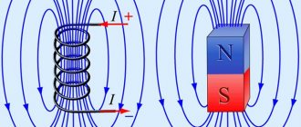
| L | Chokes, inductors | Chokes for fluorescent lamps | LL |
| M | Engines | – | |
| P | Measuring instruments and equipment (use of PE marking is prohibited) | Ammeters | PA |
| Pulse counters | PC | ||
| Frequency meters | PF | ||
| Active energy meters | P.I. | ||
| Reactive energy meters | PK | ||
| Ohmmeters | PR | ||
| Recording devices | PS | ||
| Action time meters, clocks | P.T. | ||
| Voltmeters | PV | ||
| Wattmeters | PW | ||
| Q | Switches and disconnectors in power circuits | Circuit breakers | QF |
| Short circuits | QK | ||
| Disconnectors | QS | ||
| R | Resistors | Thermistors | RK |
| Potentiometers | R.P. | ||
| Measuring shunts | R.S. | ||
| Varistors | RU | ||
| S | Switching devices in measurement, control and signaling circuits | Switches and Switches | S.A. |
| Push-button switches | S.B. | ||
| Automatic switches | SF | ||
| Switches triggered by various factors: – from the level | SL | ||
| – from pressure | SP | ||
| – from position (travel) | S.Q. | ||
| – on rotational speed | S.R. | ||
| – on temperature | S.K. | ||
| T | Transformers, autotransformers | Current transformers | T.A. |
| Electromagnetic stabilizers | T.S. | ||
| Voltage transformers | TV | ||
| U | Communication devices, converters of non-electrical quantities into electrical ones | Modulators | UB |
| Demodulators | UR | ||
| Discriminators | UI | ||
| Rectifiers, frequency generators, inverters, frequency converters | UZ | ||
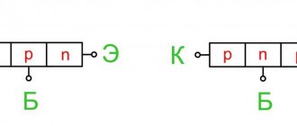
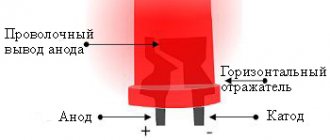
| V | Semiconductor and electrovacuum devices | Diodes, zener diodes | V.D. |
| Electrovacuum devices | VL | ||
| Transistors | VT | ||
| Thyristors | VS | ||
| W | Antennas, lines and microwave elements | Couplers | WE |
| Short circuits | W.K. | ||
| Valves | W.S. | ||
| Transformers, phase shifters | W.T. | ||
| Attenuators | W.U. | ||
| Antennas | W.A. | ||
| X | Contact connections | Sliding contacts, current collectors | XA |
| Pins | XP | ||
| Nests | XS | ||
| Separable connections | XT | ||
| High Frequency Connectors | XW | ||
| Y | Mechanical devices with electromagnetic drive | Electromagnets | YA |
| Brakes with electromagnetic drives | YB | ||
| Clutches with electromagnetic drives | YC | ||
| Electromagnetic cartridges or plates | YH | ||
| Z | Limiters, terminal devices, filters | Limiters | ZL |
| Quartz filters | ZQ |
In addition, GOST 2.710-81 defines special symbols to designate each element.
How to convert volts and watts and vice versa
To convert one indicator to another, you need to know the efficiency of the power source - efficiency.
The calculation is done using the formulas:
- W = V x efficiency;
- V = W: efficiency.
The standard efficiency range is 0.6-0.8 percent.
Resistance
Resistor
- an element of an electrical circuit that has resistance in the path of electric current.
Ohm is a unit of resistance. A resistor responds to voltage applied to it. The larger the outer surface of the resistor, the more power it can absorb.
A wire or resistor that cannot dissipate the required power becomes very hot, its resistance increases sharply and eventually it burns out. Therefore, another parameter is indicated on the resistors - power dissipation (0.125, 0.25, 0.5, 1, 2.5 or more watts).
The resistance of a conductor depends on the material, length and cross-section of the conductor. When a conductor heats up, its resistance increases. The longer the conductor, the greater its resistance, but the larger the cross-section of the conductor, the less its resistance.
Conductor connections
Series connection of two conductors
Formulas for series connection of two conductors: Itot = I1 = I2 Utot = U1 + U2 Rtot = R1 + R2
An example of calculating a circuit for serial connection of conductors
It is known that Utotal=1V, R1=R2=1Ohm, it is necessary to find U1 and U2. First you need to find Rtot, which is calculated by the formula: Rtot=R1+R2=1+1=2Ohm. According to Ohm's law, you can find Itot, which is equal to I1 and I2 and is calculated by the formula: Itot=Utot/Rtot=1/2=0, 5A Now, according to Ohm’s law, you can find U1, which is calculated by the formula: U1=R1*Itot=1*0.5=0.5B Also, according to Ohm’s law, you can find U2, which is calculated by the formula: U2=R2*Itot=1* 0.5=0.5V
Parallel connection of conductors
Formulas for parallel connection of two conductors: Itot = I1 + I2 Utot = U1 = U2 Rtot = 1/R1 + 1/R2 = (R1*R2)/(R1+R2)
An example of calculating a circuit for parallel connection of conductors
It is known Utotal=1V, R1=R2=1Ohm, it is necessary to find Itotal. First you need to find Rtot, which is calculated by the formula: Rtot=1/R1+1/R2=(R1*R2)/(R1+R2)=(1*1)/(1+1)=1/2=0, 5 Ohm According to Ohm's law, you can find Itot, which is calculated by the formula Itot=Utot/Rtot=1/0.5=2A
Emergency and abnormal operating modes of the electrical network
Short circuit - if you short-circuit two wires supplying current to an electrical device (phase and neutral), the current will sharply increase 10 times or more, and the electrical wiring may catch fire. To avoid this, the circuit breaker must turn off the mains voltage.
Overload - the current exceeds the norm for electrical wiring for a long time. To avoid this, the circuit breaker must also turn off the voltage.
Voltage deviation - the passport of an electrical device indicates the rated voltage, which ensures its normal operation. When the voltage increases or decreases, the normal operation of the electrical device is disrupted and its service life is reduced; with a significant deviation, the device may fail. In this case, a voltage stabilizer can help.
Voltage surges are short-term significant increases in voltage. Such voltage can damage household electrical appliances that contain a lot of electronics: computers, televisions, etc. It can occur when lightning strikes electrical wires or in the immediate vicinity of them, also when turning on and off powerful electrical appliances, disturbances during welding work (rarely in the city, more often in rural areas).
Voltage imbalance - some electrical appliances are under high voltage, others are under low voltage. This mode occurs as a result of a malfunction in a three-phase network, when the voltages on the phases have different values.
Phase designation (L)
The AC network includes live wires. Their correct name is “phase”. This word has English roots, and is translated as “line” or “active wire”. Phase conductors pose a particular danger to human health and property. For safe operation they are covered with reliable insulation.
The use of exposed live wires is fraught with the following consequences:
- 1. Electric shock to people. This can result in burns, injuries and even death.
- 2. The occurrence of fires.
- 3. Damage to equipment.
Grounding symbol (PE)
In addition to the designation of phase and zero, electricians also use a special letter indication PE (Protective Earthing) for the ground wire. As a rule, they are always included in the cable, along with the neutral and phase conductors. Contacts and clamps intended for switching with the grounding neutral wire are also marked in a similar way.
For ease of installation, the grounding conductors are placed in yellow-green insulation. The DIYer should understand that these colors always indicate the ground wires only. Yellow and green are never used to indicate phase and zero in electrical engineering.
As practice shows, when organizing electrical networks in residential buildings, violations of generally accepted standards for the use of insulation color and corresponding alphanumeric markings are sometimes allowed. In this case, it is not always enough to have the ability to decipher the designations L, N or PE.
In order for the connection of electrical equipment to be truly safe, it is necessary to check whether the markings correspond to the actual state of things. To do this, use special devices (testers) or improvised devices. If you have no experience in such work, for your own safety it is better to invite an experienced electrician with the appropriate permit.
Designation l and n in electrics
The designation of phase and zero in electrics was introduced to ensure that electrical networks are safe and easy to use. For this purpose, special letter markings (l and n) and insulation of the corresponding color are used. There may also be conductors marked PE in yellow-green color: this is how grounding wires are designated.
In addition, the same letter designations are used on connecting contacts and terminals. All that needs to be done when installing an electrical appliance is to connect each of the wires to the terminal. To be on the safe side, it is advisable to check each of the wires with a tester.
Zero designation (N)
To mark the neutral or zero working core of the network, use the letter “N”. This is an abbreviation of the term neutral (translated as neutral). This is what is commonly called the neutral conductor all over the world. In our country, the word “Zero” is mostly used.
Most likely, the word NULL is taken as a basis here. The letter “N” in the diagram indicates contacts or terminals intended for switching the neutral core. A similar designation is accepted for both single-phase and three-phase circuits. Blue or white-blue (white-blue) insulation is used as a color designation for the neutral wire.
Kirchhoff's laws
Kirchhoff's first law
The sum of currents entering a node is equal to the sum of currents leaving the node.
The point where several conductors converge is called a node. At any node of an electrical circuit, the algebraic sum of currents is equal to zero.
where m is the number of branches connected to the node.
Kirchhoff's second law
In any closed circuit of an electrical circuit, the algebraic sum of the EMF is equal to the algebraic sum of the voltage drops in all its sections.
where n is the number of EMF sources in the circuit; m – number of elements with resistance Rк in the circuit; Uк = RкIк – voltage or voltage drop on the kth circuit element.