The use of independent measuring instruments allows you to control the quality of power networks and load distribution. You can purchase and install a voltmeter on a DIN rail yourself. Below is an algorithm of actions that will be useful for the correct selection of products and subsequent operation.
Three-phase measuring instrument mounted on DIN rail
Features of application
DIN rail is a foreign invention that takes its name from the German standard designated DIN 43880-1988.
In our country, their use is regulated by GOST R IEC 60715-2003. These products are sometimes called mounting rail. The full name looks like this: “mounting rail for fixing protective devices in low-voltage distribution and control equipment for electrical networks.” In accordance with this definition, its scope extends to the following cases:
- the need to install electric meters and other types of measuring equipment in the distribution cabinet;
- the need to place protective equipment there (RCDs, automatic circuit breakers, voltage relays, etc.);
- If desired, install special connecting fittings into the cabinet.
Types of DIN rails
The decisive factor determining the capacity of such a rail is the width of the machine module or similar protective equipment installed on its base.
When assessing the width of the machines, they are based on the specific number of protective devices used in the panel, which can have a single-pole or multi-pole design. The second option concerns three-phase networks. In general, its use is limited to this particular set of functions, but in certain situations other directions for using the DIN rail are possible.
Dimensions and installation method
In domestic conditions, standard strips with a profile width of 35 mm (TN 35), having a shelf height of about 7.5 mm, are traditionally used.
Different versions of the product may differ in the declared thickness of the profile (1-1.5 mm) and the diameter of the holes filled during perforation (4 or 5 mm). To attach them to the distribution board guides, you will need bolts of the appropriate size. The installation product is fixed at the two extreme points of the strip in such a way that there are no parts protruding beyond the cut of the guides. That is, the length of the workpiece is selected exactly to size, for which the side excesses are cut off in advance.
Application
The measuring device is installed behind the meter and the main switch to the group of machines.
Something to remember! Devices in this category do not perform protective functions as standard. However, some models are equipped with a built-in relay that opens the circuit when the control parameter increases above an acceptable level.
In smart home systems and commercial projects, measurement results are promptly transferred to the information and control unit. To do this, they use wired communications and radio channels.
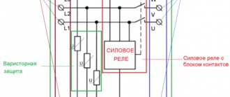
Connection diagram
The data stored in memory can be used during negotiations with electricity suppliers. After accidents, information about malfunctions will simplify the calculation of compensation for losses. If properly prepared, they will be useful for proving your case in court proceedings.
Voltammeter on DIN rail
The device measures voltage and alternating current in two ways: non-contact and contact. Connect to the circuit according to the manufacturer's instructions (indicates which terminals the wires are connected to depending on the current measurement limits).
Modern electronic devices of this type measure voltage from 20 to 450 V, are connected to phase voltage (230 V) and linear (400 V), as well as to networks with reduced voltage (24, 27, 40, 60, 80, 110 V) . The built-in current transformer allows you to measure current up to 63 A and displays the total passing power, indicated in kVA∙A. In addition, it records the min and max voltage values, as well as the number of shutdowns after the reset operation.
Features of three-phase devices
Three-phase measuring devices are represented by digital voltmeters, with the help of which technological control of the voltage value is carried out. They are designed for AC electrical circuits in industry, residential buildings and other facilities.
Voltmeters are often an integral part of systems that provide automated control over technological processes. In these cases, they are used as the main or additional means of indication. Unlike metering devices, these devices do not require periodic verification.
In addition to the power terminals, in the front part there are three-digit indicators that display the voltage value in all monitored phases. Indicators are displayed on the screens in the form of red numbers.
Three-phase voltmeters structurally contain three measuring circuits with galvanic isolation. Some models, in accordance with the connection diagram, control voltage in various types of independent lines, as well as phase and line voltages in three-phase networks.
The measuring instruments are powered from the voltage of the controlled network. Measurements are carried out over a wide range - from 50 to 450 volts. Devices operate normally at a frequency of 45-70 Hz; there are devices designed for 400 Hz.
The connection in a three-phase voltmeter is made directly to the circuit being measured. In a single-phase network, when connecting inputs, the location of the phase and neutral wires is not taken into account. In three-phase networks, the zero bus must be connected to each input of the device. Phase voltages are controlled by connecting all inputs of the measuring device between phases.
If the voltage in any line of the monitored network drops to a value below 30 volts, the numbers displaying the current voltage on the screen begin to flash every second. If during operation the voltage exceeds the maximum voltage of 450 V, the current voltage value will also flash on the indicator screen of the corresponding phase at intervals of 1 second.
Manufacturing materials and load characteristics
The material from which a particular DIN rail is made must be suitable for its purpose. This means that it is necessary to take into account the expected loads, depending on which steel or aluminum products are selected. The first of these samples are more durable in their structure and can withstand extreme loads with a minimum strip thickness of only 1 mm.
By critical or extreme loads we mean the situation when large devices such as frequency converters, powerful magnetic starters or three-phase power circuit breakers are mounted on the rail.
Load characteristics
Steel rails with a thickness of 1.0 mm can withstand maximum loads and have no restrictions on installation
. Since a typical DIN rail is produced as a profile product, it can withstand greater deformation loads than a metal plate of the same size. Typical load characteristics of DIN rails are standardized by current standards for a number of characteristics, including the type of metal. Aluminum strips are available in the following versions:
- 1 mm thick slats designed for installation of single modular devices: circuit breakers, RCD units, power modules;
- 1.1 mm strips, designed for installation of single devices placed in several rows;
- the same products, but with an indicator of 1.4 mm, designed for modular equipment of any class and weight.
All these products are cut into pieces of the required length before installation.
The kit may include steel slats with a thickness of 1.0 mm, the load capacity of which is similar to an aluminum rail with a thickness of 1.5 mm. They can withstand maximum loads without restrictions on weight and number of seats within the permissible size. In addition, manufacturers of switchboard equipment often equip distribution cabinets with non-standard profile rails.
Load characteristics of DIN rails
As you can see in the photo above, a DIN rail is a profile product and is a priori designed for high weight loads compared to a simple plate. However, there are load characteristics of DIN rails that you need to know.
- Aluminum slats 1 mm thick, designed for the installation of individual modular devices, such as circuit breakers, ouzo, power supplies. Before use, cut into short pieces.
- Aluminum slats with a thickness of 1.1 mm are designed for the installation of single modular equipment in rows.
- Aluminum slats with a thickness of 1.4 mm are designed for the installation of modular equipment of any weight.
Steel slats with a thickness of 1.0 mm, a load analogue of an aluminum slatted 1.5 mm, can withstand maximum loads and have no restrictions on installation.
I note that manufacturers of electrical panels can equip the panels with rails with other profiles. Let's look at the photo:
Design and principle of operation
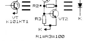
Internally, a digital ammeter consists of several main functional units. This is a comparator and voltage converter, as well as resistors, a digital processor and a data output device.
The comparator functions as an analog-to-digital converter, converting analog current data into a digital signal. These data are then displayed on the screen.
Ammeters with such a device have a number of advantages over older analog models. The latter, which use a traditional reading mechanism with an arrow, have an inconvenient feature - they do not show the current value immediately, but some time after being connected to the circuit. A digital device, on the contrary, displays information without delay. Its performance depends on the power of the computer that processes the signal.
The advantages of digital devices also include noise immunity and high accuracy. Since ammeters of this type are now popular and are installed in many types of networks, simple, convenient and universal installation schemes have been developed.
The absence of the need to calibrate the device is also an important advantage of microcontroller-based devices. After all, traditional dial indicators, like any mechanical devices, required periodic checking of the scale for accuracy, adjustment and calibration.
But their advanced capabilities come at a price—these ammeters require separate power for the electronics and display, and are more expensive than analog ones.
Connection rules
To obtain correct current measurement results, you must follow certain rules for connecting the device to the circuit and, of course, safety precautions. For example, never connect an ammeter directly to the power supply terminals. This will cause a short circuit.
The general instructions for connecting an ammeter to a circuit include setting the correct measurement limit and selecting the appropriate shunt or transformer. The shunt rating must correspond to the measurement limit that was selected, for example, using a manual selector (on portable models) or indicated in the device labeling. Otherwise, the ammeter resistors may burn out (if the current limit is exceeded).
This value can be calculated, for example, by the power of the consumer or, as is most often done, by Ohm’s law, taking as initial data the voltage at the terminals of the current source and the total resistance of the circuit.
Then you need to set the mode in which the device will operate. On portable models this is easily done using the appropriate manual selector, on programmable modules - using special jumpers. The bottom line is that the ammeter must use resistors that can withstand the appropriate limit of the current being measured. After this, you can connect the device to a shunt or transformer (if the measurement does not involve connecting an ammeter directly to the circuit).
Some models of digital ammeters may imply some kind of adjustment algorithm for connecting different types of transformers.
The next step is power supply
From this point on, you must be careful when performing measurements and do not touch any uninsulated parts of the conductors or microcircuit. After this you can read the readings from the display
The following video provides an overview of a digital ammeter and discusses how it works.
ABB products
ABB produces a wide range of measuring equipment. The most advanced automation and energy technologies are used in production.
New models include a variety of devices, including voltage indicators, that differ in their intended purpose. They provide control, protection and switching, and perform control and measurement functions. Due to their design features and dimensions, these devices are compatible with all types of existing electrical installations.
Modern modular equipment from ABB can be combined into separate groups without connecting conductors to each other, which significantly speeds up the installation process. An innovative solution is the use of bidirectional cylindrical terminals. They make it possible to simultaneously connect two conductors at the bottom and top. Each device complies with the EN 41140 standard, making them completely safe during electrical installation.
Varieties
There are several types and designs of digital ammeters that serve different purposes and have different capabilities accordingly. Ammeters vary in design - for example, panel-mounted and DIN-rail mounted. They can also be adapted to work on different networks.
DC ammeters can be used, for example, to monitor the current level in a car's on-board network and in other similar networks. Such devices are usually designed to determine the current strength in a single-phase circuit, while ammeters for industrial networks are often three-phase.
To determine and display on the screen the current value in a three-phase network, panel ammeters or more compact and convenient modular devices are usually used, which are mounted on a DIN rail (a special metal profile designed for mounting devices such as an automatic fuse or a residual current device on it). ).
Their design may provide for inclusion in the circuit via a transformer if the current in the network is sufficiently large.
Specifications
- Supply voltage: 230 V.
- Operating frequency: 50/60 Hz.
- Red LED display: 3-digit, 8 mm high.
- Full scale accuracy: 0.5% ±1 unit.
- Consumption: 5 VA max. or 2.5 VA nom.
- Protection degree: IP40 for front panel;
- IP20 at terminal level.
- safety: IEC/EN 61010-1;
Multi-range ammeter
- Rated current: direct connection: 5 A;
- when using a CT (not included in delivery) with parameter settings on the front panel of the ammeter: 10, 15, 20, 25, 40, 50, 60, 100, 150, 200, 250, 400, 500, 600, 800, 1000, 1500, 2000, 2500, 4000, 5000 A.
Download documentation
Technical description of digital ammeters AMP, voltmeters VLT and frequency meters FRE, DIN rail mounting (451.6 kB)
Types of DIN rails
Installing a circuit breaker on a DIN rail
Depending on the shape of the fastening strip, known samples of products of this class are divided into the following types:
- TN type rails (their varieties are TN 15, TN 35, TN 75);
- class “C” products (C20, 30, 40, 50);
- G-type strips (G 32).
The first of these designs is shaped like the letter of the Greek alphabet “omega” and is the most common among industrially produced samples. The housings of electricity meters and automatic machines are traditionally mounted on it.
In C-shaped models, the side edges are curved inward, so its profile allows you to fix terminal blocks of a special shape and design. The G-bar is a slightly modified modification, used extremely rarely and used for the same purposes. The length of these fasteners, depending on the manufacturer, varies from 7.5 cm to 2 meters, which allows you to place on them from 4 to 96 pieces of protective devices with the standard width of one machine module.
The advantage of the first designs is ease of installation, since if there are holes drilled in increments of 10-15 mm, it is much easier to attach a steel rail. But cast samples are more durable and reliable. They are not deformed if there are a large number of circuit breakers in the distribution panel.
Design features
This device has practically no special features as such. It is very similar to other electrical elements. And this is a plastic case, threaded or spring contacts for connecting wires and fasteners on a DIN rail, the width of which is 35 mm.
By the way, such DIN rail voltmeters can be installed and attached to a flat surface. To do this, it is necessary to move the springs of the locking fasteners to their extreme position.
Now, regarding the instrument panel. Firstly, there is a digital indicator that displays the digital value of the voltage being removed. Secondly, the indicator is illuminated in green, which allows you to clearly see the voltmeter readings at any time of the day and in any lighting. Thirdly, this is a reset button (not all models have it). Fourthly, this is a button for reading voltage readings, that is, it is used to obtain information.
The most important thing is that for the voltmeters to work there is no need to use a live connection to the network. They are directly connected to the electrical circuit in which measurements are taken. There is such a thing as a false reading. This is when the device starts to lie. But there are certain conditions for this. For example, some models give false readings at high or low voltage. To avoid this, the design of voltmeters includes a warning system. For example, in the VR-M01 or M02 voltmeters, at a low voltage of 60 volts, the letter “Lo” appears; at a voltage above 440 volts, the letter “H” appears. That is, the device signals that it cannot accurately take readings with such differences.
We must pay tribute to the manufacturers who today offer models with a pleasant number of options. Such devices can record the maximum or minimum voltage value in the supply network, their difference, as well as the time when the current supply to the house is turned off and their quantity.
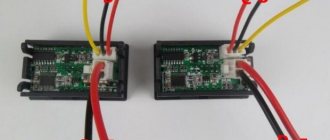
In addition to voltmeters, there are other devices of the same type on the market, with which you can measure not only the voltage in the network, but also the current consumed by household appliances and lighting. They are called voltammeters. In fact, a volt-ammeter on a DIN rail is almost exactly the same device. True, it has a slightly different connection scheme. It's also simple. By the way, in the photo below this circuit is clearly visible on the side plane of the voltammeter itself.
The variety of model range of voltmeters and voltammeters is quite huge. There are large types and designs that are used at industrial facilities and in the housing and communal services system. There are small devices that are installed in a small house or even in an apartment. The top photo shows a household-type voltammeter. It is small, compact, and easily fits into any electrical distribution panel.
Features of installation and selection
DIY digital voltmeter
Devices are created taking into account the features of installation on a DIN rail. In addition to standard fasteners, multiple sizes of 1.5 are used; 2; 2.5 relative to standard models. This simplifies the arrangement of elements. As a rule, the terminals for connecting wires are located at the bottom.
The connection is made according to the diagram specified by the manufacturer. The graphic image is provided in the accompanying instructions, in a sticker or relief picture on the case. If this data is not available, you should obtain the necessary information on the official website.
Ammeters are installed very carefully to prevent parallel connections to the network. Such an error will damage a quality product. When working with high values, use a current transformer circuit.
Select measuring instruments with comprehensive consideration:
- input parameters;
- accuracy;
- operating conditions;
- necessary service functions (memory, settings).
Manufacturer
Schneider Electric, JSC Schneider Electric is a global expert in energy management. The company's divisions successfully operate in more than 100 countries. Schneider Electric offers integrated energy-efficient solutions for energy and infrastructure, industrial plants, civil and residential buildings, and data centers. With a turnover of €22.4 billion in 2011, the company's more than 130,000 employees work hard to make energy safe, reliable and efficient. Motto. JSC Schneider Electric has commercial offices in 19 of the largest cities in Russia with its head office in Moscow. Schneider Electric's production base in Russia is represented by three operating factories and three logistics centers. It has its own Scientific and Technical Center.
Review of manufacturers
In addition to the well-known one in Russia, other manufacturers are available - mainly Chinese: Ketotek, Ledsmith, Arlen & Alice and dozens of other, less well-known ones. All of them are ordered through Chinese stores, such as Aliexpress. Many of them have the functions of a full-fledged varmeter (voltammeter).
If you value quality at all levels, experts will advise you to take a closer look at devices from. This supplier produces licensed and certified measurement products, allowing much less defects than Chinese companies, especially little-known ones. An alternative would also be the Swedish-Swiss company ABB, which is a European leader in electrical and automation, as well as in other branches of the electrical industry.
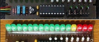
Digital ammeter circuit
Any digital ammeter circuit includes a microcontroller with a built-in ADC (analog-to-digital converter). It also implies output to a liquid crystal LED screen. The design of such an ammeter uses resistors of various resistances (depending on the range of the current being measured) and stabilizers (for selective devices). The liquid crystal display and microcontroller in the ammeter are usually combined into a so-called digital measuring head (DMG).
This head works to measure both current and voltage levels. Their main advantage over traditional indicators used in older analog devices is high accuracy, although the digital measuring head requires an additional power source.
A separate category of ammeters includes a demonstration device for laboratories and scientific classrooms, which has a wide measurement range (0.01–9.99 A) and usually has a galvanometer mode.
Measuring devices in an apartment or office electrical panel
In a specialized switchboard at the entrance, switches, circuit breakers, and other components of the distribution system are installed. If duties are performed flawlessly, the supplying organization provides power within standard parameters. However, sometimes additional control is required.
If the voltage level is excessive, fuses, transformers, rectifier bridges and other components of the input units blow out. Low values are accompanied by a slowdown in the rotation of electric drives and a decrease in productivity. A modern voltmeter is capable of not only indicating actual values, but also recording readings in memory. This data will help identify the source of problems when typical failures occur.
The ammeter shows the current strength. This device checks the actual consumption of different loads. Such products are needed for high-quality balancing of air conditioners, ovens, machine tools, heat guns and other powerful consumers.
For your information. Such solutions help to evenly distribute loads in three-phase 380 V networks.
Comprehensive information about current and voltage is obtained using combined instruments. An additional advantage of the voltammeter is its relative compactness. As a rule, this design is cheaper compared to two separate products.
Kinds
A single-phase voltmeter contains an electrical signal converter and a digital matrix. In addition to the main blocks and nodes, the device has a built-in Wi-Fi or 3G/4G module that sends data over the Internet with a certain response interval. Some device models can save minimum and maximum readings of voltage and current consumption for a given period of time, and also keep a “log” of power supply switches on and off.
A three-phase DIN voltmeter has the same control and monitoring modules and components as a single-phase one, but this module differs in that all three phases are required for its correct operation. If any of the phases is missing, a phase reversal has occurred, or the voltage is very different on one or all three phases, the device will record information about the network operation as one error or a series of errors that interfere with normal operation, and can simply turn off all three lines. A three-phase device also measures the parameters of each phase.
Installation and operation
Installation is carried out by mounting it on a DIN rail (35 mm wide) in the panel - or on a flat wall surface. No special fasteners are needed here - the parts are already included in the kit of the shield and the voltmeter itself. To use the DIN voltmeter on a flat wall, switch the lock tensioners to the extreme position. The terminal block allows you to securely fasten wires with a cross-sectional area of 0.5... 2.5 mm2. After connecting to the network and testing the operation, the voltammeter will immediately display the measured voltage and current consumption on the line (or all three lines). They do not require a separate source - they are powered from the same line.
Devices are most often equipped with one button, which combines the display of all information about the operation of the network:
- first press – maximum voltage since the last reset of the event log;
- the second is the minimum voltage on the line;
- third – voltage fluctuations (change in voltage);
- the fourth is the number of power outages.
Different current loads in individual models require connection to different terminals. This is necessary to obtain the required accuracy. Specific instructions are determined by one model or another.
Voltmeters with DIN mounting can produce a measurement error of up to 1.5%, are designed for industrial frequencies of 45... 70 Hz, have a voltage spread of 50–450 V and the 3rd level of stability according to GOST R-51317.4.4-99. Consume no more than 2.5 W. Service life - 8... 10 years, subject to the rules of use.
For information on the effective value voltmeter VM-1 on a 35 mm DIN rail, see below.