One of the most common components in electrical circuits is the non-polarized capacitor. They are used in the power supply, high-frequency device (capacitance with three terminals), in the audio circuit, etc.
In this article, we will not touch on the theoretical foundations of radio electronics in order to describe its operating principle. If you need to update your knowledge, this information is easy to find through search engines. Therefore, let's move directly to practical issues. Namely: how does a non-polar capacitance differ from a polar one, how to check the functionality of the element, markings, etc.
Non-polar electrolytic capacitor
Non-polar electrolytic capacitors can find use in equipment designed for DC power supply, where polarity reversal can easily occur when the plug is turned on.
Dry non-polar electrolytic capacitors have two anode foils molded into the same electrolyte at the same voltage. The manufacturing technology of such capacitors is no different from the manufacturing of polar capacitors. Some change in technology takes place when winding sections, since instead of the cathode foil, a second anode plate is laid.
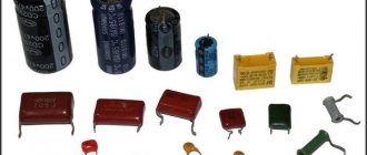
| Appearance of electrolytic capacitors. |
Non-polar electrolytic capacitors are also manufactured, in which both plates have an oxide layer.
Capacitors assembled as non-polar electrolytic capacitors can also be used for inclusion in an alternating current circuit.
Along with polar ones, there are dry non-polar electrolytic capacitors.
The industry also produces several types of non-polar electrolytic capacitors, in which the oxide layer is deposited on both electrodes.
Capacitance and dissipation tangent measurements of non-polar electrolytic capacitors and AC electrolytic capacitors are performed using the same methods as measurements of polar electrolytic capacitors. For these measurements, applying a DC polarizing voltage to the capacitors is not necessary.
As was shown in the fourth chapter, the capacitance of a non-polar electrolytic capacitor with the same plate area is half the capacitance of a conventional polar electrolytic capacitor.
Along with conventional polar capacitors, non-polar electrolytic capacitors can also be manufactured, in which a second anode is used instead of a cathode.
The polarity of high level signals must be unambiguous, or non-polar electrolytic capacitors must be used.
Capacitors with such plates do not require polarity when connected to an electrical circuit; Accordingly, they are called non-polar electrolytic capacitors.
As will be shown below, it is also possible to manufacture non-polar electrolytic capacitors, which do not require polarity when connected to a DC circuit. The production of a non-polar electrolytic capacitor designed for long-term operation at alternating voltage is hampered by the large tg 8 characteristic of capacitors of this type.
| Charge distribution in a non-polar electrolytic capacitor. a - at the moment when the voltage passes through a maximum, b - at the moment when the voltage is zero. |
Thus, only half of the total charge that was bound at the boundaries of the oxide layer when the voltage across the capacitor was at its maximum value can go into the external circuit. This circumstance leads to the fact that the capacitance of a non-polar electrolytic capacitor is half that of a polar capacitor that has the same anode surface as each plate of the non-polar capacitor.
By appearance
The polarity designation symbols may vary depending on the manufacturer and the time of manufacture of the radio component. It is clear that over time, regulations defining the standardization system change. How to find out the polarity:
- In the former USSR countries, it was customary to designate only the positive terminal on such devices. On the body you need to find the “+” sign; the end to which it is closest is the anode. Accordingly, the second one is a minus. Czech capacitors of older releases have similar markings;
- The bottom of electrolytic capacitors type K50-16 is made of plastic, where the polarity is written. There are cases where the plus and minus signs are placed so that the terminals intersect their centers;
- There are also devices of non-standard design that provide connection to the chassis. They have mainly found application in lighting lamps, namely in anode voltage filters (always positive). Such capacitors have a plate - the cathode is connected negatively and is brought out to the body, and the anode is a terminal coming out of the element;
Note! This type may have completely opposite polarity, so be sure to study the markings on the device.
- Often the discontinued series of ETO capacitors are confused with diodes in appearance. They are also marked, but if the markings are erased, then the end that comes out of the thickening of the body is the anode. Such devices cannot be disassembled; they contain harmful substances;
- The polarity of current electrolytic capacitors of various designs can be easily determined by the stripe near the minus terminal. Usually it is made as a broken line and applied with bright paint.
By appearance, one can also conclude about the polarity: a longer leg (lead) means “plus”.
Expert opinion
Viktor Pavlovich Strebizh, lighting and electrical expert
Any questions ask me, I will help!
Electrolytic capacitors have a higher capacitance, but for most purposes non-polar capacitors are preferred. If there is something you don’t understand, write to me!
Flat capacitor and its capacity
A parallel plate capacitor is a capacitor that consists of two identical plates that are parallel to each other. The plates can be of different shapes. In practice, you can most often find square, rectangular and round plates. Let's look at a simple flat square capacitor.
flat capacitor
Where
d – distance between the capacitor plates, m
S – area of the smallest plate, m2
ε – dielectric constant of the dielectric between the plates of the capacitor
The finished formula for a flat capacitor will look like this:
Where
C – capacitor capacity, f
ε – dielectric constant of the dielectric
ε0 – dielectric constant, f/m
S – area of the smallest plate, m2
d – distance between plates, m
Yes, I know, the question immediately arises in your mind: “What is the dielectric constant?” The dielectric constant is a constant value that is needed for calculations in some electromagnetism formulas. Its value is 8.854 × 10⁻¹² f/m.
Dielectric constant - this value depends on the type of dielectric that is located between the plates of the capacitor. For example, for air and vacuum this value is 1; for some other substances you can look at the table.
What conclusion can be drawn from this formula? If you want to make a capacitor with a huge capacity, make the area of the plates as large as possible, the distance between the plates as small as possible, and use distilled water instead of the dielectric.
Currently, capacitors are made from several plates in the form of a layer cake. It roughly looks like this.
multilayer capacitor
In this case, the formula of such a capacitor will take the form:
multilayer capacitor formula
where n is the number of plates
Capacitor positive symbol
On domestic Soviet products, only the positive contact was indicated with a “+” sign. This sign was applied to the case next to the positive terminal. Sometimes in the literature the positive terminal of electrolytic capacitors is called the anode, since they not only passively accumulate charge, but are also used to filter alternating current, i.e. have the properties of an active semiconductor device. In some cases, the “+” sign is also placed on the printed circuit board, close to the positive terminal of the drive located on it.
On products of the K50-16 series, polarity markings are applied to the bottom, made of plastic. For other models of the K50 series, for example K50-6, the “plus” sign is painted on the bottom of the aluminum case, next to the positive terminal. Sometimes imported products produced in the countries of the former socialist camp are also marked on the bottom. Modern domestic products meet global standards.
The marking of SMD (Surface Mounted Device) capacitors intended for surface mounting (SMT - Surface Mount Technology) differs from ordinary ones. Flat models have a black or brown body in the form of a small rectangular plate, part of which at the positive terminal is painted over with a silver stripe with a plus sign on it.
What is a capacitor?
A device that stores electricity in the form of electrical charges is called a capacitor.
The amount of electricity or electric charge in physics is measured in coulombs (C). Electrical capacitance is calculated in farads (F).
A solitary conductor with an electrical capacity of 1 farad is a metal ball with a radius equal to 13 radii of the Sun. Therefore, a capacitor includes at least 2 conductors, which are separated by a dielectric. In simple device designs, paper is used.
The operation of a capacitor in a DC circuit is carried out when the power is turned on and off. Only during transient moments does the potential on the plates change.
The capacitor in the AC circuit recharges at a frequency equal to the frequency of the power source voltage. As a result of continuous charges and discharges, current flows through the element. A higher frequency means the device recharges faster.
The resistance of the circuit with a capacitor depends on the frequency of the current. At zero frequency of direct current, the resistance value tends to infinity. As the AC frequency increases, the resistance decreases.
Charging and discharging a capacitor - RC circuit
Now let's look at the processes occurring inside the capacitor during charge and discharge. To do this, consider the simplest electrical circuit with a capacitor. On the left side of the diagram we connect the power source. We will place the switch and resistor on top, and the capacitor itself on the right. The section of the circuit that contains a capacitor and resistor is called an RC circuit.
When we disconnect the capacitor from the power source, this same leakage current will gradually discharge the capacitor. This feature of electrical capacitors prevents us from making them into containers for long-term energy storage. Although ionistors partially solve this problem.
What is the difference between a polar and non-polar capacitor
The main difference between these two types is the structure of the dielectric, more precisely, its interface with the plate. For clarity, we suggest looking at Figure 1, which shows a non-polar ceramic capacitor.
Figure 1. Construction of a ceramic container in an SMD package
Designation of structural elements:
- A – contact electrodes;
- B – coating;
- C – dielectric;
- D – internal electrodes.
As can be seen from the figure, the boundary between the dielectric and the plate is homogeneous, and, accordingly, the interaction between them is the same. Therefore, this type of element does not require polarity during installation.
As for electrolytic (polar) capacitors, the structure of the transition between the plate and the dielectric is different for each side of the latter (cathode and anode). Moreover, the differences are expressed both in physical properties and chemical composition. As an example, let's look at how tantalum electrolytic containers are designed.
Polar type tantalum capacitor design
Designations:
- A – mark marking the anode contact;
- B – anode contact plate;
- C – internal anode based on granulated tantalum; the oxide of this chemical element (Ta2O5), formed during operation, acts as a dielectric;
- D – manganese dioxide electrolyte (MnO2);
- E – internal cathode (a mixture of silver and graphite);
- F – silver-based adhesive connecting the internal cathode to the contact plate;
- G – cathode contact plate;
- H – compound coating.
When installing this type of container, polarity must be observed. Otherwise, the element will not perform its functions. Therefore, electrolytic containers can only be used in a direct current (or pulsed) circuit. The use of alternating voltage in the circuit is also permissible if the inclusion of electrolytes meets certain conditions. We will discuss below whether it is possible to replace the electrolyte with a non-polar container.
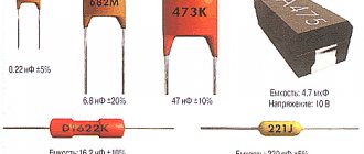
Marking
The capacity designation on such products consists of three numbers. The last one shows the number of zeros, the other two show the parameter value in picofarads. For example, if the device has the numbers 123, the capacitance can be calculated as follows: 12 pF and 3 zeros - 12,000 pF, that is, 0.012 μF. The marking of low-capacity elements (less than 10 pF) is distinguished by the use of the Latin letter R as a symbol separating the integer and fractional parts of the number.
Non-polar ceramic products for SMD installation are not marked at all. The capacitance of such components can range from 1 pF to 10 µF. Tantalum and aluminum elements have a digital or alphanumeric coding. They differ in the shape of the body: in the first it is rectangular, in the second it is cylindrical.
Being less demanding on connection conditions than polarized products, non-polar elements are widely used when installing electrical circuits. They are able to work correctly anywhere in the electrical circuit and provide the required capacitance value.
Features of the design and inclusion of NEC
Electrolytic capacitor
A distinctive feature of such products is the absence of a constant displacement of electron masses on the plate elements. This is achieved due to the fact that aluminum parts undergo oxidation on both sides of the dielectric.
Design
Due to their structural features, the devices under consideration can be compared to a pair of back-to-back polar electrolytic cells that have no charge on the plating surfaces. Therefore, when such a capacitor is connected to a circuit, there is no need for a rigid connection to the potentials. Thus, these products are able to function in different parts of the electrical circuit and maintain the required capacitance parameters.
Features of inclusion
If you switch the positive and negative terminals when connecting a polarized device, it will not be able to charge and discharge. Therefore, such an element will not work normally. Non-polar electrolytic devices are capable of operating when connected to different circuits without regard to polarity. This is due to their structure - they do not have an anode and a cathode (plates with negative and positive charges).
In addition to electrolytic devices, there is another type of non-polar devices. Their design includes a pair of covering surfaces (without polarization) with a dielectric mounted between them. In electrical circuits, such parts are placed in the role of low-capacity elements with the functions of dividing the current into components, blocking and setting time.
The capacitor is non-polar and polar. Mikhail Nikolaenko - Self-instruction manual on radio electronics
- the measuring device is switched to ohmmeter mode;
- The ohmmeter is set to the upper resistance measurement mode - infinity value;
- the resistance of the device is measured at the terminals - if the device shows a low resistance value (any other than the “infinity” value), then the element under test is unsuitable for further operation; there is a dielectric breakdown or electrolyte leakage inside.
Useful tips Connection diagrams Principles of operation of devices Main concepts Meters from Energomer Precautions Incandescent lamps Video instructions for the master Testing with a multimeter
Polymer (solid state) capacitors
Rice. 8. Polymer (solid-state) capacitors
Description: Solid capacitors are polarized like other electrolytic capacitors but have several advantages such as lower losses due to low series resistance ESR and long lifespan. For conventional aluminum electrolytes, there is a risk of the electrolyte drying out at low temperatures, but solid-state capacitors, due to the use of a solid polymer dielectric, are highly reliable even at very low temperatures.
Applications: Used as a replacement for electrolytes in high-end motherboards and DC/DC converters.
Characteristic signs of electrolyte malfunction
These signs include:
- The device does not turn on. The power supply goes into protection or does not start;
- The device turns on but immediately turns off. The capacitance of the capacitors has dried out or lost its previous value, so the power supply goes into protection;
- Before the malfunction there was a squeaking sound in the power supply. This usually means that the capacitor has lost its seal and the electrolyte begins to leak;
- There is no brightness adjustment on the monitor. The lack of the required capacity leads to disruption of the entire device. The capacity in this case does the setting function;
- Before the malfunction there was an explosion and an unpleasant smell. The unpleasant odor is an electrolyte;
- The device turns on once. This means that there is a high probability of the power filter leaking.
External signs of malfunction of electrolytic capacitors:
- Bloating of the body;
- Hull damage:
- Presence of electrolyte under the housing;
- Swelling on the side of the contacts (at the bottom of the case, usually barely noticeable).
Also, high-frequency pulsations harm electrolytes. Therefore, most often they fail in power supplies, since that is where there is a lot of ripple.
Rules for working with electrolytes
Attention! Before touching the board of a faulty source, make sure that the capacitors are discharged. Even if the converter is faulty and not the electrolyte, the capacitors can be charged
They simply have nowhere to put their charge. Therefore, first of all, carefully and without touching the multimeter probe, measure the capacitances with high voltage. If they are charged, discharge them using a light bulb.
How to change old to new
There are two opinions among electronics engineers. The first thing is that you need to replace a faulty old capacitor with an equally old one. This is explained by the fact that the entire operation of the circuit has become “accustomed” to the old capacitor.
But the technically correct and well-founded opinion is that you need to install only a new capacitor that meets the parameters. There is no addictive pattern. Yes, many components are outdated and cannot work as before, but the capacitor essentially has nothing that would radically affect the deterioration of the performance of all circuits. On the contrary, the device will work better.
Replace old capacitors with new ones that are as close as possible in parameters. For example, you can take a little more capacity if we are talking about a power supply. And if this is a tuning circuit, then by increasing or decreasing the capacitance, you can influence the entire operating mode of the circuit. You need to act according to the situation.
Also, do not forget about such a parameter as ESR (equivalent series resistance).
Post Views: 693
Kinds
"Electrolytes" are divided into the following types of elements:
- aluminum;
- tantalum;
- niobium.
Each type is designed for specific operating conditions.
Aluminum Electrolytic Capacitors (EC)
Aluminum EC includes two tapes of aluminum foil and paper impregnated with electrolyte. All this is rolled up and placed in a metal case. The dielectric in this part is aluminum oxide. To increase the surface area, the foil is etched in a live electrolyte. At the same time, the capacity increases many times. The structure is hermetically sealed with rubber gaskets.
For your information. The second strip of foil is needed to improve contact with the electrolyte (cathode) and to form a negative terminal.
Tantalum capacitors
The size of such ECs is small, which allows them to be used in surface-mounted printed circuit boards. Tantalum is used as an anode. It has a porous structure and gives a large working area. The dielectric is tantalum oxide – Ta2O5. The layer is formed by placing the workpiece in a high-temperature acid solution, after which a current is passed through it. By adjusting the current, the thickness of the film is controlled. The cathode is manganese dioxide. The workpiece is soaked in a solution of Mn(NO3)2 (manganese nitrate) and dried.
Interesting. The cathode terminal is made by covering a layer of manganese dioxide with graphite, which, in turn, is covered with a layer of silver. After that, a tap is soldered to the silver to install the element leads into the holes on the board. When manufacturing polar SMD capacitors, the lead-contact is molded from silver-plated epoxy resin.
Tantalum EC
Niobium capacitors
In cells of this type, niobium is used as the anode. The rest of the technology and properties of such two-terminal devices are similar to their tantalum counterparts.
Niobium EC
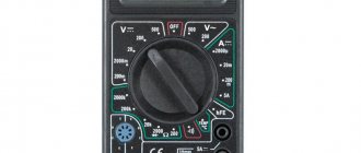
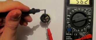
Capacitance measurement in resistance mode
Measurement in resistance mode
The multimeter switch should be set to resistance (ohmmeter) mode. In this mode, you can see if there is a break or short circuit inside the capacitor. To test a non-polar capacitor, the measurement range is set to 2 MOhm. For a polar product, a resistance of 200 Ohms is set, since at 2 MOhms charging will occur quickly.
The capacitor itself needs to be unsoldered from the circuit and placed on the table. Use the multimeter probes to touch the capacitor leads, observing the polarity. In non-polar parts, it is not necessary to observe plus and minus.
Measurement in resistance mode
When the probes touch the legs, the display will show a value that will increase. This is because the multitester will charge the component. After some time, the value on the screen will reach one - this means that the device is working. If 1 lights up immediately during testing, there is a break inside the device and it should be replaced. A zero value on the display indicates that a short circuit has occurred inside the capacitor.
If a non-polar capacitor is being tested, the value should be higher than 2. Otherwise, the device is not working.
Analog device
The above algorithm is suitable for a digital tester. When using an analog device, checking is even simpler - you only need to observe the movement of the arrow. The probes are connected in the same way, the mode is resistance testing. Smooth movement of the arrow indicates that the capacitor is working properly. The minimum and maximum values when connected indicate a breakdown of the electronic part.
It is important to note that testing in ohmmeter mode is carried out for parts with a capacitance above 0.25 µF. For smaller denominations, special LC meters or high-resolution testers are used
Polar and non-polar capacitors - what is the difference
All kinds of capacitors, used today almost everywhere in electronics and electrical engineering, contain various substances as dielectrics
However, with regard specifically to electrolytic capacitors, in particular also tantalum and polymer ones, when they are included in the circuit, it is important to strictly observe polarity. If such a capacitor is connected incorrectly to the circuit, it will not be able to work normally.
These capacitors are therefore called polar capacitors. What is the fundamental difference between a polar capacitor and a non-polar one? Why is it that some capacitors do not care how they are included in the circuit, while for others it is fundamentally important to maintain polarity?
Let's try to figure this out now. The point here is that the manufacturing process for electrolytic capacitors is very different from, say, ceramic or polypropylene. If for the latter two both the plates and the dielectric are homogeneous in relation to each other, that is, there is no difference in the structure at the plate-dielectric interface on both sides of the dielectric, then electrolytic capacitors (cylindrical aluminum, tantalum, polymer) have a difference in the structure of the dielectric transition -plating on both sides of the dielectric: the anode and cathode differ in chemical composition and physical properties.
When an electrolytic aluminum capacitor is made, they do not simply roll up two identical foil plates lined with electrolyte-impregnated paper. On the side of the anode plate (to which + is applied) there is a layer of aluminum oxide applied to the etched surface of the foil in a special way. The anode is designed to give electrons through an external circuit to the cathode during the charging of the capacitor. The negative plate (cathode) is simply aluminum foil; during the charging process, electrons come to it through an external circuit. The electrolyte here serves as a conductor of ions.
Polar and non-polar capacitors.
The same is the case with tantalum capacitors, where tantalum powder serves as the anode, on which a film of tantalum pentoxide is formed (the anode is connected to the oxide!), which functions as a dielectric, then there is a layer of semiconductor - manganese dioxide as an electrolyte, then a silver cathode, from which electrons will leave during the discharge process.
Polymer electrolytic capacitors use a lightweight conductive polymer as the cathode, but otherwise the processes are similar. The essence is oxidation and reduction reactions, like in a battery. The anode is oxidized during the electrochemical discharge reaction, and the cathode is reduced.
When an electrolytic capacitor is charged, there is an excess of electrons at its cathode, on the negative plate, imparting a negative charge to this terminal, and at the anode, a lack of electrons, giving a positive charge, thus obtaining a potential difference. If a charged electrolytic capacitor is connected to an external circuit, then excess electrons will run from the negatively charged cathode to the positively charged anode, and the charge will be neutralized. In the electrolyte, positive ions move at this moment from the cathode to the anode.
If such a polar capacitor is connected incorrectly to the circuit, then the described reactions will not be able to proceed normally, and the capacitor will not work normally. Non-polar capacitors can operate in any connection, since they have neither an anode, nor a cathode, nor an electrolyte, and their plates interact with the dielectric in the same way as with the source.
Capacitor polarity.
But what if you only have polar electrolytic capacitors at hand, but you need to connect the capacitor to a current circuit with changing polarity? There is one trick for this. You need to take two identical polar electrolytic capacitors and connect them together in series with terminals of the same name. You will get one non-polar capacitor from two polar ones, the capacitance of which will be 2 times less than each of its two components.
On this basis, by the way, non-polar electrolytic capacitors are made, in which an oxide layer is present on both plates. For this reason, non-polar electrolytic capacitors are significantly larger than polar capacitors of similar capacity. Based on this principle, electrolytic starting non-polar capacitors are also manufactured, designed to operate in alternating current circuits with a frequency of 50-60 Hz.
Polar and non-polar capacitor
By labeling
Labeling of charge storage devices, including electrolytic ones, depends on the country, manufacturer and standards, which change over time. Therefore, the question of how to determine the polarity on a capacitor does not always have a simple answer.
Capacitors are used in almost all modern devices: subwoofers, electric motors, cars, pumps, power tools, air conditioners, refrigerators, mobile phones, etc.
Depending on the functions performed, they are divided into general purpose and highly specialized.
General purpose capacitors include low-voltage storage devices that are used in most types of electrical equipment.
Highly specialized ones include high-voltage, pulse, noise suppression, dosimetric and start-up capacitors.
Expert opinion
Viktor Pavlovich Strebizh, lighting and electrical expert
Any questions ask me, I will help!
If a charged electrolytic capacitor is connected to an external circuit, then excess electrons will run from the negatively charged cathode to the positively charged anode, and the charge will be neutralized. If there is something you don’t understand, write to me!
General information
Capacitors are designed to store electrical energy and release it when necessary. These passive electronic components are divided into types:
- constant capacitor;
- variable capacitor.
The main characteristic of the element is capacity. It is designated by the letter C and is measured in farads.
Important! A unit of capacity 1 F is a very large value. Parts used in practice have capacitance measured in microfarads (µF), picofarads (pF), nanofarads (nF)
The graphic designation on the diagrams looks like two parallel vertical lines separated by a space.
The device of a capacitive two-terminal network of constant and variable capacitance
This is exactly how a conventional capacitor is designed. Between the two plates (plates) there is an air gap - a dielectric. The capacity value directly depends on the size of the plates and the distance between them.
The operation of variable capacitors is based on changing the distance between the plates. The moving plates are the rotor, the stationary plates are the stator. There are vacuum variable capacitive elements. The device is placed in a flask from which air has been pumped out.
Graphic designation on diagrams
Code marking, addition
According to IEC standards, in practice there are four ways to encode the nominal capacity.
A. 3-digit marking
The first two digits indicate the capacitance value in pygofarads (pf), the last one indicates the number of zeros. When the capacitor has a capacitance of less than 10 pF, the last digit may be "9". For capacitances less than 1.0 pF, the first digit is “0”. The letter R is used as a decimal point. For example, code 010 is 1.0 pF, code 0R5 is 0.5 pF.
| Code | Capacitance [pF] | Capacitance [nF] | Capacitance [µF] |
| 109 | 1,0 | 0,001 | 0,000001 |
| 159 | 1,5 | 0,0015 | 0,000001 |
| 229 | 2,2 | 0,0022 | 0,000001 |
| 339 | 3,3 | 0,0033 | 0,000001 |
| 479 | 4,7 | 0,0047 | 0,000001 |
| 689 | 6,8 | 0,0068 | 0,000001 |
| 100* | 10 | 0,01 | 0,00001 |
| 150 | 15 | 0,015 | 0,000015 |
| 220 | 22 | 0,022 | 0,000022 |
| 330 | 33 | 0,033 | 0,000033 |
| 470 | 47 | 0,047 | 0,000047 |
| 680 | 68 | 0,068 | 0,000068 |
| 101 | 100 | 0,1 | 0,0001 |
| 151 | 150 | 0,15 | 0,00015 |
| 221 | 220 | 0,22 | 0,00022 |
| 331 | 330 | 0,33 | 0,00033 |
| 471 | 470 | 0,47 | 0,00047 |
| 681 | 680 | 0,68 | 0,00068 |
| 102 | 1000 | 1,0 | 0,001 |
| 152 | 1500 | 1,5 | 0,0015 |
| 222 | 2200 | 2,2 | 0,0022 |
| 332 | 3300 | 3,3 | 0,0033 |
| 472 | 4700 | 4,7 | 0,0047 |
| 682 | 6800 | 6,8 | 0,0068 |
| 103 | 10000 | 10 | 0,01 |
| 153 | 15000 | 15 | 0,015 |
| 223 | 22000 | 22 | 0,022 |
| 333 | 33000 | 33 | 0,033 |
| 473 | 47000 | 47 | 0,047 |
| 683 | 68000 | 68 | 0,068 |
| 104 | 100000 | 100 | 0,1 |
| 154 | 150000 | 150 | 0,15 |
| 224 | 220000 | 220 | 0,22 |
| 334 | 330000 | 330 | 0,33 |
| 474 | 470000 | 470 | 0,47 |
| 684 | 680000 | 680 | 0,68 |
| 105 | 1000000 | 1000 | 1,0 |
* Sometimes the last zero is not indicated.
B. 4-digit marking
4-digit coding options are possible. But even in this case, the last digit indicates the number of zeros, and the first three indicate the capacity in picofarads.
| Code | Capacitance[pF] | Capacitance[nF] | Capacitance[uF] |
| 1622 | 16200 | 16,2 | 0,0162 |
| 4753 | 475000 | 475 | 0,475 |
C. Capacitance marking in microfarads
The letter R may be used instead of the decimal point.
| Code | Capacitance [µF] |
| R1 | 0,1 |
| R47 | 0,47 |
| 1 | 1,0 |
| 4R7 | 4,7 |
| 10 | 10 |
| 100 | 100 |
D. Mixed alphanumeric marking of capacity, tolerance, TKE, operating voltage
Unlike the first three parameters, which are marked in accordance with standards, the operating voltage of different companies has different alphanumeric markings.
| Code | Capacity |
| p10 | 0.1 pF |
| IP5 | 1.5 pF |
| 332p | 332 pF |
| 1NO or 1nO | 1.0 nF |
| 15H or 15n | 15 nF |
| 33H2 or 33n2 | 33.2 nF |
| 590H or 590n | 590 nF |
| m15 | 0.15uF |
| 1m5 | 1.5 µF |
| 33m2 | 33.2 µF |
| 330m | 330 µF |
| 1mO | 1 mF or 1000 μF |
| 10m | 10 mF |
Code marking of electrolytic capacitors for surface mounting
The following coding principles are used by such well-known companies as Hitachi and others. There are three main coding methods:
A. Marking with 2 or 3 characters
The code contains two or three characters (letters or numbers) indicating the operating voltage and rated capacity. Moreover, the letters indicate voltage and capacitance, and the number indicates the multiplier. In the case of a two-digit designation, the operating voltage code is not indicated.
| Code | Capacitance [µF] | Voltage [V] |
| A6 | 1,0 | 16/35 |
| A7 | 10 | 4 |
| AA7 | 10 | 10 |
| AE7 | 15 | 10 |
| AJ6 | 2,2 | 10 |
| AJ7 | 22 | 10 |
| AN6 | 3,3 | 10 |
| AN7 | 33 | 10 |
| AS6 | 4,7 | 10 |
| AW6 | 6,8 | 10 |
| CA7 | 10 | 16 |
| CE6 | 1,5 | 16 |
| CE7 | 15 | 16 |
| CJ6 | 2,2 | 16 |
| CN6 | 3,3 | 16 |
| CS6 | 4,7 | 16 |
| CW6 | 6,8 | 16 |
| DA6 | 1,0 | 20 |
| DA7 | 10 | 20 |
| DE6 | 1,5 | 20 |
| DJ6 | 2,2 | 20 |
| DN6 | 3,3 | 20 |
| DS6 | 4,7 | 20 |
| DW6 | 6,8 | 20 |
| E6 | 1,5 | 10/25 |
| EA6 | 1,0 | 25 |
| EE6 | 1,5 | 25 |
| EJ6 | 2,2 | 25 |
| EN6 | 3,3 | 25 |
| ES6 | 4,7 | 25 |
| EW5 | 0,68 | 25 |
| GA7 | 10 | 4 |
| GE7 | 15 | 4 |
| GJ7 | 22 | 4 |
| GN7 | 33 | 4 |
| GS6 | 4,7 | 4 |
| GS7 | 47 | 4 |
| GW6 | 6,8 | 4 |
| GW7 | 68 | 4 |
| J6 | 2,2 | 6,3/7/20 |
| JA7 | 10 | 6,3/7 |
| JE7 | 15 | 6,3/7 |
| JJ7 | 22 | 6,3/7 |
| JN6 | 3,3 | 6,3/7 |
| JN7 | 33 | 6,3/7 |
| JS6 | 4,7 | 6,3/7 |
| JS7 | 47 | 6,3/7 |
| JW6 | 6,8 | 6,3/7 |
| N5 | 0,33 | 35 |
| N6 | 3,3 | 4/16 |
| S5 | 0,47 | 25/35 |
| VA6 | 1,0 | 35 |
| VE6 | 1,5 | 35 |
| VJ6 | 2,2 | 35 |
| VN6 | 3,3 | 35 |
| VS5 | 0,47 | 35 |
| VW5 | 0,68 | 35 |
| W5 | 0,68 | 20/35 |
B. 4-character marking
The code contains four characters (letters and numbers) indicating the capacity and operating voltage. The first letter indicates the operating voltage, the subsequent digits indicate the nominal capacitance in picofarads (pF), and the last digit indicates the number of zeros. There are 2 options for encoding the capacity: a) the first two digits indicate the nominal value in picofarads, the third - the number of zeros; b) the capacitance is indicated in microfarads, the m sign acts as a decimal point. Below are examples of marking capacitors with a capacity of 4.7 μF and an operating voltage of 10 V.
Read also: Controlling a triac from a microcontroller
C. Two-line marking
If the size of the case allows, then the code is located in two lines: the capacitance rating is indicated on the top line, and the operating voltage is indicated on the second line. Capacitance can be indicated directly in microfarads (µF) or in picofarads (pf) indicating the number of zeros (see method B). For example, the first line is 15, the second line is 35V - means that the capacitor has a capacity of 15 uF and an operating voltage of 35 V.
This article was produced by our experienced team of editors and researchers, who reviewed it for accuracy and comprehensiveness.
Number of sources used in this article: 23. You will find a list of them at the bottom of the page.
wikiHow's content management team carefully monitors the work of its editors to ensure that every article meets our high quality standards.
The markings of capacitors are more varied than the markings of resistors. It is quite difficult to see the markings on small capacitors because the surface area of their housings is very small. This article tells you how to read the labels of almost all types of modern capacitors manufactured abroad. The markings on your capacitor may be in a different order (compared to those described in this article). Moreover, some capacitors do not have voltage and tolerance values - you only need the capacitance value to create a low voltage circuit.
Many types of electrical capacitors do not have polarity and therefore their inclusion in a circuit is not difficult. Electrolytic charge storage devices constitute a special class, because... have positive and negative terminals, so when connecting them, the problem often arises - how to determine the polarity of the capacitor.
Life Test Results of Electrolytic Capacitors
Double-terminal circuits of the same batch and the same type are tested. They are located in a thermostat in which the operating temperature is maintained. A current is passed through the elements, the voltage value of which is equal to Unom. The connection is made in the correct polarity. Separately, parts are tested by passing an alternating current of a given frequency and amplitude. During the test, all main and parasitic parameters are periodically monitored.
Based on the results, a calculation is made of the durability and number of hours without failures. An excellent result is 1 failure per hour for a batch of 1 billion parts.
Before checking the capacitor
Because Capacitors accumulate electrical charge and should be discharged before testing. This can be done with a screwdriver - you need to touch the terminals with the tip to create a spark. Then you can ring the component. Checking the capacitor can be done either with a multitester or with the help of light bulbs and wires. The first method is more reliable and provides more accurate information about the electronic element.
Before starting the test, you should inspect the capacitor. If it has cracks, insulation damage, leaks or swelling, the internal electrolyte is damaged and the device is broken. It needs to be replaced with a working device. If there is no external damage, you will have to use a multimeter.
Before taking measurements, you need to determine the type of capacitor - polar or non-polar. The first one must have correct polarity, otherwise the device will fail. In the second case, determining the plus and minus outputs is not required, but measurements will be carried out using a different technology.
You can determine the polarity by the mark on the case. The part should have a black stripe indicating zero. On the side of this leg there is a negative contact, and on the opposite side there is a positive one.
Parameters that characterize capacitors
Generally speaking, there are many such parameters. We are not having a Nobel lecture here, so we will limit ourselves to only the necessary minimum, which will be useful in practical activities. Rated operating voltage. The capacitor can be used in modes when the voltage across it does not exceed the operating voltage. For example, you can use an electrolytic capacitor with an operating voltage of 10 V in +5 V or +3 V circuits.
The higher the operating voltage of an electrolytic capacitor with equal capacity, the larger its dimensions. The operating voltage on ceramic and other capacitors may not be explicitly stated or not stated at all - especially if the capacitor is small. ESR (Equivalent Series Resistance) - equivalent series resistance. The capacitor terminals and their contacts with the plates have non-zero, although very small, resistance. This resistance is active, therefore, in accordance with Ohm's and Joule-Lenz's laws, when current flows through this resistance, heat will be dissipated.
Marking of capacitors.
This will cause the capacitor to heat up. Therefore, electrolytic capacitors usually indicate the maximum operating temperature. Computer power supplies and motherboards use special capacitors with reduced ESR. The ESR value for such capacitors can range from hundredths to tenths of an Ohm. What happens if instead of a capacitor with a reduced ESR when repairing power supplies or motherboards, you use a regular one? It will work for a while. But since its ESR is greater, more current will flow through the circuit of such a capacitor, which will cause accelerated degradation of the capacitor. Therefore, it will quickly fail.
The ESR value can be determined by special markings (most often 2 Latin letters) on the capacitor body. The correspondence of these letters to real ESR values is indicated in the datasheet.
What happens if you reverse the polarity?
If you make a mistake with the polarity of an electrolytic capacitor, it will definitely fail! The resistance of the capacitor with reverse polarity is small, so a significant current will flow through its circuit. This will cause rapid overheating, boiling of the electrolyte, the vapors of which will rupture the housing. The same effect will be caused by an increase in operating voltage above that indicated on the case. To eliminate bad consequences, the top cover of the case is made profiled, with grooves-recesses on the top cover.
It will be interesting➡ What are flat capacitors
With increased pressure inside, the lid diverges along these grooves, releasing vapors out. It should be noted that electrolytic capacitors used in computer power supplies and motherboards may fail after several years of normal operating conditions. The fact is that in capacitors, due to the presence of electrolyte, electrochemical processes constantly occur, aggravated by heavy operating conditions and elevated temperatures.
Characteristics and properties
Capacitor parameters that are used to create and repair electronic devices include:
- Capacity - C. Determines the amount of charge that the device holds. The value of the nominal capacity is indicated on the case. To create the required values, the elements are included in the circuit in parallel or in series. Operational values do not coincide with calculated values.
- Resonant frequency - fр. If the current frequency is greater than the resonant one, then the inductive properties of the element appear. This makes work difficult. To ensure the design power in the circuit, it is reasonable to use a capacitor at frequencies below resonant values.
- Rated voltage - Un. To prevent breakdown of the element, the operating voltage is set less than the rated voltage. The parameter is indicated on the capacitor body.
- Polarity. If the connection is incorrect, breakdown and failure will occur.
- Electrical insulation resistance - Rd. Determines the leakage current of the device. In devices, parts are located close to each other. At high leakage current, parasitic connections in the circuits are possible. This leads to malfunctions. Leakage current worsens the capacitive properties of the element.
- Temperature coefficient - TKE. The value determines how the capacitance of the device changes with fluctuations in ambient temperature. The parameter is used when developing devices for operation in harsh climatic conditions.
- Parasitic piezoelectric effect. Some types of capacitors create noise in devices when deformed.
Tips and tricks
When starting to check elements, it is necessary to clearly understand that even the most modern multimeters are not capable of measuring the very large capacitance of such devices; in most cases, the maximum limit is the measurement of both polar and non-polar elements with a capacity of up to 200 µF (200uF).
It’s also a good idea for radio amateurs to remember about safety precautions when checking such high-voltage circuits.
Repair of household radio equipment that uses high-voltage circuits should begin after turning off the device and discharging the electronic component with a discharge circuit consisting of a resistor with a nominal value of 2 kOhm...1 MΩ, which is connected to the common wire of the circuit or housing:
- in low-voltage circuits with capacitances up to 1000 μF and voltages up to 400 V, 2 kOhm (25 W) is sufficient;
- for circuits with capacitances up to 2 μF and with average operating voltages up to 5000 V - 100 kOhm (25 W);
- for high-voltage circuits with capacitances up to 2 nF and operating voltages up to 50 kV - 1 MOhm (10 W).
Well, for extreme sports enthusiasts, the oldest method of checking large-capacity devices may well be suitable. After full charging, and the property of charging and accumulating a charge of electricity in this case will be of primary importance, the terminals of the element are closed to a metal object, and it is advisable not only to isolate the object itself, but also your hands with rubber gloves.
The result should appear in a unique spark and simultaneous sound accompaniment of the discharge process.
Expert opinion
Viktor Pavlovich Strebizh, lighting and electrical expert
Any questions ask me, I will help!
In the final part of the review, it is necessary to note another group of non-polar capacitors, the design of which includes only ordinary non-polarized plates with a dielectric placed between them. If there is something you don’t understand, write to me!
Types of capacitors by dielectric type
One of the most common components in electrical circuits is the non-polarized capacitor. They are used in a power supply, a high-frequency capacitance device with three terminals, in a sound circuit, etc. Within the framework of this article, we will not touch on the theoretical foundations of radio electronics in order to describe its operating principle. If you need to update your knowledge, this information is easy to find through search engines. Therefore, let's move directly to practical issues.
It is also very confusing that there are non-polar (II) capacitors there, even in those places K there are both polar and non-polar.
Replacing non-polar capacitors with polar ones - what do you need to know?
In fact, if you don’t have a non-polar capacitor at hand, but only polar capacitors, then you can replace them according to the following scheme:
- First you need to determine where exactly on the board is plus and where is minus, and then solder in a polar capacitor, observing the polarity;
- Use a circuit of two polar capacitors instead of one non-polar capacitor.
The second method is the most preferable, because it allows the beginner not to go too far into studying the nutritional plan. It is enough to connect two polar capacitors together to get one non-polar capacitor.
Two polar capacitors are connected with pluses, and the minus goes into the circuit. The result is one non-polar capacitor.
For example, we need to replace one 5 µF non-polar capacitor, but we don’t have it at hand. Then we take two polar capacitors of 10 μF each, connect them with pluses, and solder them into the board with minuses. There is no need to observe polarity, because from two polar capacitors we got one non-polar capacitor.
How to test a non-polar capacitor with a multimeter
The operation of radio electronics also involves troubleshooting equipment. Therefore, when considering non-polar capacitors, one cannot abstract from the topic of diagnosing their performance.
As practice shows, in most cases the cause of tank failure is breakdown, which leads to a decrease in leakage resistance. That is, the element practically becomes a conductor. Such a malfunction can often be determined by the appearance of the container (see Figure 5); if this does not help, you will need a simple digital or analog multimeter.
Figure 5. “Burnt” (broken) container
Using the device, you should measure the leakage resistance; in the working elements it should be infinitely large. The check is performed as follows:
- it is necessary to completely dismantle the part, or unsolder one of its terminals, in order to exclude the influence of other circuit elements on the multimeter readings;
- set the device to continuity testing or resistance measurement mode (select the maximum limit);
- we connect the probes to the output contacts (Figure 6), while trying not to touch them, otherwise the device will show skin resistance;
Figure 6. Connecting the capacitance to the measuring device
We carry out the measurement; if the capacitance is in good condition, one will be displayed on the screen (Figure 7), which indicates an infinitely large resistance between the plates.
Figure 7. The device in dialing mode shows an infinitely high resistance
Unfortunately, this method can only test the capacitance for breakdown; this method is not suitable for determining an internal break. In this case, you can distinguish a broken part from a functional one by measuring its capacity; some models of multimeters have this functionality. The principle of testing is practically the same as testing for breakdown, with the exception that the device must be switched to capacitance measurement mode.
How to determine a polar or non-polar capacitor - Yacht Club Ost-West
- The device switch is set to the resistance measurement position.
- Touch the probes to the terminals of the element. At this moment, the arrow shoots, showing low resistance (this is due to the charging process). Then the readings of the device change in the direction of increasing resistance.
- Change the polarity of the probes. The needle makes an even larger jump and returns to the high resistance position again. A discharge occurs and a subsequent charge occurs with the opposite polarity.
- The values of the maximum resistance are recorded for different polarities of connecting the probes of the device. A lower value indicates the presence of leakage currents, which means that the polarity of connecting the probes does not correspond to the purpose of the terminals. That is, if some resistance is detected, then the positive probe of the device is connected to the negative terminal of the capacitor. With correct polarity, a healthy element has negligible leakage currents, and the resistance approaches infinity.
What is the difference between a polar and non-polar capacitor
Polar capacitors have a pair of electrodes: positive and negative. In order for the device to function, polarity must be observed when connecting it to the electrical circuit. Otherwise, the element will quickly become unusable or even explode. Electrolytic storage devices of this type also have the features of a semiconductor element. These devices differ from non-polar devices by the presence of a significant difference in physical and chemical properties between the media on the two sides of the interface, which creates polarity. In the manufacture of both types of devices, conductive materials such as aluminum and tantalum are used.
Aluminum electrolytes
A non-polar electrolytic capacitor with aluminum plates differs from other products in its rather high inductance. It is formed due to twisting of the lining blanks for more convenient installation in the cylinder body. Despite the inexpediency of inductive phenomena in some cases, aluminum products are popular due to their low price and availability. They are manufactured in SMD form for mounting on the surface of a printed circuit board.
The main area of their application is leveling ripples in circuits where alternating current is rectified. Also, with the help of these devices, the pulsating electric current is divided into constant and variable components (this is used in devices that play sound recordings).
Important! When choosing a capacitor, it is advisable to choose a sample with a lower ESR (equivalent series resistance) value. This is especially critical for systems that require high-frequency ripple filtering (for example, a computer power supply)
Aluminum electrolyte capacitors
Tantalum based electrolytes
This material makes it possible to create high-capacity products that retain this property at significant operating voltages. Unlike the previous type, they have almost no inductance, which provides them with a greater range of applications. The products are small-sized, work stably, and last a long time. They are available in two housing versions, tailored for different types of installation. Smd options are designed to be placed on the surface of the board. They have high capacity with miniature sizes. The installation of such elements is carried out by robots. There are products equipped with long leads that are threaded into holes on the boards.
What is capacitor polarity and how to determine it?
- First you need to consider the voltage. If there is no element with a suitable rating, it is better to purchase a capacitor with a higher voltage. For example, if the original indicates 30 V, an analogue with a voltage of 40, 50, 65, 100 V is needed. There must be an increase. Analogues with lower voltage are not suitable, since they will not withstand the load and will explode. To obtain the required voltage, you can connect several capacitors in series.
- The second thing to consider is capacity. Often, if these are electrolytic capacitors, then you can use options with a larger capacity than the original. If you cannot find capacitors with the desired or higher rating, you can put several elements in parallel with a lower capacitance and get the desired rating.
JB Capacitors Film Capacitor Naming System
The JB Capacitors naming system for film capacitors (Figure 5) contains a number of fields:
- Main Series code;
- Sub-Series code (value 0 for all series except JFG, JFJ, JFR, JFS);
- operating voltage code (Voltage);
- nominal capacity code (Capacitance);
- capacitance tolerance code (Tolerance);
- pin pitch code (Pitch);
- lead length code (Lead Lengtch);
- Packing code.
Rice. 5. JB Capacitors Film Capacitor Naming System
So JFA02A102J050000B is a JFA series capacitor with an operating voltage of 100 V, a capacity of 1000 pF ±5%, a lead pitch of 5 mm, with a standard lead length (for JFA at least 20 mm), supplied without packaging.
The whole truth about capacitors: the magical properties of mysterious jars
Was there a better time to be a hi-fi enthusiast and lover than the late 1970s and early 1980s? On the one hand, there was so much happening with the development of digital audio, and on the other hand, there was an increase in subjectivity. Suddenly, turntables and amplifiers were judged not by their knock levels, output power, and harmonic distortion, but by how they sounded! And we could even talk seriously about the sound of the cables. In this new climate, everything that was once taken for granted in the field of hi-fi has become a candidate for re-evaluation.
The influence of passive electronic components - resistors, inductors and capacitors - on the sound has also been closely studied. Especially capacitors. Knowledgeable people began to discuss such phenomena as equivalent series resistance (ESR) and dielectric absorption.
Today we don't often hear about this topic, but not because the problem has been settled. Most likely, developers are now paying as much attention to the passive components they use as they are to the circuits in which they are used, so the public furor has died down somewhat.
Basics
In its simplest form, a capacitor consists of two metal plates separated by air (or, better yet, vacuum) and is shown schematically in Fig. 1. Since there is no conductive path between the plates, the capacitor blocks direct current (from a battery, for example). In this case, the capacitor, on the contrary, transmits alternating current signals - just such as sound waves.
Rice. 1. The components that make up a capacitor are two conducting plates separated by a dielectric layer.
Proven Solution
We don't often come across air capacitors, but if you've looked inside an old tube radio and seen the tuning element made up of alternating metal plates, that's a variable air capacitor. Most capacitors we encounter in audio and other electronics do not use air as the insulating material (dielectric) separating the plates because it has a low dielectric constant (1.0), meaning that air capacitors have a high capacitance too bulky to be practical. For this reason, mainly solid dielectrics with higher dielectric properties are used, including ceramics and various types of plastics (for example, PVC with a dielectric constant of 4.0). This is where the story gets especially interesting, since all of these dielectrics have some compromise in terms of their effect on sound, while air is almost perfect.
Simple filters
First, let's learn more about how capacitors behave and what they are used for. Capacitors block direct current and allow alternating current to pass, but they do not pass alternating current at different frequencies equally. This is explained by the fact that capacitors have reactance, which decreases with increasing frequency (by the way, inductors also have reactance, which, on the contrary, increases with increasing frequency).
Thus, capacitors pass high-frequency signals more easily than low-frequency signals, making them extremely useful in frequency-selective circuits (i.e., filters) and also for eliminating unwanted signals (such as hum or noise from a DC power supply).
Simple high- and low-pass filters are shown in Fig. 2. In a high-pass filter (Fig. 2a), a capacitor in series is connected to a shunt resistor. In the low pass filter (Figure 2b), the capacitor and resistor are swapped.
Rice. 2. RC filter of the first order of high (2a) and low (2b) frequencies.
So, capacitors are often used to combine circuits, isolate unwanted noise in DC circuits and in frequency selective circuits (filters). Because capacitors store electrical charge, large ones are also used as reservoirs in AC and DC power supplies. In Fig. Figure 3 shows a typical power supply that includes a step-down transformer (which steps down the line voltage), a bridge rectifier (which converts the AC current from the transformer to pulsed DC current), and a pair of reservoir capacitors (which smooth out the ripple after the AC is rectified).
Fig.3. Schematic diagram of a full-wave power supply consisting of a step-down transformer, a full-wave bridge rectifier and two reservoir capacitors.
Similar circuits are found in many solid-state audio components. Similar solutions are used in lamp equipment, but due to the high voltages required to operate the lamps, the transformer here usually increases the mains voltage.
Reservoir capacitors used in transistor power amplifiers can be as large as 50,000 microfarads or more, while in other applications the circuit may use capacitors of 1 NF (one-thousandth of a microfarad) or even less. Thus, it is obvious that some types of capacitors are better suited for certain tasks than others.
Important clarification
As a rule, the largest reservoir capacitors are electrolytic, because they provide high capacity in a relatively small volume. These capacitors contain an electrolyte (liquid or gel) that chemically reacts with the metal foil inside the can to form a dielectric layer. Such electrolytic capacitors, as well as some others - for example, tantalum, are called polar, and failure to comply with the polarity of the connection can lead to their failure.
Another type is non-polar capacitors, which can be connected without regard to polarity. Such electrolytes were sometimes used in passive speaker crossovers, but this practice is now outdated as film capacitors do a better job, although they take up more space.
Capacitors can also have different pin arrangements - axial (axial) or radial. The advantage of radial electrolytes is that they occupy less area on the board, but their disadvantage is that they increase its height. Large electrolytic capacitors typically do away with solder pins in favor of screw terminals.
What do capacitors hide?
Real capacitors, like real capacitors, do not behave perfectly, and this is where the reason for their impact on sound quality lies. First, in practice, no capacitor is only a capacitance - it also has inductance and resistance. On a circuit diagram, a capacitor is usually indicated by one of the symbols in Fig. 4 (all of which visually refer to two separated plates), but in reality it is something like the circuit shown in Fig. 5. The resistor indicated in the figure as ESR (equivalent series resistance) may not be constant - the resistance may depend on frequency. In the case of electrolytic capacitors, ESR generally decreases with frequency.
Rice. 4. Options for designating capacitors in the diagram
One consequence of capacitors having inductance (ESL or equivalent series inductance in Figure 6) is that they are essentially electrically resonant. If we analyze the impedance of a capacitor as a function of frequency, it does not continue to decrease as frequency increases. In Fig. Figure 6 shows that the impedance reaches a minimum (equivalent to the ESR value) at the resonant frequency, and then, as the frequency increases, it begins to rise again due to ESL.
Rice. 5. Schematic equivalent of a real capacitor showing parasitic resistance (ESR) and inductance (ESL) Fig. 6. Parasitic inductance causes capacitors to have electrical resonance, sometimes within the audible frequency range.
Large electrolytic capacitors typically have electrical resonance frequencies within the audio range. For small capacitors, electrical resonance frequencies can exceed 1 MHz. To increase the frequency of electrical resonance for a given capacitance, the ESL - series inductance - should be reduced.
To achieve this goal, various methods are used in the development of electrolytic capacitors, where this problem is most acute. For example, DNM T-Network capacitors use special foil T-junctions to reduce inductance - thus their resonant frequency is more than twice as high as a standard design (from 28 kHz to 75 kHz in the example given DNM on its website).
ESR has a potentially beneficial effect on damping the electrical resonance of a capacitor, however, unlike inductance or capacitance, resistance generates heat while current flows through the capacitor. In large capacitors, where the currents passing through them are large, this internal heating effect limits safe operating conditions. However, electrolytic capacitors work best when warm.
Microphone effect
It's no secret that lamp equipment is sensitive to vibration. Inside the evacuated glass shell of the lamp are thin metal electrodes, the distance between which affects the operation of the lamp. Thus, if you shake the lamp hard enough, it will affect its electrical output - an effect that is called "microphoning" because the lamp then behaves like a microphone.
Solid-state electronics are less susceptible to this effect, but to take one extreme example, the designers of early racing car engine management systems soon learned not to attach the electronic components to the engine, or to use good insulation, otherwise vibrations from the engine could interfere with its operation. The levels of vibration experienced by hi-fi equipment in everyday use are much lower, but some manufacturers, such as Naim Audio, still go to great lengths to minimize the likelihood of microphonic effects.
A capacitor's ability to store charge (its capacitance) is proportional to the area of the plates and inversely proportional to the distance between them, and the "plates" are usually thin foil with thin layers of dielectric between them. This causes capacitors to be susceptible to microphonic effects, as vibration can cause the distance between the plates and therefore the capacitance value to change.
Thus, the physical properties of the materials from which the capacitor is made can be as important as the electrical parameters. But what's even more interesting is that external vibration is not a necessary condition for capacitors to suffer from its effects, because forces generated by voltages and currents within the capacitor itself can also cause mechanical resonances. Because of this effect, you can even hear some capacitors making a sound when a signal passes through them. In a speaker crossover, where vibration levels, voltages, and currents are high, there is a “perfect storm” of factors that make selecting the appropriate capacitor a particularly important task.
Keywords
The problem of microphonic effect and mechanical resonances of capacitors has been actively discussed for many years, but there has been very little research on this issue. In any case, there are few published studies. But those that do exist support the view that this effect can have a noticeable impact on sound quality.
Additionally, in some cases, capacitors can produce unusually high levels of harmonic and intermodulation distortion. Understanding how and why this happens allows designers to focus their efforts on refining the circuitry and carefully selecting electronic components in a manner that will provide the greatest benefit.
Why electrolytic capacitors fail and what to do
Often, to repair faulty electronic equipment, it is enough to find and replace swollen capacitors. The fact is that their lifespan is short - 1000-2000 thousand working hours. Then it usually fails and needs to be replaced. And this is at normal voltage not higher than the rated voltage. This happens because the dielectric in capacitors is most often liquid. The liquid gradually evaporates, the parameters change and, sooner or later, the capacitor swells.
Electrolytic capacitors have special notches on the top of the case to avoid explosion if they fail.
The electrolyte dries out not only during operation. Even just “from time to time.” This is a design feature of electrolytic capacitors. Therefore, you should not install capacitors soldered from old circuits or those that have been stored in the workshop for several years (or decades). It's better to buy "fresh", but check the production date.
Is it possible to extend the life of capacitors? Can. We need to improve heat dissipation. The less the electrolyte heats up, the slower it dries. Therefore, you should not install the equipment near heating appliances.
Radiators are installed to improve heat dissipation
Secondly, you need to make sure that the coolers work well. Third, if there are parts nearby that actively heat up during operation, the capacitors must somehow be protected from the temperature.
How to choose a replacement
If you often have to change the same capacitor, it is better to replace it with a more “powerful” one - the same capacity, but with a higher voltage. For example, instead of a 25 volt capacitor, put a 35 volt capacitor. Just keep in mind that more powerful capacitors are larger. Not every board allows such a replacement.
A capacitor of the same capacity, but designed for a higher voltage, has a larger size
You can place several capacitors in parallel with the same voltage, selecting the ratings so as to obtain the required capacity. What will it give? Better tolerance of current ripples, less heating and, as a result, longer service life.
What happens if you install a capacitor with a larger capacity?
Often the idea comes to mind to replace a burnt or swollen capacitor with a larger capacity. After all, it should heat up less. So, in any case, it seems. Capacity has practically nothing to do with the degree of heating of the case. And there will be no gain in this.
Electrolytic capacitor device
According to regulatory documents, the deviation of the capacitor rating is allowed within 20%. You can safely bet over/under on this number. But this may lead to changes in the operation of the device. So it’s better to find a “native” denomination. And keep in mind that it is not always possible to install a large container. It is possible if the capacitor is at the input and smoothes out power surges. This is where a large container is appropriate if there is enough space to install it. This definitely cannot be done where the capacitor acts as a filter that cuts off given frequencies.
You can change it to the same capacity, but a slightly higher voltage. It makes sense. But the dimensions of such a capacitor will be much larger. Not every board can install it. And keep in mind that its body should not come into contact with other parts.
Tags: sconce, view, internal, harm, choice, house, , capacity, replacement, charging, sign, like, category, capacitor, , monitor, installation, multimeter, voltage, nominal, alternating, transfer, polarity, principle, check, wire, start, , work, size, repair, row, resistance, term, circuit, type, current, transistor, , filter, shield
Literature
1. Goryacheva G.A., Dobromyslov E.R. Capacitors: Directory. - M.: Radio and Communications, 1984.
2. Dyakonov M.N. and others. Handbook of electric capacitors. Genus gen. Ed. Chetvertakova I.I. and Smirnova V.F. - M.: Radio and Communications, 1983.
3. Vishay. Film Capacitors. General Technical Information. 2012.
4. Epcos. Film Capacitors. General Technical Information. 2009.
5. Golubev I. Review of modern capacitors. Modern electronics No. 5, 2006.
6. Datasheets for the presented components are taken from the official JB Capacitors website https://www.jbcapacitors.com/.
Obtaining technical information, ordering samples, delivery - e-mail
•••
Review of Film Capacitors from JB Capacitors
JB Capacitors manufactures a wide range of film capacitors. Based on the type of dielectric they can be divided into three groups:
- polyethylene terephthalate (lavsan) (polyester film): series JFA, JFB , JFC, JFD, JFE, JFJ, JFGA, JFGB, JFH (Figure 3);
Fig.3. Polyethylene terephthalate capacitors JB Capacitors
- polypropylene film: series JFK, JFL , JFM, JFV , JFP, JFQ, JFS, JFGC, JFGD, JFX (Figure 4);
Rice. 4. Polypropylene capacitors JB Capacitors
- polystyrene film: JFR series.
The JFB series is the base for polyethylene terephthalate capacitors from JB Capacitor. These are metal film capacitors coated with epoxy compound. They are available in a non-induction version.
The JFL series is the base series for polypropylene capacitors from JB Capacitors. Like the JFB series capacitors, they are structurally made of a non-inductive epoxy compound.
The remaining series differ in design (Table 3):
- Epoxy-coated polyethylene terephthalate series: JFA, JFB, JFC, JFH. The JFE series is available in a miniature housing.
- Epoxy-coated polypropylene series: JFK, JFL, JFP.
- Film capacitors in a rectangular plastic case: JFD, JFM, JFQ, JFS, JFT, JFV.
- The JFJ series is produced in a compacted plastic case.
- Series with axial leads: JFG JFR JFX.
Table 3. Design of film capacitors JB Capacitors
| Name | Description |
| J.F.A. | Mylar polyethylene terephthalate film capacitor in epoxy compound |
| JFB | Metal film polyethylene terephthalate capacitor in epoxy compound |
| J.F.C. | Metal film polyethylene terephthalate capacitor for AC circuits in epoxy compound |
| J.F.D. | Metal film polyethylene terephthalate capacitor in a rectangular plastic housing |
| J.F.E. | Miniature metal film polyethylene terephthalate capacitor in epoxy compound |
| JFG | Metal film polyethylene terephthalate (JFGA, JFGB) metal film polypropylene (JFGC, JFGD) capacitor in a cylindrical housing with axial leads |
| JFH | Non-inductive polyethylene terephthalate capacitor in epoxy compound |
| JFJ | Metal film polyethylene terephthalate capacitor in compacted miniature plastic housing |
| JFK | Polypropylene film capacitor in epoxy compound |
| J.F.L. | Metal film polypropylene capacitor in epoxy compound |
| J.F.M. | Metal film polypropylene capacitor in a rectangular plastic case |
| J.F.P. | High voltage metal film polypropylene capacitor in epoxy compound |
| JFQ | High voltage metal film polypropylene capacitor with double-sided metallization in a rectangular housing |
| J.F.R. | Polystyrene film capacitor with radial and axial leads |
| JFS | Starting film capacitor in housing |
| J.F.T. | Metal film polypropylene capacitor for AC circuits in housing |
| JFV | Metal film polypropylene capacitor class X2 (ENEC, VDE, UL,cUL) in a plastic case |
| JFX | Premium Metal Film Polypropylene Capacitor with Axial Leads |
The main technology used in production is metal film technology. The JFQ series uses double-sided film metallization.
The electrical parameters of capacitors are quite varied (Table 4). In terms of technical characteristics, the produced samples are not inferior to domestic and imported analogues.
Table 4. Electrical parameters of JB Capacitors
lign="middle">-25...70
| Name | Operating voltage, V | Capacitance range, µF | Capacity tolerance, % | Operating temperature range, °C | Analogs | Dielectric |
| J.F.A. | 100, 250, 400, 630, 1000 (DC) | 0,001…0,47 | ±5…±10 | -40…85 | K73-9 K73-11 K73-17 | Lavsan |
| JFB | 100, 250, 400, 630 (DC) | 0,01…6,8 | ±5…±10 | -40…85 | ||
| J.F.C. | 250 (AC) | 0,01…4,7 | ±5…±10 | -40…85 | ||
| J.F.D. | 63, 100, 160, 250, 400, 630 (DC) | 0,001…2,2 | ±5…±10 | -40…85 | ||
| J.F.E. | 50, 63, 100, 160, 250, 400 (DC) | 0,01…2,2 | ±5…±10 | -40…85 | ||
| JFGA/B | 100…1250 (DC) | 0,1…68 | ±5…±10 | -40…105 | ||
| JFH | 100 (DC) | 0,001…0,033 | ±5 | -40…105 | ||
| JFJ | 50, 63, 100, 250, 400, 500, 630 (DC) | 0,001…1,0 | ±5…±10 | -55…105 | ||
| JFGC/B | 100…1250 (DC) | 0,1…68 | ±5…±10 | -55…100 | K78-1 K78-2 K78-3 | Polypropylene |
| JFK | 100, 250, 400, 630 (DC) | 0,00047…0,18 | ±5…±10 | -40…85 | ||
| J.F.L. | 100, 250, 400, 630 (DC) | 0,01…10 | ±5…±10 | -40…85 | ||
| J.F.M. | 250, 400, 630, 1000 (DC) | 0,0047…3,9 | ±2…±10 | -40…85 | ||
| J.F.P. | 1000, 1250, 1600, 2000 (DC) | 0,001…0,15 | ±5…±10 | -40…85 | ||
| JFQ | 250, 400, 630, 1000, 1400, 1600, 2000 (DC) | 0,00022…3,9 | ±2…±20 | -40…105 | ||
| JFS | 250, 450 (AC) | 1…100 | ±5…±10 | |||
| J.F.T. | 300 (AC) | 0,0022…4,7 | ±10 | -55…105 | ||
| JFV | 250, 275, 305, 310 (AC) | 0,001…2,2 | ±10 | -40…110 | ||
| JFX | 250, 400, 630 (DC) | 0,047…100 | ±3…±5 | -55…85 | ||
| J.F.R. | 50, 100, 125, 250, 500, 630 | 0,001…0,01 | ±1…±10 | -40…70 | K71-7 | Polystyrene |
Voltage range: 63 V (50 for low-voltage series...2000 V (for high-voltage series JFP, JFQ).
Capacitors designed for AC circuits with voltages of 250...440 V are available (JFC, JFV series). The JFM series allows up to 1000 V DC and up to 500 V AC. JFC capacitors are starting capacitors with operating AC voltages of 250 and 450 V.
Standard tolerance values for capacitance deviation: ±1%, ±2%, ±2.5%, ±5%, ±10%.
Standard temperature range: -40…85°С. For some series, the upper limit of the range is 125°C, and the lower limit is -55°C.
Separately, it is worth noting the JFV and JFT series, specially designed to suppress powerful electromagnetic interference. They meet the most stringent requirements of VDE, ENEC, UL standards and are Type X capacitors. JFV capacitors are connected between phases and are used to suppress common-mode noise that can be caused by switching processes or, for example, lightning.
Excellent electrical characteristics, quality and reliability allow JB Capacitors to be used in various fields (Table 5).
Table 5. Applications of JB Capacitors Film Capacitors
| Region | Application |
| Industry | Wind generators |
| Electric drives | |
| Charging device | |
| Cable fault detector | |
| Flashes | |
| Power supplies | |
| Medicine | Diagnostic devices |
| Power supplies | |
| Transport | Electric cars |
| Charging device | |
| The science | Measuring devices |
| Generators | |
| Oscilloscopes | |
| Vibration stands |