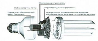
Fluorescent lamps do not work directly from a 220 volt network. They need a special adapter that will stabilize the voltage and smooth out the current ripple. This device is called ballast equipment (ballast), consisting of a choke, which smoothes out ripple, a starter, used as a starter, and a capacitor to stabilize the voltage. True, the ballast in this form is an old unit that is gradually being phased out. The thing is that it was replaced by a new model - electronic ballasts, that is, the same ballast, only of the electronic type. So, let's look at electronic ballasts - what it is, its circuit and main components.
What is electronic ballast
Electronic ballasts are electronic ballasts that can significantly extend the service life of lighting devices and make their operation more efficient. The component represents a module with contacts to which the input voltage terminals are connected, as well as a load in the form of lamps.
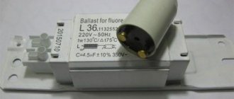
This is what the electronic ballast looks like.
The electronic ballast unit has become an effective replacement for obsolete stabilizers using chokes and starters. It is the electronic module that is installed in all modern devices.
Cost indicators
Cost indicators for electronic ballasts may be underestimated if the reliability, functionality and strength properties of materials decrease. Consequences:
- reduced service life, half the normal service life of similar parts;
- each start further reduces the specified service time;
- There may be no function for automatically adjusting output powers during network voltage fluctuations. While standard models are conditioned in operating voltage fluctuations up to 200 to 250 watts with a uniform luminous flux;
- Some models do not have automatic power off;
- Some electronic ballasts with a reduced price can only be supplied with alternating current.
Advantages and disadvantages
Considering the electronic ballast, we can highlight some features. There are both advantages that distinguish the block from competitors, and disadvantages.
Pros:
- The use of electronic ballasts in connection circuits for fluorescent lamps significantly extends the service life of the elements.
- High efficiency, losses during operation are minimized due to the elimination of the throttle.
- Energy saving.
- There are no surges or interference in the power supply or connected equipment.
- The lighting device operates stably without pulsation.
- If the lamp malfunctions, the system immediately stops supplying voltage to the contacts.
- The electrodes heat up smoothly, without sudden jumps or temperature changes.
- Even serious voltage drops in the supply network do not affect the stability of the luminous flux.
- Some models can operate on direct current.
- Reliable protection against short circuit or breakdown is provided.
- During operation, the circuit does not produce any extraneous sounds.
- With the help of electronic ballasts, you can start the lighting device even at low temperatures.
Connection to a fluorescent lamp.
There were some downsides:
- There are many cheap, low-quality devices on sale with a short service life.
- Good models are expensive.
- A significant part of the models cannot be used with LED lamps.
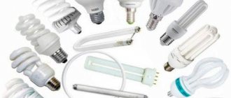
Kinds
Today, the following types of ballast devices are widely represented on the market:
- electromagnetic;
- electronic;
- ballasts for compact lamps.
The presented categories are marked by reliable operation and ensure long-term operation and ease of operation of all fluorescent lamps. All of these devices have identical operating principles, but differ in some respects.
Electromagnetic
These ballasts are suitable for lamps connected to the mains using a starter. The initially occurring discharge intensively heats up and short-circuits the bimetallic electrode elements. There is a sharp increase in operating current.
Electromagnetic ballast is easy to recognize by its appearance. The design is more massive compared to the electronic prototype.
When the starter fails, a false start occurs in the electromagnetic ballast circuit. When power is supplied, the lamp begins to blink, subsequently there is a smooth supply of electricity. This feature significantly reduces the working life of the lighting source.
| pros | Minuses |
| High-quality level of reliability, proven by practice and time. | Long startup - at the first stage of operation, startup takes 2-3 seconds and up to 8 seconds by the end of the service life. |
| Simplicity of design. | Increased energy consumption. |
| Ease of use of the module. | Lamp flicker at 50 Hz (strobe effect). It has a negative effect on a person who stays in a room with this type of lighting for a long time. |
| Affordable price for consumers. | The hum of the throttle is heard. |
| Number of manufacturing companies. | Significant weight of the structure and bulkiness. |
Electronic
Today, magnetic and electronic ballasts are used, which consist in the first case of a microcircuit, transistors, dinistors and diodes, and in the second case of metal plates and copper wire. By means of a starter, the lamps are started, and the phenomenon is organized in the electronic version of the part as a single function of this element with the ballast in one circuit.
- light weight and compactness;
- smooth fast start;
- unlike electromagnetic structures that require a 50 Hz network to operate, high-frequency magnetic analogues operate without noise from vibration and flicker;
- heating losses are reduced;
- power factors in electronic circuits reach 0.95;
- Extended service life and safety of use are ensured by several types of protection.
| Advantages | Flaws |
| Automatic ballast adjustment for different types of lamps. | Higher cost compared to electromagnetic models. |
| Instant switching on of the lighting device, without additional load on the device. | |
| Saving energy consumption up to 30%. | |
| Heating of the electronic module is excluded. | |
| Smooth light output and absence of noise effects during the lighting process. | |
| Increasing the service life of fluorescent lamps. | |
| Additional protection guarantees an increase in fire safety. | |
| Reducing risks during operation. | |
| An even supply of light flux eliminates rapid fatigue. | |
| Absence of negative functions in low temperature conditions. | |
| Compact and lightweight design. |
For compact fluorescent lamps
Compact types of fluorescent lamps are represented by devices similar to incandescent lamps of types E27, E40 and E14. In such schemes, electronic ballasts are built inside the cartridge. In this design, repairs in case of breakdown are excluded. It will be cheaper and more practical to purchase a new lamp.
Design and principle of operation of electronic ballasts
Any electronic ballast consists of the following elements:
- device for current rectification;
- electromagnetic radiation filter;
- circuit power factor correction unit;
- voltage smoothing filter;
- inverter;
- choke or ballast for lamps.
The structure can be pavement or half-bridge. The first option has improved characteristics and is used in high-power lamps, from 100 W. The circuit effectively maintains the glow indicators and the voltage supplied to the cathodes.
Disassembled electronic ballast.
Half-bridge circuits are more popular because Suitable for most household fluorescent lamps up to 50 W. Designs marked 2x36 support the connection of two 36 V lamps.
The operation of the device consists of the following steps:
- Turning on and preheating the filaments. This is an important manipulation that significantly extends the life of lighting sources. Without preheating, the lamp will not turn on at low temperatures.
- Generation of a high-voltage impedance pulse with a voltage of about 1.5 kV, which causes a breakdown of the gaseous medium inside the flask and starts the glow.
- Stabilize voltage and maintain it at the required level. The voltage to support combustion is low, which makes the circuit safe.
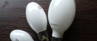
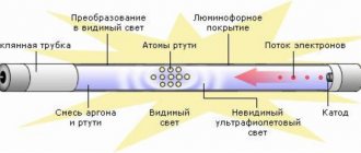
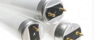
Fluorescent lamp device
A fluorescent lamp belongs to the category of classic low-pressure discharge lighting sources. The glass bulb of such a lamp always has a cylindrical shape, and the outer diameter can be 1.2 cm, 1.6 cm, 2.6 cm or 3.8 cm.
The cylindrical body is most often straight or U-curved. Legs with electrodes made of tungsten are hermetically soldered to the end ends of the glass flask.
Light bulb device
The outer side of the electrodes is soldered to the base pins. The entire air mass is carefully pumped out of the flask through a special rod located in one of the legs with electrodes, after which the free space is filled with inert gas with mercury vapor.
On some types of electrodes, it is mandatory to apply special activating substances, represented by barium oxides, strontium and calcium, as well as a small amount of thorium.
Connection diagram
Electronic ballasts have become an effective replacement for traditional circuits with chokes and starters, reducing the design of the luminaire and expanding its capabilities.
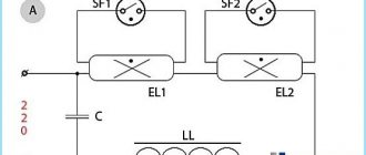
Connection diagram of one lamp to electronic ballasts.
Electronic ballasts do not have all the disadvantages of chokes. More than one lamp can be connected to one electronic ballast, and to some models up to four, without additional elements. The design works with standard lighting sources with a power of 18W, 36W, etc.
Connection diagram of several lamps to electronic ballasts.
It is better to place the block on the phase wire. If zero is present, the potential is maintained, which is expressed by slight flickering of the light source when the power is turned off. The phenomenon is typical for cheap ballasts.
To smooth out flicker, the capacitor is shunted with a resistor with a resistance of 100 kOhm.
How to connect EMPA
A few words about the design features of the electronic ballast. An electromagnetic ballast consists of at least an inductive ballast and an IZU pulse ignition device. The inductive ballast serves to accumulate electromotive force (EMF) before starting the lamp. The IZU directly provides the process of starting the lamp. If the kit includes a compensating capacitor, the efficiency of the electronic ballast increases. The capacitor shifts and smooths out peak values of power consumption, compensates for reactive power (it is not spent on performing useful work and is actually wasted). That is, using a capacitor increases the power factor of the lamp.
Safety, scope and launch types
This also creates the potential danger that when replacing a light bulb, you or an electrician may receive a shock if you even accidentally touch the lamp base, the metal case (if there is a leak), and so on.
In a similar situation, the electronic ballast will operate automatically, and the supply of electricity to the faulty circuit elements will be automatically blocked. This is what safety is all about.
Another distinctive feature and advantage of EmPR is that it can be connected to a direct current source, that is, from a battery. Therefore, it is widely used in security systems and emergency lighting. That is, the scope of application of electronic devices is much wider, and they are used even at important facilities of the 1st category of power supply.
According to the starting principle, electronic ballasts are divided into cold and warm starts. A warm start device first sends a signal to the lamp electrodes to warm up. When the temperature required for starting is reached, it lights up. The entire process takes milliseconds. Warm start devices last 3-4 times longer. Therefore, when choosing, it would also be nice to remember and take this into account.
Main functions
It is not possible to connect fluorescent light sources directly to the electrical network. There are the following reasons for this:
- to create a persistent discharge in a fluorescent lamp, it is necessary to preheat its electrodes and apply a starting pulse to them;
- Since gas-discharge light sources have a negative differential resistance, they are characterized by an increase in current strength after entering the operating mode. It must be limited to prevent the light source from failing.
Based on the reasons described above, it is necessary to use ballasts.
Electromagnetic type ballasts
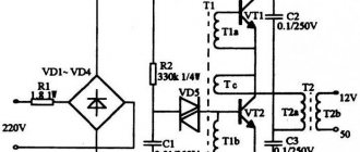
Electronic ballast power supply - diagram
Imported transistors MJE13003, MJE13007, and in rare cases MJE13009 and their analogues are used as power switches. Transistors can be said to be created specifically for operation in network UPSs. Similar transistors are used in computer power supplies. So, first I want to present the main advantages of such a power supply.
- Compact size and light weight
- Low costs and low cost
- Reliability of operation
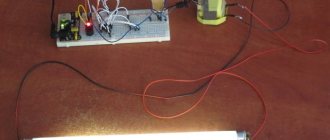
These are just the main advantages of our homemade block, but it also has other (hidden) advantages. Some UPSs only work under a certain load, in other words, the power supply will not be able to work when idle or with a low-power load. Quite popular ETs (electronic transformers), which are designed to power halogen lamps with a power of 12 volts, have this property. Our power supply turns on when mains voltage is applied and is capable of powering loads with power from fractions of a watt (LEDs, etc.) to 40-50 watts. Such a unit can be used as a laboratory power supply for a novice radio amateur.
The power supply is not afraid of short circuits at the output (instead, the electronic transformer fails after a second short circuit), has high operational stability and can operate for a very long time without turning off. The essence of reworking the ballast is to refine it. We need to wind a pulse transformer, which provides galvanic isolation from the 220 volt network and lowers the voltage to the level we need.
The transformer can be wound on almost any ferrite core (rings, armor cups or W-shaped core). The network winding contains 130 turns of wire 0.3-0.6 mm, the step-down winding should contain 8-9 turns, which corresponds to an output voltage of 12 Volts.
The voltage from the ballast is supplied to the transformer winding through a capacitor (select the capacitor voltage in the range of 1000-3000 volts, capacity 3300-6600 pF). It is advisable to wind the secondary winding of the transformer with several strands of thin wire (4 strands of 0.5 mm wire), the output is about 3.5-4 Amperes. It is also possible to use ready-made transformers from ET with a power of 50-150 watts.
To rectify the voltage, you should use powerful pulse diodes or diode assemblies from computer power supplies. From the domestic interior you can use KD213. When selecting diodes for a power supply from electronic ballasts, make sure that the maximum permissible current of the diode is in the region of 8-12 Amps; the diode itself should operate at frequencies of 100-150 kHz.
Very often, the cause of breakdown of an electrical appliance is a faulty battery. As a result, repairs or the purchase of new equipment are required. But you can avoid high costs by making a power supply from an energy-saving lamp yourself. All the necessary parts can be taken from a regular fluorescent lamp, the cost of which is low.
What is electronic ballast 4x18 (electronic starting device)
Ballast in circuits is used to limit the amount of current. At the moment a charge appears in the lamp gas, its value increases instantly, and the resistance drops. This causes the lamp contacts to heat up and possibly burn out. To prevent this, these devices are used.
Electronic starter for fluorescent lamps 4x18
For your information! The most widely used are electronic and electromagnetic ballasts. The electromagnetic module creates an adjustable inductive reactance of the coil. The electronic device modifies and regulates the signal itself.
Electromagnetic ballast
An electronic starter for fluorescent light bulbs has several advantages:
- prevents flicker;
- much smaller in size and weight;
- does not create extraneous noise;
- has a “hot start” mode, in which the lamp contacts are preheated, which increases their service life.
Electronic module device
How to choose a driver for an LED lamp?
Voltage stabilizers for LED lamps are sold complete with the device itself and are manufactured for a specific model, but if necessary they can be purchased separately. Electronic ballasts constantly experience power fluctuations, so they usually wear out earlier than the LED element of the lamp, and sooner or later it will need to be replaced. The most commonly used are stabilizers for 36w and 40w lamps with a current of 350 or 700A.
While doing its job (converting alternating current to direct current), electronic ballasts consume a certain amount of electricity - approximately 20% of the lamp power. Therefore, when choosing a device, you need to multiply the lamp power by a factor of 1.2 - this will be the optimal driver power for this model. If the power and the LED do not match, their operation will be incorrect, the electronic ballast may overheat and quickly fail, or the LED will deteriorate.
The voltage stabilizer can be placed either inside the lamp (in a specially designated area of the housing) or separately. When placed inside the case, it is important to select the correct size driver.
Source: lt-electro.ru
How to make a lamp with your own hands?
You can make a simple lamp from two lamps as follows:
- select 36 W lamps that are suitable for color temperature (shade of white);
- We make the body from a material that will not ignite. You can use the housing from an old lamp. We select electronic ballasts for a given power. The marking should indicate 2 x 36;
- We select 4 sockets marked G13 for the lamps (the gap between the electrodes is 13 mm), a mounting wire and self-tapping screws;
- cartridges must be secured to the body;
- The installation location of the electronic ballasts is chosen to minimize heating from operating lamps;
- the cartridges are connected to the LDS sockets;
- to protect lamps from mechanical stress, it is advisable to install a transparent or matte protective cap;
- The lamp is fixed to the ceiling and connected to a 220 V power supply.
The simplest lamp of two lamps
Efficient synchronous rectifier. Or a second life for electronic junk
Current rectification using a diode and transistor: advantages and disadvantages.
We will talk about a rectifier circuit using insulated gate transistors, English. Abbreviated as Mosfet.
The circuit uses the most common Mosfet with an induced N-conductivity channel. The main advantage due to which such switches are widely used in modern electronic devices in power circuits is their low resistance and voltage drop in the open state (no more than 0.1 V).
Here is a classic connection diagram for checking and studying the operation of a transistor with an N-channel:
Connection circuit for checking the Mosfet transistor
The opening of a switch with an N-channel occurs when a positive voltage is applied (charge the gate) to the gate (Gate) relative to the source (Source), respectively, in order to close the transistor, you need to discharge the gate, that is, the potential on it must be lower than the junction opening voltage. When open, the key conducts current in both directions.
Let me remind you that the circuit of such a transistor and the pinout are as follows:
There are features that need to be taken into account when rectifying current using such a transistor:
- presence of a parasitic diode between drain and source.
- The gate has a capacitance, which affects the response speed as the frequency increases.
The question arises: what is the efficiency of the rectifier on these transistors and why all these difficulties? Schottky diodes have long been invented, the direct drop at the metal-semiconductor junction of which is two times less than at the PN junction of a conventional silicon diode, but when low-voltage power supply and high current consumption are needed, the efficiency losses even on Schottky diodes are already significant!
Table of power losses on Schottky diodes when operating at different voltages:
| power supply voltage | drop on a Schottky rectifier diode | power dissipated by diode | losses |
| 12 V* 1 A=12 Watt | 0.4V 1A | 0.4 Watt | 4,8 % |
| 5 V* 2 A=10 Watt | 0.4 V 2 A | 0.8 Watt | 8 % |
| 3.1 V* 3 A=9.3 Watt | 0.4 V 3 A | 1.2 Watt | 11% |
In modern computer technology, where processor supply voltages can be within 1 V, the power supply of the entire computer is made at a higher voltage, while the efficiency does not suffer due to losses on the rectifier, and already in the circuit itself the voltage of the power supply is converted by pulsed step-down converters with using synchronous rectifier circuits based on Mosfet.
Below is a famous power supply circuit with low output voltage and using Mosfet as a rectifier.
Low Output Voltage Rectifier Using Mosfet Transistor
The upper winding of the transformer is the control winding of the transistor, the lower one is the power winding, the number of its turns determines the output voltage of such a rectifier, and the cross-sectional area determines the current. We'll look at the details below.
Second life of CFL electronic ballasts
Radio amateurs have long been widely using burnt-out “housekeeper” (CFL) boards with an electronic ballast circuit, as well as electronic transformers similar in design to power halogen lamps in their projects. Now this is relevant due to the transition to more efficient LED lighting; such electronic transformers and ballasts are no longer needed, and they can be used as a power source for other purposes after a simple modification.
The electronic ballast of energy-saving lamps can be repaired; there is an article about this: Repair of energy-saving lamps.
In the circuit of a standard CFL ballast, the modification consists of installing a jumper as shown in the diagram:
Types of ballast
Different types of ballasts are grouped by implementation type: electronic and electromagnetic implementation. In addition, the models are classified according to the area of application for lighting devices, among which are:
- High frequency electronic ballast for fluorescent luminaires, with or without preheating. The first model increases the performance and service life of the device, and also reduces the noise effect. Ballast without preheating consumes less energy. High frequency ballast for sodium lamps. This is a less bulky ballast than conventional models installed on low-pressure lamps, easy to install, and with low energy consumption for its own needs.
- Electronic ballast for gas discharge devices. This model is usually designed for high pressure sodium and metal lamps, increasing their lifespan by up to 20% compared to the standard. The start-up time is reduced, as are the flashing effects. It should be noted that these ballasts are not suitable for all luminaires.
- Multi-lamp ballast. It has the advantage that it can be used with several types of fluorescent devices, including aquarium lighting, creating an optimal primer. It has the function of recording all lighting parameters in its memory.
- Digitally controlled ballast. This is the latest generation model, offering a lot of flexibility and modularity when installing luminaires. This improves the economic aspect of the LED lamp and the brightness comfort. At the same time, it is the most expensive model.
Electromagnetic implementation
Magnetic ballasts (MB) are devices with old technology. They are used for the fluorescent lamp family and some metal halide devices. They tend to cause humming and flickering because they regulate current gradually. MBs use transformers to convert and control electrical power. When the current arcs through the light fixture, it ionizes a larger percentage of the gas molecules. The more of them are ionized, the lower the gas resistance. Thus, without MB, the current will rise so high that the lamp will heat up and destroy.
Electromagnetic implementationThe transformer, which in MB is called a “choke”, is a wire coil - an inductor that creates a magnetic field. The more current flows, the greater the magnetic field, the more the current growth slows down. Because the process takes place in an alternating current environment, the current flows in one direction for only 1/60 or 1/50 of a second and then drops to zero before flowing in the opposite direction. Therefore, the transformer only needs to slow down the flow of current momentarily.
Electronic implementation
The performance of electronic ballasts is measured using various parameters. The most important is the ballast factor. This is the ratio of the luminous output of a lamp, controlled by the EB in question, to the luminous output of the same device, controlled by a reference ballast. This value ranges from 0.73 to 1.50 for EB. The significance of this wide range lies in the levels of light output that can be achieved using a single EB. This finds great use in dimming circuits. However, it has been found that too high and too low ballast factors degrade luminaire life due to lumen wear resulting from high and low current, respectively.
You might be interested in: Features of connecting IZU for DNAT
Electronic implementation
When EBs are to be compared within the same model and manufacturer, the ballast efficiency ratio is often used, which is the ratio of the ballast ratio expressed as a percentage to power and provides a relative measurement of the system efficiency of the entire combination. A measure of the efficiency of a ballast, power factor (PF) is a measure of the efficiency with which the EB converts supply voltage and current into usable power supplied to the lamp with an ideal value of 1.
Conclusions and useful video on the topic
The video material, based on the practice of an electrician, tells and shows which of the two devices should be recognized by the end user as better and more practical.
This story once again confirms that simple solutions look reliable and durable:
Meanwhile, electronic ballasts continue to be improved. New models of such devices periodically appear on the market. Electronic designs are also not without drawbacks, but compared to electromagnetic options, they clearly show better technical and operational qualities.
Do you understand the principles of operation and connection diagrams of electronic ballasts and want to supplement the above material with personal observations? Or would you like to share useful recommendations on the nuances of repairing, replacing or choosing a ballast? Please write your comments on this entry in the block below.