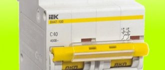
Circuit breakers are designed to protect wiring and equipment from overcurrents created by short circuits. They are used everywhere, both to protect household appliances and ensure the safety and safe operation of industrial equipment. However, there is a special type of device that becomes the first obstacle on the way from the substation to the facility. This is a two-pole circuit breaker, or a so-called two-pole circuit breaker.
How to choose a two-terminal network?
In order for a circuit breaker to fully provide the necessary protection, it is necessary to carefully select it.
The main thing is not to make a mistake with the denomination. To do this, you need to know the rated load that you plan to connect to the device. The current in the circuit protected by the circuit breaker is calculated using the formula: I = P / U, where P is the rated load, and U is the network voltage.
For example: if a 400 W refrigerator, a 1500 W electric kettle and two 100 W light bulbs are connected to the device, then P = 400 W + 1500 W + 2 × 100 = 2100 W. At a voltage of 220 V, the maximum current in the circuit will be equal to: I = 2100/220 = 9.55 A. The rating of the machine closest to this current is 10 A. But in the calculations, we have not yet taken into account the wiring resistance, which depends on the type of wires and their cross-section. Therefore, we buy a switch with an operating current of 16 amperes.
We provide a table that helps determine the network power to be taken into account when calculating current strength.
| Current strength | 1 | 2 | 3 | 4 | 5 | 6 | 8 | 10 | 16 | 20 | 25 | 32 | 40 | 50 | 63 | 80 | 100 | |
| Single-phase network power | 02 | 04 | 07 | 09 | 1,1 | 1,3 | 1,7 | 2,2 | 3,5 | 4,4 | 5,5 | 7 | 8,8 | 11 | 13,9 | 17,6 | 22 | |
| Wire sizes | copper | 1 | 1 | 1 | 1 | 1 | 1 | 1,5 | 1,5 | 1,5 | 2,5 | 4 | 6 | 10 | 10 | 16 | 25 | 35 |
| aluminum | 2,5 | 2,5 | 2,5 | 2,5 | 2,5 | 2,5 | 2,5 | 2,5 | 2,5 | 4 | 6 | 10 | 16 | 16 | 25 | 35 | 50 |
Using the table, you can accurately calculate the necessary parameters of a two-pole circuit breaker.
As for the stores where you can buy them, focus on prices and product range. From the list of manufacturers we can recommend, for example, the Legrand brand.
Where and how to use a three-pole circuit breaker to protect equipment
The three-pole circuit breaker is not a new concept used to protect three single-phase loads to save space and cost.
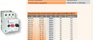
But what if the protected loads, for example electric motors, have different technical data and require different types of protection? In many applications - for example machines and installations with multiple loads - it usually makes sense to protect each load separately and individually.
Optimal electrical load safety
Individual protection, as opposed to group protection, ensures optimal safety for each electrical load from possible damage caused by overheating. In addition, the possibility of false positives is eliminated. If single-pole protection is sufficient, then such equipment protection circuit breakers can reliably cope with this task. Example: If three motors are to be protected in one unit, three single-pole circuit breakers will be required for this purpose.
Another alternative is to use three single-pole switches instead of one three-pole switch. This will significantly reduce installation time and space requirements. Additionally, in the event of a load failure, all three loads will always be disconnected from the supply voltage, including the faulty loads. This will ensure complete shutdown of the unit.
Three-pole circuit breaker and its features
However, a three-pole circuit breaker can only be used if the current ratings of the circuit breakers are matched to the operating characteristics of the loads. If the three loads to be protected are three identical electric motors, any standard three-pole circuit breaker can be used. But what if the motors you use require different switch ratings? Standard three-pole circuit breakers must be turned off because their three-pole chambers have the same ratings.
ETA thermal circuit breaker combinations such as the three-pole 3130 or the multi-pole push-button 3140 offer a potential solution. Their pole chambers can be equipped with various bimetallic releases. This allows users to select the required current values from the entire range of circuit breaker current values.
Types of Circuit Breakers
The 3130 three-pole rocker-operated circuit breaker can have 5 A bimetal in the first pole chamber, 10 A bimetal in the second chamber, and 16 A bimetal in the third chamber. The ETA 3130 and 3140 circuit breaker types have international approvals including VDE, UL, CSA and CCC, even though they are equipped with different bimetallic releases, and are therefore suitable for global use.
Multi-pole circuit breakers can be especially useful when used to protect single-phase or DC loads. If a multi-pole circuit breaker is intended to protect different loads, then the current ratings in the different pole chambers should be adjusted according to the load breaking limits. ETA circuit breaker combinations meet these requirements.
Is it possible to combine single-pole circuit breakers into two-pole or three-pole circuit breakers?!
Let's move on to connecting the circuit breaker
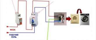
If there is voltage on your supply wire, it must be turned off before starting work. Then make sure there is no voltage on the connected wire using a voltage indicator. For connection we use VVGngP 3*2.5 three-core wire, with a cross-section of 2.5 mm.
We prepare suitable wires for connection. Our wire has double insulation, common outer and multi-colored inner. Let's decide on the connection colors:
- blue wire - always zero
- yellow with green stripe - earth
- the remaining color, in our case black, will be the phase
Phase and neutral are connected to the terminals of the machine, ground separately to the feed-through terminal. We remove the first layer of insulation, measure the required length, and bite off the excess. Remove the second layer of insulation from the phase and neutral wires, about 1 centimeter.
Unscrew the contact screws and insert the wires into the contacts of the machine. We connect the phase wire on the left, and the neutral wire on the right. Outgoing wires should be connected in the same way. After connecting, be sure to check again. Care must be taken to ensure that the wire insulation does not accidentally get into the clamping contact, as this will cause the copper core to have poor pressure to the machine contact, which will cause the wire to heat up, the contact to burn, and the result will be failure of the machine.
We inserted the wires, tightened the screws with a screwdriver, now you need to make sure that the wires are securely fixed in the contact clamp. We check each wire separately, swing it a little to the left, to the right, pull it up from the contact, if the wire remains motionless, the contact is good.
In our case, a three-wire wire is used; in addition to phase and zero, there is a grounding wire. In no case is it connected through a circuit breaker; a feed-through contact is provided for it. Inside, it is connected by a metal bus so that the wire passes without breaking to its final destination, usually sockets.
If you don’t have a feed-through contact at hand, you can simply twist the incoming and outgoing wires together using a regular twist, but in this case you need to pull it well with pliers. An example is shown in the picture.
The feed-through contact is installed as easily as a machine; it snaps onto the rail with a slight movement of the hand. We measure out the required amount of grounding wire, bite off the excess, remove the insulation (1 centimeter) and connect the wire to the contact.
Do not forget to make sure that the wire is well fixed in the contact clamp.
Suitable wires are connected.
If the circuit breaker trips, the voltage remains only on the upper contacts; this is completely safe and is provided for in the circuit breaker connection diagram. The lower contacts in this case will be completely disconnected from the electric current.
We connect the outgoing wires. By the way, these wires can go anywhere to a light, an outlet, or directly to equipment, for example, to an electric water heater or electric stove.
We remove the outer insulation and measure the amount of wire required for connection.
We remove the insulation from the copper conductors and connect the wires to the machine.
Prepare the ground wire. We measure out the required amount, clean it, connect it. We check the reliability of fixation in contact.
The connection of the circuit breaker has come to its logical conclusion, all wires are connected, and voltage can be applied. At the moment, the machine is in the down position (off), we can safely apply voltage to it and turn it on, to do this we move the lever to the up position (on).
By connecting the circuit breaker with our own hands, we saved:
- calling an electrician - 200 rubles
- installation and connection of a two-pole circuit breaker - 300 rubles
- DIN rail installation - 100 rubles
- installation and connection of a feed-through grounding contact 150 rubles
TOTAL: 750 rubles
*The cost of electrical installation services is shown in the pricing table
Difference between double-pole and single-pole circuit breaker
The difference between a single-pole and a double-pole switch is that the first monitors the technical parameters of several lines. Accordingly, the difference between two and three-pole is that in the first two lines are monitored, and in the second - three lines. When the voltage in one is exceeded, the device protects each line. The second device protects only one power line. At the same time, it is impossible to replace a two-pole circuit breaker with several single-pole ones due to the shutdown lever. The interlock is designed so that if there is a problem, both lines will be disconnected. In addition, the current will not evaporate. It will penetrate into a properly working device and a fire may occur.
Difference between double-pole and single-pole circuit breaker
Advantages and disadvantages
The advantages include reliable protection, the ability to control power, and ease of installation and maintenance. The main advantage is the de-energization of several conductors, regardless of the occurrence of an accident in any of them. Thanks to this, tension is completely removed.
You might be interested in: Installation of an electric meter
The disadvantages of a multi-pole protective device are the possibility of cable breakdown by electric current during a simultaneous short circuit of several electrical networks.
Note! They also include turning off the power to the electrical wiring during a breakdown of the thermal release, the inability to turn on the power after an emergency line breakdown and sensitivity to mechanical damage
Specifications
Technical characteristics of two-pole circuit breakers vary depending on price and manufacturer. The rated voltage is 240 watts, the rated current is from 6 to 63 amperes, the number of poles is from 1 to 4, the time-current characteristic is designated B, C and D.
Technical characteristics of electrical equipment
Installation and connection diagrams
A two-pole circuit breaker is installed according to the electrification plan. The housing is checked for damage and deformation before installation. The operation of the shutdown handle must be of high quality. During installation, the connection of a copper conductor using a lug and the connection of an aluminum cable using an end piece are taken into account. The upper group of stationary circuit breakers, conductor sealing with insulating tubes and protective tape, the distance of nodes and the location of the additional box are also taken into account.
The machine is placed on part of the DIN rail. The latch bracket is removed using a flat-head screwdriver and placed on the rail with fasteners. During installation, the usual scheme is used. An input switch is placed before the meter, after it a two-pole type device is mounted, and a neutral with a phase is connected on top. The cores are routed from below to the circuit. Wired copper jumpers are used to connect multiple devices together. The end is cleaned using a sharp object and crimped using a crimper.
Note! During installation of the device, work must be carried out by two specialists wearing protective rubber gloves after obtaining permission from the housing and communal services. The connection must be made to the panel without damage at the mounting location
How to choose based on device characteristics and functions
The main parameter by which a circuit breaker is selected is the total current load from all connected electrical appliances
You also need to pay attention to other factors - network voltage, number of poles, housing security, wire cross-section, condition of electrical wiring
Determining the polarity of the machine
Depending on the type of electrical wiring, the pole of the machine is selected. For single-phase networks, single- and two-terminal devices are used; for three-phase electrical networks, devices with three and four poles are used.
Current selection
Current is the most important characteristic influencing the choice of machine. It is this indicator that determines whether the protection will work in an emergency. For electrical panels located near electrical substations, a 6 kA protective device should be purchased. In residential premises this value increases to 10 kA.
Operating or rated current
Operating currents are determined by the total load of all household appliances that the machine protects. The cross-section of electrical wires and their material should also be taken into account.
For the lighting group, 10 Amp circuit breakers are usually used. Sockets can be connected to 16 Amps. Heavy-duty appliances like electric stoves and water heaters require 32 amps at the circuit breaker.
The exact value is calculated as the total power of all household appliances divided by 220 V.
It is undesirable to greatly increase the operating current - the machine may not work in an accident.
Short circuit current
To select a circuit breaker based on short circuit current, you should use the rules of the PUE. It is prohibited to use switches with a breaking capacity lower than 6 kA. In homes, 6 and 10 kA devices are most often used.
Selectivity
This term refers to the disconnection in an emergency of only the problematic section of the electrical network, and not all the energy in the house. You should select machines for each group of devices separately. The input circuit breaker is selected for 40 A, then devices with a lower current are installed for each type of household device.
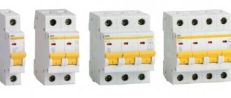
Number of poles
There are several types of machines: single-pole, two-pole, three-pole and four-pole. Single-terminal circuits are used in a single-phase network (one phase, two, three wires). The neutral is not protected in this case. Used for socket group or for lighting. A double pole switch is used for electrical wiring with one phase and two wires. Can be used as an input fuse for the entire network and to protect individual electrical appliances. Devices with two poles are the most common.
Replacing one two-terminal device with two single-terminal devices is prohibited by the rules of the Electrical Installation Code.
Three-terminal and four-terminal networks are used in a three-phase 380 Volt network. They are spilled by the presence of a neutral wire in a device with four poles.
Cable cross-section
The cross-section and material of the cables has a huge influence on the choice. Homes built before 2003 used aluminum wiring. It is weaker and needs replacement. It is impossible to install a new switch selected only by total power.
Copper cables carry higher currents than aluminum cables
Here it is important to take into account the cross-section - copper products with an area of 2.5 sq. mm. operate safely with currents up to 30 A
To determine the required value, use tables for calculating cable cross-section.
Manufacturer
You definitely need to pay attention to the manufacturer of the machine. It is better to purchase the device from a well-known, trusted company in a specialized store.
This will reduce the risk of buying a fake, and the purchased product will meet the stated criteria. Also, branded stores provide a guarantee on the switch.
Housing protection degree
Each switch has its own degree of housing protection. It is written as IP and 2 digits. Sometimes 2 Latin letters may be additionally used to describe auxiliary characteristics. The first number indicates the degree of protection from dust, the second – from moisture. The higher the number, the higher the security of the machine body.
Marking
The switch is marked with letters and numbers. It is deciphered as follows:
- letter A, B, C, etc. – class of the machine, means the instantaneous current limit;
- the number indicates the rated current at which the device operates in normal mode;
- A number in thousands of amperes is also indicated next to it, indicating the maximum current value at which the switch will respond.
The markings are indicated on the device body and in the relevant documentation.
Device structure
Usually it is installed in a single-phase 220 V network, and to protect electrical lines with three-phase voltage, three-pole and four-pole circuit breakers are used. Important protection elements in a 2-pole circuit breaker are:
- electromagnetic mechanism;
- thermal release.
Electromagnetic protection mechanism
The design elements of this protection are triggered when a short circuit occurs in one of the lines. At the same time, large currents arise in the circuit, which can exceed the permissible value by several thousand times.
The solenoid is located inside a spring that connects the thermal release in series with the power contacts. The operating current is too small for the magnetic flux to pull in the core.
When the current increases sharply, the coil retracts the solenoid, compressing the spring, and it disconnects the contacts. In the normal state, the spring expands and the contacts are connected again.
Thermal release
A distinctive feature of this protective mechanism is that it operates much more slowly than the electromagnetic one. It is able to withstand the maximum load for some time, and if it does not drop to the operating value, it will disconnect the contacts. By the way, this mechanism does not react in any way to a short-term change in current strength.
The design of the release includes:
- bimetallic plate;
- release mechanism lever;
- contacts.
On what principle does a single-pole circuit breaker work?
Circuit breakers, like switching devices, perform the functions of conducting permissible electric current and turning off the power if the rating is exceeded, thereby protecting the electrical network from overload.
The task of a single-pole device is to protect the circuit in one wire. The operation of the device is concentrated on 2 distribution devices - thermal and electromagnetic. When the increased load lasts for a long time, the circuit is disconnected by the first mechanism. If a short circuit occurs, the second distributor immediately stops supplying power.
Thermal protection is performed by a plate made of composite material according to the following principle:
- A current exceeding the permissible level is supplied.
- The bimetal heats up.
- Bends.
- Pushes the lever.
- Turns off the device.
- The plate cools down.
When the condition of the bimetal returns to normal, it returns to its original state and the device can be reconnected. The electromagnetic device includes a coil in the middle of which a core is placed.
Here's the picture:
- A short-circuit current occurs.
- Enters the winding.
- The force created by the electromagnetic field moves the core.
- Disables the device.
During the interaction of physical processes, power contacts are opened, which de-energize the conductor.
A high current intensity creates an electric arc; it is directed into a chamber with parallel metal plates for crushing and complete disintegration. The machine can be turned off by simply turning the knob. Such switches are used in ordinary apartments if only 2 wires are connected to the house. In a barn or small private house, single-pole circuit breakers open the circuit. In apartment buildings there are grounding conductors, which means only a two-terminal network will do.
This is interesting: Is it necessary to insulate a chimney made from a sandwich pipe in a metal profile box: let’s look at the essence
General properties of switches
Regardless of how many poles there are in the switch, they perform one task - they protect the electrical network from short circuits in an emergency . Even 2 devices structurally combined in one box operate on the same principle.
A circuit break occurs when the rated current is exceeded. Power can be turned off if the circuit is overloaded or there is a risk of a short circuit. The heat distributor immediately sets the contact in motion, which blocks the flow of current. The devices have replaced fuses, while remaining compact, easy to operate, but significantly superior in reliability to their outdated counterpart.
Areas of application
3-phase circuit breakers are used wherever there is a three-phase power supply. Connecting consumers without these protective devices is a gross violation of the rules for electrical installations. It is pointless to list all examples of the use of three-phase machines. Too many of them. Therefore, below are electrical devices that are protected by three-phase circuit breakers, but to some extent are found in the life of every person:
- street lighting networks;
- three-phase asynchronous motors of elevator equipment;
- input distribution devices of residential buildings;
- protection of engines of children's attractions;
- engines of pumping stations that pump water to residential buildings;
- pumps pumping out sewage water are protected by three-phase circuit breakers.
Three-pole circuit breakers are used everywhere. Their use is mandatory wherever there is a 3-phase power supply. Three-pole protection devices are almost no different from single-pole ones. The differences lie only in the number of protected phases, maximum operating currents and overall dimensions.
When connecting a three-terminal network, it is necessary to take into account its timing characteristics and rated current. These parameters are indicated on the body of the protective device
You should also pay attention to the series of the machine. It is determined based on the conditions of future operation, that is, how often the device will be triggered by a short circuit, how many times a day it will be switched by hand
Automatic machines for three-phase networks
Three-phase input provides some advantages compared to single-phase. This is the ability to use powerful energy consumers and ease of connection of electric motors
Using such a network, it is important to evenly distribute the load between all three phases to avoid voltage sags. It is advisable to use a four-pole input circuit breaker, and protect the outgoing lines with single-pole and three-pole circuit breakers
When choosing three-pole circuit breakers to protect equipment with electric motors, pay attention to the overload capacity of the machine. To avoid false alarms of the protective device, use machines with characteristic “D”
Device characteristics
The design of the two-pole device is made taking into account the observation and comparison of the functioning of two electrical circuits. They are usually installed in a single electrical line to control its two sections. There are 2 types of these devices available:
- With one pole blocking and standard neutral wire connection.
- With protection of both lines and their simultaneous switching.
The first type is installed at the entrance to the electrical main, and it controls the functioning of the phase and neutral conductors. In addition, it is possible to use a grounding wire with this device. The second type operates in circuits of one circuit and controls the operation of two sections under different current loads.
Classification of electrical machines
There are several typical circuit breaker shutdown characteristics: A, B, C, D, E, K, L, Z
- A
– for breaking long-distance circuits and protecting electronic devices. - B
- for lighting networks. - C
- for lighting networks and electrical installations with moderate currents (current overload capacity is twice that of B). - D
– for circuits with inductive loads and electric motors. - K
– for inductive loads. - Z
– for electronic devices.
Machine characteristics
Cutaway circuit breaker
Essentially, this is a triple version of a single-pole device for an electrical circuit with three phases. The design feature is the presence of protective functions on each individual pole. The main characteristics are the permissible short-circuit current at which the circuit breaker trips and the cut-off speed.
There are two mechanisms for shutdown - electromagnetic and thermal. In the event of a short circuit, the electromagnet opens the circuit. Thermal is triggered by prolonged load exceeding the rated load. The device is also a switching device. If necessary, the machine can be used to turn the current on or off.
By design, the device has the following elements:
- control mechanism;
- power contacts;
- electric arc extinguishing unit;
- release;
- pole terminals for connecting wires.
What if you choose the wrong machine denomination?
The main mistakes that are made when you need to choose a machine based on load power are: choosing a rating that is too high or, conversely, a current rating that is too small.
If you choose a device with a low rating, the circuit breaker will constantly turn off when electrical appliances are operating, lighting will disappear and important mechanisms will stop working. In this case, the laid cable will have a power reserve, but the circuit breaker will not allow a current higher than its rating to pass through it (which will be less than the rating of the cable).
In the second case, if you choose the wrong machine, with a “reserve” of power, you will expose yourself to the risk of fire in the electrical wiring. Since the power for which the cable line is designed will be significantly lower than the capacity of the circuit breaker and it simply will not work, since the electric cable will already melt, and the circuit breaker will still have a reserve of work.
Plus, the higher the nominal value of the machine, the more expensive it is. If you make such a mistake, you will overpay and expose yourself to significant risk, the operation of the electrical system will be ineffective and unsafe.
Very often a problem arises that the machine turns off or does not work correctly, but its nominal value is selected correctly. This happens because the device class, which is associated with the characteristics of the release, is incorrectly selected.
Buying tips
When purchasing, it is important to purchase equipment that can ensure safety. Single- and two-pole AVs are used in single-phase networks, and devices with a large number of poles are used in three-phase networks. Single- and two-pole AVs are used in single-phase networks, and devices with a large number of poles are used in three-phase networks.
Single- and two-pole AVs are used in single-phase networks, and devices with a large number of poles are used in three-phase networks.
Marking
At first glance, it is not easy to understand the AB markings. Manufacturers often indicate the serial numbers of their products in the name. Sometimes information is “scattered” on the front side, but the parameters necessary for the correct choice are necessarily present.
Having AB in front of you, it is easier to consider the quantities of interest:
- The rated voltage must correspond to the parameters of the electrical network. In a single-phase circuit there is an alternating voltage of 220 V with a frequency of 50 Hz.
- The time-current characteristic indicates the permissible limits for exceeding the rated current required for the protection to operate. Designated by the letters A, B, C, D, Z, K. For an apartment, automatic switches for lighting are chosen - with the letter B, for sockets - C, for powerful motors and transformers - D. Series A devices are too sensitive and are designed to protect circuits with increased requirements. You will have to turn on the load after small voltage fluctuations in the network. K and Z – devices for production needs.
- The rated current is indicated in amperes, and the AV is capable of passing this amount continuously without heating up or turning off.
- The current-breaking capacity of the machine (maximum shutdown current) shows the permissible current, after which the device will remain operational. Huge short-term loads are possible during a short circuit. For AV installed in an apartment (house), choose 4500 or 6000 A.
- The current limiting class indicates the “speed” of operation of the machine. There are 3 classes. The first class of devices is not indicated on the front panel, and the response time is more than 10 ms, the second class of devices turns off the load in a time of 6 to 10 ms, the third, the fastest, de-energizes the network in 2.5-6 ms.
- The electrical circuit of the device, indicated on AB, is described below.
Power
There are two methods of calculation when choosing AB:
- The maximum currents flowing through all electrical appliances connected through one circuit breaker are summed up. Having provided a margin of 15-20%, select a device protected by rated current.
- Compare the total power of all devices and the rated power of the AV, choosing “protection with a margin” of 10-15%.
It is important to understand that AVs can withstand currents exceeding the rated current by 40% for approximately an hour of operation. During this period of time, excessive heating of the wiring may occur, melting and, ultimately, a short circuit.
| Rated current AB, A | Current in single-phase network, A | Estimated load power, kW | Required core cross-section, mm2 |
| 16 | 0-15 | 3,0 | 1,5 |
| 25 | 15-24 | 5,0 | 2,5 |
| 32 | 24-31 | 6,5 | 4,0 |
| 40 | 33-40 | 8,0 | 6,0 |
| 50 | 40-49 | 9,5 | 10,0 |
Manufacturer and price
Automatic single-pole switches are present in the line of all manufacturers of electrical products. It is worth understanding that a European or American brand does not indicate the place where the plant is located. There is a high risk of finding a fake on sale. The table contains manufacturers and average prices for the popular 25-amp circuit breaker. Companies are sorted in order of decreasing user popularity (based on reviews on forums and review sites). Prices are taken from Yandex Market.
| Manufacturer | Average price, rub. |
| ABB | 180-400 |
| Legrand | 140-190 |
| Schneider Electric | 160-320 |
| General Electric | 200-350 |
| Siemens | 190-350 |
| Moeller | 160-290 |
| DEKraft | 80-140 |
| IEK | 100-150 |
| TDM | 90-120 |
Basic mistakes when buying
- You cannot install an AV that can withstand more current than the one for which the wiring is designed.
- The rating of the machine must take into account the power of the devices connected to the line.
- It is necessary to choose products from trusted companies, asking the seller for a product certificate.
- For individual sections of the circuit, where powerful consumers can be connected (welding, heater), separate wiring is laid and an automatic machine is installed.
Marking of a difavtomat: what do the icons on the case mean?
The differential automatic machine is produced in two types of modules for operation in:
- two-phase household wiring of an ordinary apartment;
- or three-phase, used in a private home.
For the first case, the difavtomat is made of a two-pole module with a phase wire input connected to its terminal “1” and its output from “2”. The working zero is connected to the “N” terminals.
On certain types of structures, the terminals at the top may be designated 1/2, and at the bottom 2/1. This means that the input and output of the phase conductor can be connected from either side.
On the left in the picture I showed the device of the difavtomat, and on the right - the designation on the diagrams that are used when drawing them in a simplified single-line version and a more detailed two-line version for a household network with a voltage of 220 volts.
The differential switch for a three-phase 380 volt network is shown in a similar way. Its design accommodates four poles.
The first three sockets on the left and top, marked “1”, “3”, “5”, are supplied with the corresponding phase circuits. They are also removed from sockets “2”, “4”, “6”. To connect the zero on the right, the “N” terminals are used.
The installation of all four manual control levers is mechanically linked. Switching occurs simultaneously, which is a prerequisite for eliminating the partial-phase power supply of consumers.
As you can see, the neutral (neutral wire) is always connected to the rightmost pole .
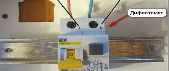
The design of the difavtomat and the layout of its mechanisms is shown in the figure below. Structurally, it consists of a pair of built-in blocks: on the left is a circuit breaker, on the right is an RCD.
The four-pole device is designed in the same way. It has three left blocks - automatic switches, the right one - a differential organ.
A control lever with an input and release mechanism allows you to manually switch the electrical circuit with power contacts.
The “Test” button is intended to test the functionality of the residual current device mechanism. When it is pressed, a leakage channel is artificially created corresponding to the RCD setting and the removal of power from the power contacts is checked.
When huge short-circuit currents break, the contacts of the electromagnetic release break an arc with high temperature and energy. It reaches behind the moving contact, creating a high-pressure zone from the smoke and combustion products of the surrounding air.
All this is sent into the atmosphere through the labyrinths of the arc-extinguishing chamber, where the arc stretches and fades.
It is important to understand: reliable elimination of short-circuit currents is ensured only by the joint operation of the electromagnetic cut-off with the arc extinguishing chamber.
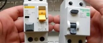
Structurally, the residual current device and the differential circuit breaker are very similar. They are manufactured in modules of the same type, which are easy to confuse for an inexperienced user.
When the question arises of how to distinguish a difavtomat from an RCD, then immediately look at the designation of electromagnetic and thermal releases.
They are absent in the design of the RCD.
Elite models of difavtomats have an operation indication, by which one can judge the reason for the shutdown: there has been a leak through the insulation or an overload, a short circuit. This option is not available on budget products.
Installing such an indicator speeds up the search and detection of faults, repairs, and commissioning of electrical wiring after the emergency has been eliminated. The benefits are obvious.
When selecting a differential switch for your home, pay attention to the technical data marked by the manufacturer on its body.
Let's look at it in a little more detail.
Rated current: the most important parameter for selecting and connecting a difavtomat
For domestic purposes, devices are used that operate with a load normalized by currents of 6, 10, 16, 20, 25, 32, 40, 50, 63 amperes. These basic values of the household network are determined by the standard series according to GOST 6827-76.
Diphavtomats, up to 16A, are installed for lighting systems, 40 A and above - at the input. Intermediate ratings are selected for socket groups and individual powerful consumers.
The rated current limits the loads that can flow unhindered in the protected circuit. Anything above this value will simply be disabled.
On the other hand, when choosing, you should bring the sensitivity of the machine as close as possible to the rated current to the critical loads that consumers and cables and wiring can withstand.
Coarsening can lead to wires burning due to overload, and the protection will not even feel it.
In some cases, it is more convenient to select a difavtomat not according to the rated current, but according to the power of all connected consumers. There is no big difference here. The meaning of the technique is as follows:
- all household electrical appliances (lighting, tools, washing machines, refrigerators, heaters...) are marked with a power consumption rating;
- The difavtomat protects a certain socket group with them;
- all powers of devices in this group are summed up: the maximum value in watts that will load the differential switch is determined;
- this power is divided by the nominal voltage of 220V and the final load current is obtained. It is used to select the denomination of the automatic machine.
Such calculations have long been tabulated and take into account the material and cross-section of conductors and cables.
Time-current characteristic: how fast is the current cutoff
Protection of the difavtomat against exceeding the rated current is normalized by the response speed and depends on the degree of excess of the emergency value. The larger it is, the more dangerous the situation is created - the cutoff should occur faster.
However, the type of connected load, especially inductive consumers and pulse transformers, influences the performance and selection of a specific device.
Therefore, differential circuit breakers, like simple circuit breakers, are standardized according to three time-current characteristics of the current cut-off, denoted by Latin letters: B, C, D.
This means that to save wiring with a large number of electric motors and a rated current of 16 A, you should choose a connection module designated C16. The reason is as follows.
Asynchronous electric motors of refrigerators, freezers, split systems, washing machines, vacuum cleaners and other equipment, when starting, consume a current that exceeds the rated value by 3-5 times.
If the network circuit contains several devices with pulse transformers, then your choice is D16, and for normal conditions the fast type is best suited - B16.
This technique allows you to optimally select a difavtomat and avoid false alarms during operation.
Breaking capacity: what kind of beast and how to take it into account
This characteristic is also called the ultimate switching capacity (UCC). It is shown as a four to five digit number with the letter A inside a rectangle (4500A, 6000A or 10000A).
This value is the limit that limits the disconnecting capabilities of power contacts, their ability to break an electric arc and not burn out.
If you do not ensure the correct calculation of the PCS, then during the liquidation of an emergency the consequences can be fatal.
Only an electrical laboratory can accurately determine and calculate the breaking capacity of the main protections. In practice, it is generally accepted that the resistance of old aluminum wiring in buildings allows the use of modules with PKS 4500A, in new buildings with copper wires - 6000A.
When the new building is located close to the supply transformer substation, then your choice of PKS should be only 10000A.
Differential leakage current or protective device sensitivity
For automatic machines this value is usually 10 or 30 milliamps. It is quite rare to find more sensitive 6 mA products.
Inside ordinary residential premises, it makes sense to select a leakage current sensitivity of 30 mA. For kitchens and bathrooms with high humidity, it is better to choose a setting of 10 or even 6 mA. They will better ensure your safety.
Differential protection class: where even experienced electricians make mistakes
A stalemate can arise if the waveforms that exist in modern wiring are not taken into account correctly.
It is generally accepted that the main currents in a home network are sinusoidal alternating currents, and not pulsating, rectified or constant. But this is not entirely true: the ideal form of the harmonic has long been violated.
Moreover, the RCD response setting always depends on the current value.
It varies depending on the signal shape and can lead to protection failure. I outlined this issue in more detail in a separate article about the forms of currents that are created by our consumers. It is useful for you to know this.
All these nuances are taken into account by RCD manufacturers. They show the waveform with which their product can be reliably operated using letter and graphic markings.
Be careful: if you read the article I recommended, you should understand that when your apartment does not have electronically controlled appliances, which I doubt, this does not mean that your power is supplied by a pure sine wave.
Your neighbors, and all other consumers of the power supply network of the transformer substation, have already changed its shape. Therefore, the usual AC differential protection class may not work correctly in a critical situation.
I recommend choosing class A devices for connection.
A typical mistake in using an RCD instead of a category A automatic machine is to select an AC type machine, but not an A one. This is not an equivalent replacement.
Current limiting class: speed of elimination of emergency processes
The sooner an accident is resolved, the less damage it can cause to your equipment. This factor is taken into account by the current limiting class and is characterized by the response time.
The slowest machines must cut off overcurrents in a time corresponding to half the period of the standard voltage frequency of 50 hertz: 10 ms. Their manufacturers do not label them in any way.
Current limiting class 2 cuts off overcurrents twice as fast as class 1, and class 3 – three times faster.
When selecting and connecting a device, pay attention to its response speed.
The principle of selectivity: how to properly create comprehensive protection
There is an input circuit breaker on the input switchboard to the house or apartment. It protects all wiring from short circuits and overloads in the power supply. After it there are additional machines for floors or individual rooms.
The selectivity of the machines determines the sequence of switching off random emergency situations. The rules are as follows:
- If a short circuit occurs, for example, inside a microwave socket, the circuit breaker of the socket group in the kitchen must first turn off. Let's consider the case when he refused: there is no ideal technology;
- then it is the turn of the automatic switch of the floor panel to operate. But, after all, it can break;
- such an accident must be turned off by the input machine.
Such a system generates three emergency shutdown queues, eliminating false alarms. They can be created according to one of the following principles for redundancy of short-circuit failures and overloads:
- on the formation of the sensitivity of current settings, when the roughest protection is at the remote end and works last;
- or by installing machines with the same current setting, but different speed (current limiting class). The fastest ones are installed by the consumer.
There are two more ways:
- combine both methods;
- purchase a circuit breaker with the ability to adjust the selectivity of operation. There are some on sale too.
When using residual current devices, like automatic circuit breakers, you should pay attention to the selectivity of the action of leakage currents. For example, behind an RCD with a setting of 30 mA it is necessary to install a 10 mA module, but not vice versa.
If you install two identical protections in series, ensure faster operation for the one closest to the consumer. Otherwise, problems will arise with finding the location of the damage.
In this way, a protection system against electrical fires is created: a fire protection RCD with a setting of 100 or 300 mA is installed at the entrance to the house.
Time-current characteristics: two-pole circuit breaker
In the event that there is uneven power consumption, which will cause a load during the time the networks are turned on or off, the machine may turn off without signs of an accident, that is, it will falsely operate. This operation is characterized by an increase in the rated current on one of the circuits.
This parameter shows the shutdown delay time at a certain ratio of current to the rated network voltage.
Before installation, it is better to first carefully familiarize yourself with the characteristics of the two-pole circuit breaker
The time and current characteristics are as follows:
- An electromagnetic circuit breaker that operates after 0.015 seconds with a threefold increase in current, when compared with the rated current, is designated - B;
- One of the most common characteristics is C, which is triggered when a current reaches 5 times greater than the rated power, such a machine is suitable for lighting and electrical appliances, but the devices must have a moderate starting current;
- Characteristic D is mainly used for increased starting voltage.
For example, to turn on an electric boiler, electric motor and other equipment that operate on 3-phase voltage, the use of such a machine is optimal for industrial purposes.
For whom and when are machines installed?
A single-circuit electrical circuit is mainly used for the electrification of private houses, because there it is simply not advisable to protect the network with a two-terminal network.
A single-pole switch will fully cope with the task of protecting a circuit with homogeneous segments. Single-phase wiring, which provides a grounded neutral with short-circuited neutral conductors to the bus, will cost a single switch.
If there are electrical appliances in the house that receive energy from a transformer, an automatic machine with 2 poles is needed. There is no phase and zero on such a current converter. When the current is cut off in one wire, it can flow through the other. The absence of voltage in 2 poles will protect the equipment from short circuits and fires.
How to connect the machine correctly: safety precautions
A 2-pole circuit breaker must be connected to a break in the voltage source and electrical wiring, which must be protected in emergency situations. The three-pole circuit breaker contains 3 contact groups, which are connected in series with an electromagnetic and thermal breaker.
For apartments or houses, class C machines are mainly used, which are designed for moderate loads. The power of such a machine is selected based on the power of the connected devices, where the threshold value is the maximum rating of 2 circuits, and this is necessary to avoid false shutdown of the machine and excess amperes.
When connecting a two-pole machine, you must follow safety precautions
When performing installation work in the field of electrical use, electrical safety rules must be observed regardless of the work performed. In any case, even a single-phase switch needs the correct sequence of actions, so you need a diagram.
Electrical safety rules are as follows:
- All installation work on electrical wiring must be carried out by at least 2 people, since in the event of an electric shock to one of the participants, the second must provide timely assistance to the victim;
- To protect against electric shock during installation work, it is necessary to use a dielectric mat, as well as special rubber gloves;
And yet, before carrying out manipulations with electrical networks, you must obtain a special permit that may allow you to carry out the work. Not everyone can correctly connect an automatic single-pole and two-pole unit for a meter on a panel. Even if you know how it is connected at the top and bottom, this does not give you permission to replace it.
Capabilities and purpose of multi-pole circuit breakers
The AB installation with two poles is designed to provide control:
- independent lines - in case of problems they are switched off simultaneously;
- indicators of each line - if there are faults, both are switched off;
- networks with direct current - the reasons for shutdown are similar.
The input device will turn off the voltage in the entire apartment or house if failures occur in at least one area. The bagger is convenient because de-energizing can be done manually.
Purpose of devices
A two-pole circuit breaker allows you to de-energize an apartment manually.
For a single-circuit circuit with single-phase wiring (grounded zero, neutrals short-circuited on the neutral buses), a two-pole circuit is not suitable. In this case, a single-pole switch is mounted.
If it is impossible to connect several devices to a common network, use a two-terminal network. The machine is installed because there is no neutral and phase at the transformer output. The electric current, cut off on one wire, may remain on the other. A two-pole device replaces differential protection systems and RCDs, which eliminates the cost of purchasing discrete devices.
Four- and three-phase models function in a similar way.
PUE allows the installation of a 2-pole circuit breaker at the input, but a grounding cable cannot be connected to it.
Connection diagrams
The design and installation of the device directly depends on the presence of a grounding loop. If only two wires (zero and phase) with a voltage of 220 V enter the house, then single-pole circuit breakers can be installed in the main panel. In this case, the phase is connected to the machine itself.
If there is also a third incoming wire (grounding), then a two-pole device must be installed. Zero and phase are directly connected to the switch, and the grounding wire is routed through the terminal box to the apartments. Then both wires from the machine are connected to the electric meter and single-pole machines, which are distributed among control groups.
In the case of a three-phase network, if there is no grounding, a three-pole switch is installed. In this case, the wires of three phases are connected to the protective device, and the zero is routed to consumers in a separate circuit.
If there is a grounding wire in the circuit, then a four-pole device is installed at the input, to which three phases and zero are connected, and the grounding is routed in a separate line to the devices.
What is the difference?
The purpose of a single-pole circuit is to disconnect only one line.
Two-pole circuit breaker:
- Work processes on 2 lines are controlled.
- The electron flow is compared.
- The compliance of the values with the standards is determined.
As soon as the indicator exceeds the norm, the device is triggered. The circuit will break completely and the current will stop flowing, unlike a switch with one pole.
If independent single-pole devices are connected, only one device will turn off . The voltage will remain in the faulty circuit, since the device will be turned on and the wiring may catch fire.
Circuit breakers play a common protective role , but they have a difference in their release. A two-terminal circuit has an element that turns off both parts when the machine is triggered or the handle is mechanically turned.
In apartments with a single-circuit circuit, complex automatic machines are not needed, since there is no complex equipment with different segments that require simultaneous protection. When devices are installed in a house that are not suitable for various reasons for a general network, you will need a multi-terminal network.
Advantages and disadvantages
Two-pole circuit breakers provide control of lines with single-phase power supply, as well as protection of equipment operating in three-phase circuits.
The advantages of these devices include:
- reliable protection of homes, offices and industrial premises from network surges;
- the ability to control the power of individual electrical appliances and installations;
- ease of installation and maintenance. Two-pole AVs are ideal for branching and structuring wiring in the electrical supply of premises.
Of course, the main advantage is that a two-pole circuit breaker simultaneously de-energizes two conductors, regardless of which of them the accident occurred. This guarantees a complete absence of voltage in the protective conductors.
Disadvantages include:
- there is a possibility of cable breakdown when two loaded lines are turned on simultaneously;
- in rare cases, if the thermal release fails, an arbitrary power outage is possible even in the rated voltage mode;
- the need to select two-pole circuit breakers in accordance with the design parameters of the network. If the sensitivity of the switch is too high, it will often trip without good reason, and if the speed of reaction to an unusual situation is too low, the machine will not notice the network overload.
Thanks to the unique advantages, the use of two-pole switches is justified even taking into account the existing likelihood of the manifestation of these disadvantages.
This is interesting: The best circuit breakers - we study carefully
Device selection
To select a high-quality protective device, you need to focus on the conductor cross-section. To do this, you will need to calculate the power and current of the equipment and power line. Based on the displayed data, you can select a machine. As a rule, you can take all the information from special diagrams.
Criteria for choosing electrical equipment
A two-pole circuit breaker is a device designed to protect an electrical circuit. It has its own functional purpose, advantages and disadvantages. It also has its own technical characteristics.
You might be interested in Electric meter Energomera Se 101
Machine characteristics
Essentially, this is a triple version of a single-pole device for an electrical circuit with three phases. The design feature is the presence of protective functions on each individual pole. The main characteristics are the permissible short-circuit current at which the circuit breaker trips and the cut-off speed.
There are two mechanisms for shutdown - electromagnetic and thermal. In the event of a short circuit, the electromagnet opens the circuit. Thermal is triggered by prolonged load exceeding the rated load. The device is also a switching device. If necessary, the machine can be used to turn the current on or off.
By design, the device has the following elements:
- control mechanism;
- power contacts;
- electric arc extinguishing unit;
- release;
- pole terminals for connecting wires.
Double pole switch
A two-pole switch is connected to 4 wires . To 2 there is tension, the other half plays a protective role. The design of this device is almost no different.
The developer combined 2 single-terminal circuits into a single housing, so that in an emergency, 2 lines would be switched off at once. This does not mean that you can replace it with 2 single switches or install a jumper yourself. They do not have the locking mechanism found in the advanced unit.
Machine device
The circuit breaker is a plastic case with contacts and an on/off handle. The working part is located inside. The stripped wire is inserted into the terminals and clamped with a screw. When cocked, the power contacts are closed - the handle position is “On”. The handle is connected to a cocking mechanism, which, in turn, moves the power contacts. Electromagnetic and thermal splitters ensure that the machine is switched off in case of abnormal circuit conditions. The arc chute prevents combustion and quickly extinguishes the arc. The exhaust channel removes combustion gases from the housing.
What is a single pole circuit breaker?
AB is a switching contact device designed to protect electrical distribution networks from overloads and short circuits. When switched on, a current flows through the device, the value of which corresponds to the device rating.
Application area
Single-pole circuit breakers provide voltage supply to consumers and protect the circuit from overloads.
In everyday life, devices have replaced fuses, often popularly called “plugs”.
Advantage over traffic jams:
- Restoring functionality by simply lifting a lever or pressing a button.
- The characteristics of the device do not change after repeated manual on/off cycles and emergency operations. This is in contrast to traffic jams, where “masters” installed “bugs”, repeatedly increasing the network capacity, which led to fires.
At home, devices for protecting one wire - single-pole AB - have become widespread; we will discuss them below.
General structure and principle of operation
Single-pole AVs consist of several functional parts:
- housings;
- working contact system;
- arc extinguishing device;
- releases and drive.
Releases - elements that protect the circuit, can be electromagnetic and thermal.
The electromagnetic release is a coil with a spring-loaded movable core. By moving, the core controls the position of the associated moving contact, which closes the circuit.
In normal consumption mode, the force of electromagnetic induction created by the current flowing through the coil is not enough to overcome the elasticity of the spring. Voltage is supplied to the network, and current flows through consumer devices.
When a short circuit occurs, the current through the coil increases many times. The force created by electromagnetic induction overcomes the resistance of the spring. The core, moving in the coil, opens the contacts.
The working body of the thermal release is a bimetallic plate that controls the closure of the contacts.
When devices with a total power exceeding the AB rating are connected to the network, an increased current flows through the plate. When heated, it deforms and at a given value turns off the AV.
An important design element that increases service life is the arc chute. It is needed to extinguish the spark between the contacts that appears during opening.
What is the difference between an RCD and an automatic machine?
As mentioned above, these devices have different functions; they are similar only in the type of fastening and in appearance.
What is the difference between an RCD and an automatic machine?
Circuit breaker
The basis of the operation of a circuit breaker is to protect electrical wiring from damage due to short circuits and prolonged overcurrent. Without an automatic machine, the electrical wiring would have to be changed very often, because short-circuit currents would melt the wires, and overload currents would burn all the insulation of the wires.
The machine contains electromagnetic protection against high short-circuit currents. It is an electromagnetic coil with a core.
At the moment of a short circuit, the coil creates an electromagnetic field and magnetizes the core, which causes it to push the trigger latch and the machine turns off. If overload currents arise, the bimetallic plates, heating and bending, move the levers and force the trigger mechanism to operate.
Automatic switch ABB
The shutdown time of the overload protection directly depends on the strength of the overload current. The machine body also contains an arc-extinguishing chamber, which is designed to extinguish the spark and increase the service life of the contacts.
Residual current device and its operation
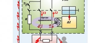
The difference between an RCD and a circuit breaker is that it has a leakage current protection function; a circuit breaker does not have such protection. The RCD contains a differential transformer, which determines the difference in the current of the phase and neutral wires during current leakage.
These currents, amplified by the secondary winding of the differential transformer, are supplied to a polarized relay associated with the trigger, which turns off the protection. Thus, the RCD device is protected against leakage currents.
Residual current devices
Leakage currents can occur when the insulation of a wire breaks down on the housing of electrical household appliances and a person touches it. In this case, this type of protection saves a person’s life. The operation of the RCD is based on determining the difference between the phase and zero currents, so it has two terminals for connecting the phase and zero, and two more terminals for the phase and zero output for connecting the load.
That is, this device is two-pole for a single-phase network, and for a three-phase network it is four-pole. Also, an RCD differs from a simple machine in that it has a test button to check its functionality. The machine for a single-phase network has a single-pole module, and for a three-phase network it has a four-pole module.
Operating principle
According to the principle of operation, a two-pole circuit breaker is not particularly disconnected from single-pole or three-pole versions of the device. In an emergency, the circuit breaker instantly cuts off the electrical current, shutting down the device connected to it and protecting it from damage.
The main feature of a two-pole circuit breaker is that both circuit lines pass through it. If a fault occurs on any of the lines, regardless of whether it is zero or phase, the device turns off both at the same time, which simultaneously ensures the safety of the unit, since the circuit is instantly broken, cutting off the power completely, and greater convenience when troubleshooting.
Thus, a two-pole circuit breaker is the most important element of protecting the network from overcurrents. If you are not sure of a constant phase or you need to power complex equipment with high energy consumption, you should not hesitate to install a two-pole circuit breaker, otherwise repair costs may be high. And also, do not forget that the device does not protect devices connected to a given network, but only saves the network itself from overcurrents that occur during a short circuit. And it is better to trust any connections of machines to a professional electrician.
Read also: Schemes of esr meters on k572pv5
Hello! I am doing wiring at the dacha and the question arose of choosing an input device to protect it. Tell me, how does a two-pole circuit breaker differ from a single-pole one, and can it be replaced with a pair of single-pole devices?
Time-current characteristic
What does this physical indicator mean? In principle, everything is quite simple. When the network is overloaded, especially when the load depends on the starting torque of the household appliance, the machine turns off. But since this load is short-term, sometimes there is no need to turn off the power supply. It turns out that the machine allows the device to turn on, and at the same time it does not cut off the supply of electricity to the electrical wiring of the building.
But there is one caveat. How long does it take for a household appliance to enter normal operating mode, and how quickly does it turn on? That is, how long will the inrush current last? It is the time indicator that is included in this characteristic of the circuit breaker. This creates conditions under which the shutdown of the machine will be reduced.
There are several machines with different time-current loads.
- Type-A. This device is used in linear networks in which the length of the electrical wiring is very long, or where semiconductor devices are installed. Withstands overload 2-3 times.
- Type-B. Usually installed in a network with an active load and a low multiplicity of the starting current torque. Typically, such machines are used in areas where lighting, stoves, heaters, and so on are installed. Overload is 3-5 rated loads.
- Type-S. Mounted in networks with moderate current loads. These are usually socket groups where air conditioners and refrigerators are connected. Withstands exceeding the nominal value by 5-10 times.
- Type-D. Used in circuits where units with high starting current are installed. These can be compressors, pumps, small machines. The excess is 10-20 denominations.
- Type-K. used in electrical circuits with inductive loads. Excess: 8-12.
- Type-Z. Such machines are installed in circuits into which electronic devices are connected. They are sensitive to overcurrents.
If we talk about domestic use, then most often types “B” and “C” are installed in electrical wiring, rarely “D”.
So, how to determine both characteristics on the circuit breaker itself? Usually on the case you can find the following designation: “C16” or any other, the main thing is that it is a letter of the Latin alphabet and a number. This indicates (in this case) that the current rating of the circuit breaker is 16 amperes, and the time-current characteristic classifies this device as type “C”. That is, this machine will withstand a current of 80-160 amperes for some time. Typically, the response time of the machine is 0.1 seconds.
How to calculate the rated current of a circuit breaker? Everything is quite simple. Let's look at this calculation using the example of a socket group where an electric kettle with a power of 1.5 kW, a refrigerator with a power of 400 W and a dishwasher with a power of 2.5 kW are connected.
First of all, it is necessary to determine the total power of consumers, which is equal to 4.4 kW. Now we insert all the indicators into the formula of Ohm’s law:
I=P/U=4400. 220=20 A. We have a machine with such a current load in our catalog, but it is necessary to take into account the conditions that were specified in the article above. That is, it is better to choose a circuit breaker with a higher current rating. And this will be 25 amperes.
Circuit breakers - technical characteristics and the right choice according to them
Characteristics of electric machines
What is the danger of a cable mismatch with the network load?
Selecting the correct power circuit breaker is a very important task. An incorrectly selected device will not protect the line from a sudden increase in current.
But it is equally important to choose the correct cross-section of the electrical cable. Otherwise, if the total power exceeds the rated value that the conductor can withstand, this will lead to a significant increase in the temperature of the latter
As a result, the insulating layer will begin to melt, which can lead to a fire.
To more clearly imagine the consequences of a mismatch between the wiring cross-section and the total power of the devices connected to the network, let’s consider this example.
New owners, having bought an apartment in an old house, install several modern household appliances in it, giving a total load on the circuit equal to 5 kW. The current equivalent in this case will be about 23 A. In accordance with this, a 25 A circuit breaker is included in the circuit. It would seem that the choice of the circuit breaker in terms of power was made correctly, and the network is ready for operation. But some time after turning on the appliances, smoke appears in the house with a characteristic smell of burnt insulation, and after a while a flame appears. The circuit breaker will not disconnect the network from the power supply - after all, the current rating does not exceed the permissible one.
If the owner is not nearby at this moment, the melted insulation will cause a short circuit after some time, which will finally trigger the machine, but the flames from the wiring may already spread throughout the house.
So that you do not have to take out a calculator and independently calculate the cross-section of electrical wiring using formulas, we present a standard table in which it is easy to find the desired value.
Basic criteria for choosing a circuit breaker
Short circuit current limit
This indicator must be taken into account immediately. It means the maximum current value at which the electrical circuit breaker will operate and open the circuit. There is not much choice here, since there are only three options: 4.5 kA
;
6 kA
;
10kA
.
When choosing, you should be guided by the theoretical probability of occurrence of a strong short-circuit current. If there is no such probability, then it will be enough to purchase a 4.5 kA automatic machine.
Machine current
Taking this indicator into account is the next step. We are talking about the required nominal value of the operating current of the electrical machine. To determine the operating current, you need to be guided by the power that is expected to be connected to the wiring, or by the value of the permissible current (the level that will be maintained in normal mode).
What do you need to know when determining the parameter in question? It is not recommended to use machines with high operating current. It’s just that in this case, the machine will not turn off the power when overloaded, and this can cause thermal destruction of the wiring insulation.
Machine polarity
This is perhaps the simplest indicator. To choose the number of poles for a switch, you need to proceed from how it will be used.
So, a single-pole circuit breaker is your choice if you need to protect the wiring that goes from the electrical panel to sockets and lighting circuits. A two-pole switch is used when you need to protect all wiring in an apartment or house with single-phase power. Protection of three-phase wiring and load is provided by a three-pole circuit breaker, and four-pole circuit breakers are used to protect four-wire power.
Machine characteristics
This is the last indicator you need to pay attention to. The time-current characteristic of the circuit breaker is determined by the loads that are connected to the protected line. When choosing characteristics, the following are taken into account: operating current of the circuit, rated current of the machine, cable capacity, operating current of the switch.
In the event that it is necessary to connect small inrush currents to the power supply line, i.e. electrical devices characterized by a small difference between the operating current and the current that occurs when turned on, preference should be given to response characteristic B. For more serious loads, characteristic C is chosen. Finally, there is another characteristic - D. Your choice should be made on it because if you plan to connect powerful devices with high trigger points. What devices are we talking about? For example, about an electric motor.