Home » Question answer » Electric and magnetic field: what are the differences
A term such as “field” in our language has a general, fairly broad concept (for example, potato or football). But in the exact sciences, such as physics and electrical engineering, this name is used to describe certain types of matter. Thus, electromagnetic matter consists of two components: electrical and magnetic.
Electric charge is directly associated with these forms of matter. And this charge has a characteristic feature. In a stationary state, an electric field constantly exists around it, and as soon as the charge begins to move in a direction, a magnetic field also appears. Let us consider the characteristic features of electric and magnetic fields separately.
What is an electric field?
In physics, this concept is usually understood as a vector field that is formed around particles or bodies with a certain charge. The electric field is considered one of the two integral components of the electromagnetic field.
To better understand the nature of this phenomenon, you need to remember what the Coulomb force is. Coulomb's law serves to determine the degree of interaction between each of a pair of point electric charges. At the same time, it takes into account information about the interval between them.
To understand the tension of the phenomenon, it is worth turning to this example:
- There are 2 bodies that have a charge. In this case, one of them is stationary, and the second moves around the first.
- The Coulomb force in this case is equal to the product of charge and voltage.
- The tension will include the central charge parameter and the square of the distance from the center to the second body.
It is noteworthy that for each point of the electric field the Coulomb force parameter and direction will be different. Due to the difference in directions at different points, the concept is considered vector.
Units
The units for measuring electric and magnetic field strength are also different. Magnetic field strength is represented by Gauss or Tesla. Electric field strength is represented by Newton per coulomb or Volt per meter.
However, both concepts are perfectly interrelated and have played an important role in many innovative developments. Their relationship can be clearly explained using Maxwell's equations, a system of partial differential equations that relate electric and magnetic fields to their sources, current density, and charge density.
Source
What is a magnetic field?
In physics, this term is understood as a force field that affects exclusively moving bodies, particles or charges. Each element is characterized by a magnetic moment. The force in this case depends less on the movement of the charge. In this case, electrons act as charged particles. As for the strength of this type of field, the value will be in direct proportion to the speed of the charge and its parameters.
The best example is planet Earth. Its central part consists of red-hot iron. Like other metal objects, it can move electrons around it. That is why the largest magnetic field on Earth is formed by the planet itself, or its center, to be more precise. If this field disappears, there is a high probability of disasters and even the death of living organisms.
Expert opinion
Karnaukh Ekaterina Vladimirovna
Graduated from the National University of Shipbuilding, majoring in Enterprise Economics
A more standard example of such a concept is electromagnets. They typically involve wires that are wrapped around ferromagnets. These elements are a series of substances that acquire magnetic characteristics only if their temperature is below a specific level. The last parameter is called the Cure temperature in physics. In fact, ferromagnets are considered unique elements. They interact with the magnetic field, but do not carry moving charges.
Electricity and magnetism
Electric field strength
Electric field strength is a vector characteristic of the field, a force acting on a unit electric charge at rest in a given reference frame.
Tension is determined by the formula:
$E↖{→}={F↖{→}}/{q}$
where $E↖{→}$ is the field strength; $F↖{→}$ is the force acting on the charge $q$ placed at a given point in the field. The direction of the vector $E↖{→}$ coincides with the direction of the force acting on the positive charge and is opposite to the direction of the force acting on the negative charge.
The SI unit of voltage is volt per meter (V/m).
Field strength of a point charge.
According to Coulomb's law, a point charge $q_0$ acts on another charge $q$ with a force equal to
$F=k{|q_0||q|}/{r^2}$
The modulus of the field strength of a point charge $q_0$ at a distance $r$ from it is equal to
$E={F}/{q}=k{|q_0|}/{r^2}$
The intensity vector at any point of the electric field is directed along the straight line connecting this point and the charge.
Electric field lines
The electric field in space is usually represented by lines of force. The concept of lines of force was introduced by M. Faraday while studying magnetism. This concept was then developed by J. Maxwell in his research on electromagnetism.
A line of force, or electric field strength line, is a line whose tangent at each point coincides with the direction of the force acting on a positive point charge located at that point in the field.
Tension lines of a positively charged ball;
Tension lines of two oppositely charged balls;
Tension lines of two similarly charged balls
Tension lines of two plates charged with charges of different signs, but equal in absolute value.
The tension lines in the last figure are almost parallel in the space between the plates, and their density is the same. This suggests that the field in this region of space is uniform. An electric field is called homogeneous if its strength is the same at all points in space.
In an electrostatic field, the lines of force are not closed; they always begin on positive charges and end on negative charges. They do not intersect anywhere; the intersection of the field lines would indicate the uncertainty of the direction of the field strength at the intersection point. The density of field lines is greater near charged bodies, where the field strength is greater.
Field of a charged ball.
The field strength of a charged conducting ball at a distance from the center of the ball exceeding its radius $r≥R$ is determined by the same formula as the fields of a point charge. This is evidenced by the distribution of field lines, similar to the distribution of intensity lines of a point charge.
The charge of the ball is distributed evenly over its surface. Inside the conducting ball, the field strength is zero.
A magnetic field. Magnet interaction
The phenomenon of interaction between permanent magnets (the establishment of a magnetic needle along the Earth’s magnetic meridian, the attraction of unlike poles, the repulsion of like poles) has been known since ancient times and was systematically studied by W. Gilbert (the results were published in 1600 in his treatise “On the Magnet, Magnetic Bodies and the Great Magnet - Earth").
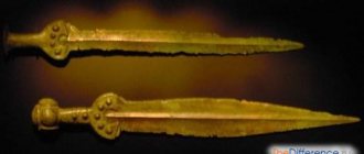
Natural (natural) magnets
The magnetic properties of some natural minerals were known already in ancient times. Thus, there is written evidence from more than 2000 years ago about the use of natural permanent magnets as compasses in China. The attraction and repulsion of magnets and the magnetization of iron filings by them is mentioned in the works of ancient Greek and Roman scientists (for example, in the poem “On the Nature of Things” by Lucretius Cara).
Natural magnets are pieces of magnetic iron ore (magnetite), consisting of $FeO$ (31%) and $Fe_2O$ (69%). If such a piece of mineral is brought close to small iron objects - nails, sawdust, a thin blade, etc., they will be attracted to it.
Artificial permanent magnets
Permanent magnet
- this is a product made of a material that is an autonomous (independent, isolated) source of a constant magnetic field.
Artificial permanent magnets are made from special alloys, which include iron, nickel, cobalt, etc. These metals acquire magnetic properties (magnetize) if they are brought close to permanent magnets. Therefore, in order to make permanent magnets from them, they are specially kept in strong magnetic fields, after which they themselves become sources of a constant magnetic field and are able to retain magnetic properties for a long time.
The figure shows an arc and strip magnets.
In Fig. pictures of the magnetic fields of these magnets are given, obtained by the method that M. Faraday first used in his research: with the help of iron filings scattered on a sheet of paper on which the magnet lies. Each magnet has two poles - these are the places of greatest concentration of magnetic field lines (they are also called magnetic field lines
, or
lines of magnetic field induction
).
These are the places that iron filings are most attracted to. One of the poles is usually called the north
(($N$), the other -
the south
($S$). If you bring two magnets to each other with like poles, you can see that they repel, and if they have opposite poles, they attract.
In Fig. it is clearly visible that the magnetic lines of a magnet are closed lines
.
The magnetic field lines of two magnets facing each other with like and unlike poles are shown. The central part of these paintings resembles patterns of electric fields of two charges (opposite and like). However, a significant difference between electric and magnetic fields is that electric field lines begin and end at charges. Magnetic charges do not exist in nature. The magnetic field lines leave the north pole of the magnet and enter the south; they continue in the body of the magnet, i.e., as mentioned above, they are closed lines. Fields whose field lines are closed are called vortex
. A magnetic field is a vortex field (this is its difference from an electric one).
Application of magnets
The most ancient magnetic device is the well-known compass. In modern technology, magnets are used very widely: in electric motors, in radio engineering, in electrical measuring equipment, etc.
Earth's magnetic field
The globe is a magnet. Like any magnet, it has its own magnetic field and its own magnetic poles. That is why the compass needle is oriented in a certain direction. It is clear where exactly the north pole of the magnetic needle should point, because opposite poles attract
. Therefore, the north pole of the magnetic needle points to the south magnetic pole of the Earth. This pole is located in the north of the globe, somewhat away from the north geographic pole (on Prince of Wales Island - about $75°$ north latitude and $99°$ west longitude, at a distance of approximately $2100$ km from the north geographic pole).
When approaching the north geographic pole, the lines of force of the Earth's magnetic field increasingly tilt toward the horizon at a greater angle, and in the region of the south magnetic pole they become vertical.
The Earth's north magnetic pole is located near the south geographic pole, namely at $66.5°$ south latitude and $140°$ east longitude. Here the magnetic field lines exit the Earth.
In other words, the Earth's magnetic poles do not coincide with its geographic poles. Therefore, the direction of the magnetic needle does not coincide with the direction of the geographic meridian, and the magnetic needle of the compass only approximately shows the direction to the north.
The compass needle can also be affected by some natural phenomena, for example, magnetic storms,
which are temporary changes in the Earth's magnetic field associated with solar activity. Solar activity is accompanied by the emission of streams of charged particles, in particular electrons and protons, from the surface of the Sun. These flows, moving at high speed, create their own magnetic field that interacts with the Earth's magnetic field.
On the globe (except for short-term changes in the magnetic field) there are areas in which there is a constant deviation in the direction of the magnetic needle from the direction of the Earth's magnetic line. These are areas of magnetic anomaly
(from the Greek anomalia - deviation, abnormality). One of the largest such areas is the Kursk magnetic anomaly. The anomalies are caused by huge deposits of iron ore at a relatively shallow depth.
The Earth's magnetic field reliably protects the Earth's surface from cosmic radiation, the effect of which on living organisms is destructive.
Flights of interplanetary space stations and ships have made it possible to establish that the Moon and the planet Venus have no magnetic field, while the planet Mars has a very weak one.
Experiments by Oerstedai Ampere. Magnetic field induction
In 1820, the Danish scientist G. H. Oersted discovered that a magnetic needle placed near a conductor through which current flows rotates, tending to be perpendicular to the conductor.
The diagram of G. H. Oersted's experiment is shown in the figure. The conductor included in the current source circuit is located above the magnetic needle parallel to its axis. When the circuit is closed, the magnetic needle deviates from its original position. When the circuit is opened, the magnetic needle returns to its original position. It follows that the current-carrying conductor and the magnetic needle interact with each other. Based on this experiment, we can conclude that there is a magnetic field associated with the flow of current in a conductor and the vortex nature of this field. The described experiment and its results were Oersted's most important scientific achievement.
In the same year, the French physicist Ampere, who was interested in Oersted's experiments, discovered the interaction of two straight conductors with current. It turned out that if the currents in the conductors flow in one direction, i.e., they are parallel, then the conductors attract, if in opposite directions (i.e., they are antiparallel), then they repel.
Interactions between current-carrying conductors, i.e., interactions between moving electric charges, are called magnetic, and the forces with which current-carrying conductors act on each other are called magnetic forces.
According to the theory of short-range action, which M. Faraday adhered to, the current in one of the conductors cannot directly affect the current in the other conductor. Similar to the case with stationary electric charges around which there is an electric field, it was concluded that in the space surrounding the currents there is a magnetic field,
which acts with some force on another current-carrying conductor placed in this field, or on a permanent magnet. In turn, the magnetic field created by the second current-carrying conductor acts on the current in the first conductor.
Just as an electric field is detected by its effect on a test charge introduced into this field, a magnetic field can be detected by the orienting effect of a magnetic field on a frame with a current of small (compared to the distances at which the magnetic field changes noticeably) dimensions.
The wires supplying current to the frame should be intertwined (or placed close to each other), then the resulting force exerted by the magnetic field on these wires will be zero. The forces acting on such a current-carrying frame will rotate it so that its plane becomes perpendicular to the magnetic field induction lines. In the example, the frame will rotate so that the current-carrying conductor is in the plane of the frame. When the direction of current in the conductor changes, the frame will rotate $180°$. In the field between the poles of a permanent magnet, the frame will turn with a plane perpendicular to the magnetic lines of force of the magnet.
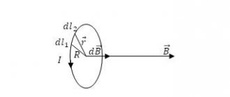
Magnetic induction
Magnetic induction ($В↖{→}$) is a vector physical quantity that characterizes the magnetic field.
The direction of the magnetic induction vector $B↖{→}$ is taken to be:
1) the direction from the south pole $S$ to the north pole $N$ of a magnetic needle freely positioned in a magnetic field, or
2) the direction of the positive normal to a closed circuit with current on a flexible suspension, freely installed in a magnetic field. The normal directed towards the movement of the tip of the gimlet (with a right-hand thread), the handle of which is rotated in the direction of the current in the frame, is considered positive.
It is clear that directions 1) and 2) coincide, which was established by Ampere’s experiments.
As for the magnitude of magnetic induction (i.e., its modulus) $B$, which could characterize the strength of the field, experiments have established that the maximum force $F$ with which the field acts on a current-carrying conductor (placed perpendicular to the induction lines magnetic field), depends on the current $I$ in the conductor and on its length $∆l$ (proportional to them). However, the force acting on a current element (of unit length and current strength) depends only on the field itself, i.e. the ratio ${F}/{I∆l}$ for a given field is a constant value (similar to the ratio of force to charge for electric field). This quantity is defined as magnetic induction
.
$B={F}/{I∆l}$
The magnetic field induction at a given point is equal to the ratio of the maximum force acting on a current-carrying conductor to the length of the conductor and the current strength in the conductor placed at this point.
The greater the magnetic induction at a given point in the field, the greater the force the field at that point will act on a magnetic needle or a moving electric charge.
The SI unit of magnetic induction is the tesla
(Tl), named after the Serbian electrical engineer Nikola Tesla. As can be seen from the formula, $1$ T $=l{H}/{A m}$
If there are several different sources of magnetic field, the induction vectors of which at a given point in space are equal to ${В_1}↖{→}, {В_2}↖{→}, {В_3}↖{→},...$, then, according to the principle of field superposition
, the magnetic field induction at this point is equal to the sum of the magnetic field induction vectors created
by each source
.
$В↖{→}={В_1}↖{→}+{В_2}↖{→}+{В_3}↖{→}+…$
Magnetic induction lines
For a visual representation of the magnetic field, M. Faraday introduced the concept of magnetic lines of force,
which he repeatedly demonstrated in his experiments. A picture of the field lines can easily be obtained using iron filings sprinkled on cardboard. The figure shows: lines of magnetic induction of direct current, solenoid, circular current, direct magnet.
Magnetic induction lines
, or
magnetic lines of force
, or simply
magnetic lines
, are lines whose tangents at any point coincide with the direction of the magnetic induction vector $B↖{→}$ at that point in the field.
If, instead of iron filings, small magnetic needles are placed around a long straight conductor carrying current, then you can see not only the configuration of the field lines (concentric circles), but also the direction of the field lines (the north pole of the magnetic needle indicates the direction of the induction vector at a given point).
The direction of the magnetic field of the forward current can be determined by the right-hand gimlet rule.
If you rotate the handle of the gimlet so that the translational movement of the tip of the gimlet indicates the direction of the current, then the direction of rotation of the handle of the gimlet will indicate the direction of the magnetic field lines of the current.
The direction of the magnetic field of the forward current can also be determined using the first right-hand rule.
If you grasp the conductor with your right hand, pointing the bent thumb in the direction of the current, then the tips of the remaining fingers at each point will show the direction of the induction vector at that point.
Vortex field
Magnetic induction lines are closed, which indicates that there are no magnetic charges in nature. Fields whose field lines are closed are called vortex fields
. That is, the magnetic field is a vortex field. This differs from the electric field created by charges.
Solenoid
A solenoid is a coil of wire carrying current.
The solenoid is characterized by the number of turns per unit length $n$, length $l$ and diameter $d$. The thickness of the wire in the solenoid and the pitch of the helix (helical line) are small compared to its diameter $d$ and length $l$. The term “solenoid” is also used in a broader sense - this is the name given to coils with an arbitrary cross-section (square solenoid, rectangular solenoid), and not necessarily cylindrical in shape (toroidal solenoid). There are long solenoid ($l>>d$) and short ($l
The solenoid was invented in 1820 by A. Ampere to enhance the magnetic action of current discovered by X. Oersted and used by D. Arago in experiments on the magnetization of steel rods. The magnetic properties of a solenoid were experimentally studied by Ampere in 1822 (at the same time he introduced the term “solenoid”). The equivalence of the solenoid to permanent natural magnets was established, which was a confirmation of Ampere’s electrodynamic theory, which explained magnetism by the interaction of ring molecular currents hidden in bodies.
The magnetic field lines of the solenoid are shown in the figure. The direction of these lines is determined using the second rule of the right hand.
If you clasp the solenoid with the palm of your right hand, directing four fingers along the current in the turns, then the extended thumb will indicate the direction of the magnetic lines inside the solenoid.
Comparing the magnetic field of a solenoid with the field of a permanent magnet, you can see that they are very similar. Like a magnet, a solenoid has two poles - north ($N$) and south ($S$). The North Pole is the one from which magnetic lines emerge; the south pole is the one they enter. The north pole of the solenoid is always located on the side that the thumb of the palm points to when it is positioned in accordance with the second rule of the right hand.
A solenoid in the form of a coil with a large number of turns is used as a magnet.
Studies of the magnetic field of a solenoid show that the magnetic effect of the solenoid increases with increasing current and the number of turns in the solenoid. In addition, the magnetic effect of a solenoid or current-carrying coil is enhanced by inserting an iron rod called a core into it.
Electromagnets
A solenoid with an iron core inside is called an electromagnet.
Electromagnets can contain not one, but several coils (windings) and have cores of different shapes.
Such an electromagnet was first constructed by the English inventor W. Sturgeon in 1825. With a mass of $0.2$ kg, W. Sturgeon’s electromagnet held a load weighing $36$ N. In the same year, J. Joule increased the lifting force of the electromagnet to $200$ N, and six years later American scientist J. Henry built an electromagnet weighing $300$ kg, capable of holding a load weighing $1$ t!
Modern electromagnets can lift loads weighing several tens of tons. They are used in factories when moving heavy iron and steel products. Electromagnets are also used in agriculture to clean the grains of a number of plants from weeds and in other industries.
Ampere power
A straight section of conductor $∆l$, through which current $I$ flows, is acted upon by a force $F$ in a magnetic field with induction $B$.
To calculate this force, use the expression:
$F=B|I|∆lsinα$
where $α$ is the angle between the vector $B↖{→}$ and the direction of the section of conductor with current (current element); The direction of the current element is taken to be the direction in which the current flows through the conductor. The force $F$ is called the Ampere force
in honor of the French physicist A. M. Ampere, who was the first to discover the effect of a magnetic field on a current-carrying conductor. (In fact, Ampere established a law for the force of interaction between two elements of current-carrying conductors. He was a proponent of the theory of long-range action and did not use the concept of field.
However, according to tradition and in memory of the scientist’s merits, the expression for the force acting on a current-carrying conductor from a magnetic field is also called Ampere’s law.)
The direction of Ampere's force is determined using the left-hand rule.
If you position the palm of your left hand so that the magnetic field lines enter it perpendicularly, and the four extended fingers indicate the direction of the current in the conductor, then the outstretched thumb will indicate the direction of the force acting on the current-carrying conductor. Thus, the Ampere force is always perpendicular to both the magnetic field induction vector and the direction of the current in the conductor, i.e., perpendicular to the plane in which these two vectors lie.
The consequence of the Ampere force is the rotation of the current-carrying frame in a constant magnetic field. This finds practical application in many devices, such as electrical measuring instruments
- galvanometers, ammeters, where a movable frame with current rotates in the field of a permanent magnet and by the angle of deflection of a pointer fixedly connected to the frame, one can judge the amount of current flowing in the circuit.
Thanks to the rotating effect of the magnetic field on the current-carrying frame, it also became possible to create and use electric motors
- machines in which electrical energy is converted into mechanical energy.
Lorentz force
The Lorentz force is a force acting on a moving point electric charge in an external magnetic field.
Dutch physicist H. A. Lorenz at the end of the 19th century. established that the force exerted by a magnetic field on a moving charged particle is always perpendicular to the direction of motion of the particle and the lines of force of the magnetic field in which this particle moves.
The direction of the Lorentz force can be determined using the left-hand rule.
If you position the palm of your left hand so that the four extended fingers indicate the direction of movement of the charge, and the vector of the magnetic induction field enters the palm, then the extended thumb will indicate the direction of the Lorentz force acting on the positive charge.
If the charge of the particle is negative, then the Lorentz force will be directed in the opposite direction.
The modulus of the Lorentz force is easily determined from Ampere's law and is:
$F=|q|υBsinα$
where $q$ is the charge of the particle, $υ$ is the speed of its movement, $α$ is the angle between the velocity and magnetic field induction vectors.
If, in addition to the magnetic field, there is also an electric field that acts on the charge with a force ${F_{el}}↖{→}=qE↖{→}$, then the total force acting on the charge is equal to:
$F↖{→}={F_{el}}↖{→}+{F_l}↖{→}$
Often it is this total force that is called the Lorentz force, and the force expressed by the formula $F=|q|υBsinα$ is called the magnetic part of the Lorentz force.
Since the Lorentz force is perpendicular to the direction of motion of the particle, it cannot change its speed (it does no work), but can only change the direction of its motion, i.e., bend the trajectory.
This curvature of the trajectory of electrons in a TV picture tube is easy to observe if you bring a permanent magnet to its screen: the image will be distorted.
Motion of a charged particle in a uniform magnetic field.
Let a charged particle fly with a speed $υ$ into a uniform magnetic field perpendicular to the tension lines. The force exerted by the magnetic field on the particle will cause it to rotate uniformly in a circle of radius r, which is easy to find using Newton’s second law, the expression for centripetal acceleration and the formula $F=|q|υBsinα$:
${mυ^2}/{r}=|q|υB$
From here we get
$r={mυ}/{|q|B}$
where $m$ is the particle mass.
Application of the Lorentz force.
The effect of a magnetic field on moving charges is used, for example, in
mass spectrographs
, which make it possible to separate charged particles by their specific charges, i.e., by the ratio of the charge of a particle to its mass, and from the results obtained accurately determine the masses of the particles.
The vacuum chamber of the device is placed in a field (the induction vector $B↖{→}$ is perpendicular to the figure). Charged particles (electrons or ions) accelerated by the electric field, having described an arc, fall on the photographic plate, where they leave a trace that allows the radius of the trajectory $r$ to be measured with great accuracy. This radius determines the specific charge of the ion. Knowing the charge of an ion, it is easy to calculate its mass.
Magnetic properties of substances
In order to explain the existence of the magnetic field of permanent magnets, Ampere suggested that microscopic circular currents exist in a substance with magnetic properties (they were called molecular
). This idea was subsequently, after the discovery of the electron and the structure of the atom, brilliantly confirmed: these currents are created by the movement of electrons around the nucleus and, being oriented in the same way, in total create a field around and inside the magnet.
In Fig. the planes in which elementary electric currents are located are randomly oriented due to the chaotic thermal motion of atoms, and the substance does not exhibit magnetic properties. In a magnetized state (under the influence, for example, of an external magnetic field), these planes are oriented identically, and their actions add up.
Magnetic permeability.
The reaction of the medium to the influence of an external magnetic field with induction $B_0$ (field in a vacuum) is determined by the magnetic susceptibility $μ$:
$μ={B}/{B_0}$
where $B$ is the magnetic field induction in the substance. Magnetic permeability is similar to dielectric constant $ε$.
Based on their magnetic properties, substances are divided into diamagnetic, paramagnetic and ferromagnetic.
. For diamagnetic materials, the coefficient $μ$, which characterizes the magnetic properties of the medium, is less than $1$ (for example, for bismuth $μ = 0.999824$); for paramagnets $μ > 1$ (for platinum $μ = 1.00036$); for ferromagnets $μ >> 1$ (iron, nickel, cobalt).
Diamagnets are repelled by a magnet, paramagnetic materials are attracted. By these characteristics they can be distinguished from each other. For most substances, the magnetic permeability practically does not differ from unity, only for ferromagnets it greatly exceeds it, reaching several tens of thousands of units.
Ferromagnets.
Ferromagnets exhibit the strongest magnetic properties.
The magnetic fields created by ferromagnets are much stronger than the external magnetizing field. True, the magnetic fields of ferromagnets are created not as a result of the rotation of electrons around the nuclei - orbital magnetic moment
, but as a result of the electron’s own rotation - its own magnetic moment, called
spin.
The Curie temperature ($T_c$) is the temperature above which ferromagnetic materials lose their magnetic properties. It is different for each ferromagnet. For example, for iron $Т_с = 753°$С, for nickel $Т_с = 365°$С, for cobalt $Т_с = 1000°$ С. There are ferromagnetic alloys with $Т_с
The first detailed studies of the magnetic properties of ferromagnets were carried out by the outstanding Russian physicist A. G. Stoletov (1839-1896).
Ferromagnets are used very widely: as permanent magnets (in electrical measuring instruments, loudspeakers, telephones, etc.), steel cores in transformers, generators, electric motors (to enhance the magnetic field and save electricity). Magnetic tapes made from ferromagnetic materials record sound and images for tape recorders and video recorders. Information is recorded on thin magnetic films for storage devices in electronic computers.
Lenz's rule
Lenz's rule (Lenz's law) was established by E. H. Lenz in 1834. It refines the law of electromagnetic induction, discovered in 1831 by M. Faraday. Lenz's rule determines the direction of the induced current in a closed loop as it moves in an external magnetic field.
The direction of the induction current is always such that the forces it experiences from the magnetic field counteract the movement of the circuit, and the magnetic flux $Ф_1$ created by this current tends to compensate for changes in the external magnetic flux $Ф_e$.
Lenz's law is an expression of the law of conservation of energy for electromagnetic phenomena. Indeed, when a closed loop moves in a magnetic field due to external forces, it is necessary to perform some work against the forces arising as a result of the interaction of the induced current with the magnetic field and directed in the direction opposite to the movement.
Lenz's rule is illustrated in the figure. If a permanent magnet is moved into a coil closed to a galvanometer, the induced current in the coil will have a direction that will create a magnetic field with vector $B'$ directed opposite to the induction vector of the magnet's field $B$, i.e. it will push the magnet out of the coil or impede its movement. When a magnet is pulled out of a coil, on the contrary, the field created by the induction current will attract the coil, i.e., again impede its movement.
To apply Lenz's rule to determine the direction of the induced current $I_e$ in the circuit, you must follow these recommendations.
- Set the direction of the magnetic induction lines $B↖{→}$ of the external magnetic field.
- Find out whether the flux of magnetic induction of this field through the surface bounded by the contour ($∆Ф > 0$) increases or decreases ($∆Ф
- Set the direction of the magnetic induction lines $B'↖{→}$ of the magnetic field of the induced current $I_i$. These lines must be directed, according to Lenz’s rule, opposite to the lines $В↖{→}$ if $∆Ф > 0$, and have the same direction as them if $∆Ф
- Knowing the direction of the magnetic induction lines $B'↖{→}$, determine the direction of the induced current $I_i$ using the gimlet rule.
What is the difference between an electric field and a magnetic field?
Both concepts under consideration are considered power. This means that at each point in space where the field acts, a specific force affects the charge. At another point its value will be different. The electromagnetic field affects charged bodies and particles. Moreover, it acts on all charges, while the magnetic field acts exclusively on moving ones.
There are substances that interact with a magnetic field, but do not involve moving charges. These include, in particular, ferromagnets. This concept differs from the electric field, since similar substances do not exist for it. Magnets, natural or magnetized bodies, have 2 poles. They are called southern and northern.
Expert opinion
Karnaukh Ekaterina Vladimirovna
Graduated from the National University of Shipbuilding, majoring in Enterprise Economics
Ordinary electric charges are considered relatively homogeneous. They do not include poles. Moreover, such charges are characterized by 2 types - positive and negative. The sign affects the direction of the Coulomb force. As a consequence, this affects the interaction of two charged particles. The sign will not affect the interaction of other charged particles with the magnetic field. It will only reverse the poles.
The graphic representation of the physical phenomena under consideration is also different. Electric field lines have a beginning and an end. They can be visualized. An example is quinine crystals in oil. The induction lines are closed. They can also be visualized. An example of this is metal filings.
Separately, it is worth mentioning the electromagnetic field, which has the characteristics of both an electric and a magnetic field. This means that it is capable, under certain conditions, of turning the compass needle and moving electrically charged particles. Both components have a close relationship with each other. Each of them differs in its energy reserve. It is this that influences the energy of the entire electromagnetic field.
Expert opinion
Karnaukh Ekaterina Vladimirovna
Graduated from the National University of Shipbuilding, majoring in Enterprise Economics
The emergence of an electromagnetic field is possible with any, even small, change in current in conductors. At the same time, it influences the adjacent zones of space and transfers its own energy to them. As a result, an electromagnetic field also appears in these places.
"The legislative framework"
The study of fields, magnetic and electric, is carried out according to previously discovered physical laws. Thus, for the electric field, when studying the processes occurring within it, the research and experiments carried out by the pendant provided invaluable assistance. It is easier to imagine the magnetic field using Ampere's law in relation to the location of the human palm. So, in order to determine the direction of the force acting on the conductor, it is necessary to position the palm as follows:
– 4 fingers folded together indicate the direction of the current flow;
– magnetic field lines enter the palm;
– the thumb, located at an angle of 90 degrees relative to the other fingers of the palm, will indicate the direction of the desired force.
comparison table
The main features and differences of the concepts under consideration are shown in the table:
| Criterion | Electric field | A magnetic field |
| Field Source | Electric charge. | Magnet, current. |
| Field detection | When charged particles interact. | When magnets and conductors interact with current. |
| Graphic image | Lines of force or lines of tension. | Lines of force or lines of magnetic induction. |
| Character of lines | They have a beginning and an end. The beginning of the lines of force is on positive charges, and the end is on negative charges. | They are closed. The lines leave the north pole and enter the south pole. They are closed in the magnet. |
| Interaction of elements | Charged particles of the same name attract, charged particles of the same name repel. | Opposite magnetic poles attract, like magnetic poles repel. |
| Power characteristic | The tension vector is measured in newtons per coulomb. | Magnetic induction vector, unit of measurement is tesla. |
| Field indicators | Small pieces of paper Electric Sultan Electric sleeve. | Metal filings Magnetic needle Closed circuit with current. |
| Superposition principle | The field strength at a certain point is equal to the vector sum of the field strengths that are created by each of the charges separately. | The magnetic induction of the resulting field is the vector sum of the induction of fields that are created by each source separately. |
Two fields
- An electric field is formed around any bodies or particles that have a certain amount of electric charge. If certain changes in the parameters of the magnetic field occur, this process is accompanied by the movement of electromagnetic waves. For clarity, in the diagrams such fields are depicted in the form of lines of force (dotted lines), which begin at positively charged particles and end with arrows touching negatively charged particles. It is the charges here that are the basis for the existence of the electric field.
In the process of conducting research and for the purpose of more effective practical application of this phenomenon, it was given the name tension. It is assessed by the degree of impact on a single (positive sign) charge.
- The magnetic field has a different type of effect, primarily on various electrical bodies and charges that are in motion. Magnetic moments are taken into account without determining the actual magnitude of the movement, and the field itself is created during the passage of a current of charged particles. The field strength is the sum of the magnetic moments of electrons located inside atoms or other particles.
The method of graphical representation using dotted power lines is also used here. But unlike the schematic representation of the electric field, these lines are closed along a contour and do not have a specific starting point (as well as an end).