Many lighting systems have been using fluorescent lamps for a long time. They are distinguished by their efficiency, high performance and technical characteristics. Currently, compact devices have appeared in which the control system is freely located in the housing. Such lamps can be used in conventional lamps with threaded sockets.
Due to the design features and the use of ballasts, sometimes malfunctions occur during long-term operation, and then you have to repair fluorescent lamps yourself or call in specialists.
Make it yourself
Tubular luminaires with a length of 1200 mm are inexpensive and can illuminate large areas. The lamp can be made with your own hands, for example, from 2 lamps of 36 W each.
- The body is a rectangular base made of non-combustible material. You can use a used lamp that no longer requires repair.
- Electronic ballasts are selected according to the power of the lamps.
- For each lamp you will need 2 G13 sockets, stranded wire and fasteners.
- Lamp sockets are attached to the body after selecting the distance between them.
- Electronic ballasts are installed in the zone of minimal heating from the lamps (usually closer to the center) and connected to the sockets. Each unit is produced with a connection diagram on the case.
- The lamp is mounted on the wall or ceiling with a connection to a 220 V power supply via a switch.
- It is advisable to use a transparent cap to protect the lamps.
Circuits of electronic ballasts for fluorescent lamps
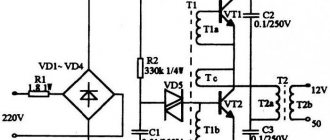
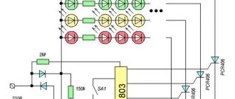
Electronic ballasts are an electronic board filled with electronic components. The circuit diagram of the connection (Fig. 1) and one of the options for the ballast circuit (Fig. 2) are shown in the figures.
Fluorescent lamp, C1 and C2 – capacitors
Electrical diagram of electronic ballasts
Electronic ballasts can have different circuit designs depending on the components used. The voltage is rectified by diodes VD4–VD7 and then filtered by capacitor C1. After voltage is applied, capacitor C4 begins charging. At a level of 30 V, dinistor CD1 breaks through and transistor T2 opens, then the self-oscillator on transistors T1, T2 and transformer TR1 is switched on. The resonant frequency of the series circuit of capacitors C2, C3, inductor L1 and generator are close in value (45–50 kHz). The resonance mode is necessary for stable operation of the circuit. When the voltage on capacitor C3 reaches the starting value, the lamp lights up. At the same time, the regulating frequency of the generator and voltage are reduced, and the inductor limits the current.
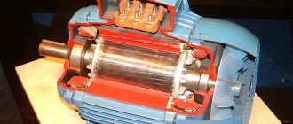
Photo of the internal structure of the electronic ballast
Photo of a typical electronic ballast device
Possibility of starting with burnt-out equipment
Repairing fluorescent lamps also has its own little tricks. For example, there was an urgent need to start such a lighting device, but the starter was faulty, and there was no way to replace it. This circuit element itself serves to heat the filaments in the fluorescent tube.
Well, what if, for example, the throttle fails? Nowadays you can’t find it in all stores.
Throttleless activation
It is quite possible to prolong the operation of a burnt-out light fixture. There is a way in which you can turn on a fluorescent fluorescent lamp without a throttle and starter (connection diagram in the figure). Of course, this method is not suitable for everyone; you need to have at least a little understanding of electrical engineering.
Throttleless switching circuit
Voltage is supplied after a short circuit of the filaments. The rectified voltage doubles, which is quite enough to start the lamp (in theory, this function is performed by the inductor). Capacitors C1 and C2 (in the diagram) must be selected for 600 V, and C3 and C4 - with a rated voltage of 1,000 V. After some time, mercury vapor, of course, will settle in the area of one of the electrodes, and the light from the lamp will become much less bright. It will be possible to get rid of this simply by changing the polarity, i.e. simply by deploying the reanimated burnt-out LL.
Starterless inclusion
There are lighting devices that are designed exclusively for operation without a starter. Such lamps are marked RS. If such a tube is installed in a lamp equipped with a breaker, the lamp burns out very quickly. This happens due to the need for more time to warm up the spirals of such fluorescent tubes. The starter's durability is short, it often burns out, and therefore it makes sense to consider the possibility of how to turn on a fluorescent lamp without it. To do this, you will need to install secondary transformer windings. If you remember this information, then the question will no longer arise of how to light a fluorescent lamp if the starter burns out (connection diagram below).
Thus, without extra costs, you can even assemble a fluorescent lamp with your own hands.
Connection diagram without throttle and starter
How to check electronic ballast for fluorescent lamps?
If in a dark room, when the light source is turned on, a barely noticeable glow of the filaments is observed, then failure of the electronic ballast device is likely, as well as breakdown of the capacitor.
The standard circuit of all lighting devices is almost identical, but may have significant differences, so at the first stage of testing you need to decide on the type of electronic ballast.
Ballast check
The test begins with dismantling the tube, after which it is necessary to short-circuit the leads with the filaments and connect a traditional 220V lamp with low power ratings. Diagnostics of the device in a professional repair shop is carried out using an oscilloscope, frequency generator and other necessary measuring instruments.
Self-checking involves not only a visual inspection of the electronic board, but also a consistent search and identification of failed parts.
Budget ballast devices are characterized by the presence of quickly failing capacitors at 400V and 250V.
Electronic ballast repair
If it is not possible to quickly replace a failed electronic ballast, you can try to repair the ballast yourself. To do this, select the following sequence of actions to troubleshoot:
- First, check the integrity of the fuse. This breakdown often occurs due to overload (overvoltage) in the 220 volt network;
- Next, a visual inspection of electronic components is carried out: diodes, resistors, transistors, capacitors, transformers, chokes;
- If characteristic blackening of a part or board is detected, repairs are made by replacing it with a serviceable element. How to check a faulty diode or transistor with your own hands, having a regular multimeter, is well known to any user with a technical education;
- It may turn out that the cost of replacement parts will be higher or comparable to the cost of a new electronic ballast. In this case, it is better not to waste time on repairs, but to choose a replacement that is similar in parameters.
General operating principle of the element
Essentially, the ballast for fluorescent lamps is a choke. It regulates the amount of current supplied by limiting or separating different frequency electrical signals. Eliminates DC ripple. The cathodes of fluorescent lamps are heated.
Next, they are supplied with the required amount of voltage, which activates the operation of the lighting device. The voltage is adjusted using a special regulator, which is soldered into the inverter circuit. It is he who adjusts the voltage range. Due to the above-mentioned features of the ballast, flickering in the light source is completely eliminated.
A starter is also built into the circuit. Its functions are voltage transmission and ignition. When the lamp is turned on, the current on the ballast chip decreases. This feature allows you to set the required operating mode of the lighting device.
Today, the following types of ballast devices are widely represented on the market:
- electromagnetic;
- electronic;
- ballasts for compact lamps.
The presented categories are marked by reliable operation and ensure long-term operation and ease of operation of all fluorescent lamps. All of these devices have identical operating principles, but differ in some respects.
Electromagnetic
These ballasts are suitable for lamps connected to the mains using a starter. The initially occurring discharge intensively heats up and short-circuits the bimetallic electrode elements. There is a sharp increase in operating current.
Electromagnetic ballast is easy to recognize by its appearance. The design is more massive compared to the electronic prototype.
When the starter fails, a false start occurs in the electromagnetic ballast circuit. When power is supplied, the lamp begins to blink, subsequently there is a smooth supply of electricity. This feature significantly reduces the working life of the lighting source.
| pros | Minuses |
| High-quality level of reliability, proven by practice and time. | Long startup - at the first stage of operation, startup takes 2-3 seconds and up to 8 seconds by the end of the service life. |
| Simplicity of design. | Increased energy consumption. |
| Ease of use of the module. | Lamp flicker at 50 Hz (strobe effect). It has a negative effect on a person who stays in a room with this type of lighting for a long time. |
| Affordable price for consumers. | The hum of the throttle is heard. |
| Number of manufacturing companies. | Significant weight of the structure and bulkiness. |
Electronic
Today, magnetic and electronic ballasts are used, which consist in the first case of a microcircuit, transistors, dinistors and diodes, and in the second case of metal plates and copper wire. By means of a starter, the lamps are started, and the phenomenon is organized in the electronic version of the part as a single function of this element with the ballast in one circuit.
- light weight and compactness;
- smooth fast start;
- unlike electromagnetic structures that require a 50 Hz network to operate, high-frequency magnetic analogues operate without noise from vibration and flicker;
- heating losses are reduced;
- power factors in electronic circuits reach 0.95;
- Extended service life and safety of use are ensured by several types of protection.
| Advantages | Flaws |
| Automatic ballast adjustment for different types of lamps. | Higher cost compared to electromagnetic models. |
| Instant switching on of the lighting device, without additional load on the device. | |
| Saving energy consumption up to 30%. | |
| Heating of the electronic module is excluded. | |
| Smooth light output and absence of noise effects during the lighting process. | |
| Increasing the service life of fluorescent lamps. | |
| Additional protection guarantees an increase in fire safety. | |
| Reducing risks during operation. | |
| An even supply of light flux eliminates rapid fatigue. | |
| Absence of negative functions in low temperature conditions. | |
| Compact and lightweight design. |
For compact fluorescent lamps
Compact types of fluorescent lamps are represented by devices similar to incandescent lamps of types E27, E40 and E14. In such schemes, electronic ballasts are built inside the cartridge. In this design, repairs in case of breakdown are excluded. It will be cheaper and more practical to purchase a new lamp.
Advantages and disadvantages.
To summarize, we can say that, like any electronic product, an electronic starter has advantages and disadvantages.
pros
- Longer service life.
- Greater efficiency, lower losses (at least, there is no constant magnetization reversal of the inductor core). Savings up to 30 percent.
- There are no reactive emissions into the power supply network. Do not interfere with other equipment.
- No flickering at start-up or strobe effect during operation.
- The automation turns off when the lamp fails.
- Smooth heating of the electrodes.
- Stable luminous flux during power surges.
- Possibility of operation on direct current (not all models).
- Have short circuit protection.
- No characteristic noise.
- It is possible to start the lamps at low ambient temperatures.
Minuses
- Low-quality, cheap electronic ballasts are short-lived.
- The main disadvantage is the price (they pay for themselves over time).
- Some models are not compatible with LED analogues of fluorescent lamps.
Schematic diagram
This is a large part of this electronic ballast; the Chinese did not include the inductor and capacitor here.
Actually, a diagram faithfully copied from a printed circuit board. The rating of the electronic components that made it possible to do this was determined not only “by appearance,” but also using measurements, with preliminary desoldering of the components from the board. In the diagram, the resistor values are indicated in accordance with the color coding. Only with regard to the choke, I allowed myself not to unwind the existing one to determine the number of turns, but measured the resistance of the wound wire (1.5 Ohms with a diameter of 0.4 mm) - it worked.
First assembly on the circuit board. I carefully selected the component values, regardless of size and quantity, and was rewarded - the light bulb lit up the first time. Ferrite ring (10 x 6 x 4.5 mm) from an energy-saving light bulb, its magnetic permeability is unknown, the diameter of the wire of the coils wound on it is 0.3 mm (without insulation). The first start-up is mandatory through a 25 W incandescent light bulb. If it is on and the fluorescent one initially blinks and goes out, increase (gradually) the value of C4, when everything worked and nothing suspicious was found, and removed the incandescent lamp, then reduced its value to the original value.
To some extent, focusing on the printed circuit board of the original source, I drew a signet for the existing suitable case and electronic components.
I etched the scarf and assembled the diagram. I was already looking forward to the moment when I would be satisfied with myself and glad to be. But the circuit assembled on a printed circuit board refused to work. I had to delve into and select resistors and capacitors. At the time of installation of the electronic ballast at the site of operation, C4 had a capacity of 3n5, C5 - 7n5, R4 resistance of 6 Ohms, R5 - 8 Ohms, R7 - 13 Ohms.
The lamp “fit” not only into the design; the lamp, raised all the way up, made it possible to comfortably use the shelf inside the secretary niche. Babay made the “room” feel comfortable.
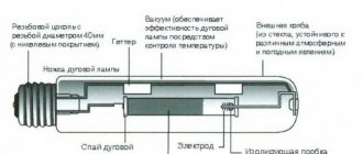
A fluorescent lamp (LL) is a glass tube filled with an inert gas (Ar, Ne, Kr) with the addition of a small amount of mercury. At the ends of the tube there are metal electrodes for applying voltage, the electric field of which leads to gas breakdown, the occurrence of a glow discharge and the appearance of electric current in the circuit. The glow of the gas discharge is pale blue and very weak in the visible light range.
But as a result of an electrical discharge, most of the energy passes into the invisible, ultraviolet range, the quanta of which, entering phosphorus-containing compounds (phosphor coatings), cause a glow in the visible region of the spectrum. By changing the chemical composition of the phosphor, different glow colors are obtained: for fluorescent lamps (FLLs) various shades of white have been developed, and for decorative lighting you can choose lamps of a different color. The invention and mass production of fluorescent lamps is a step forward compared to low-efficiency incandescent lamps.
Operating principle
Operating principle of fluorescent lamps
Let us briefly describe the interaction diagram between the starter, ballast and lamp:
- When power is applied, the current, passing through the ballast, passes through the starter contacts along the tungsten spirals, heating them and then goes towards zero
- The starter is equipped with a pair of contacts: movable and fixed. When current flows, the movable contact (bimetallic), heating up, changes its shape and connects with the first
- In this case, the current immediately increases significantly to the limit limited by the inductor. The electrodes are heating up
- The starter plate, on the contrary, begins to cool and disconnects the contacts. At this moment, a sharp surge in voltage occurs and electrons break through the gas. When mercury turns into vapor, the light source switches to operating mode
- The starter is no longer involved in the process - its contacts are open.
Perennial flowers (TOP 50 species): garden catalog for the garden with photos and names | Video + Reviews
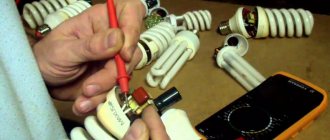
Checking fluorescent lamps
It is very simple to check the integrity of the tungsten filament; you need to take a regular tester that measures the resistance of the conductor, after which you need to touch the lead ends of the lamp with the probes. If the device shows, for example, a resistance of 9.9 ohms, then this will mean that the thread is intact. If, when checking a pair of electrodes, the tester shows a complete zero, this side has a break, so the fluorescent lamps will not turn on.
The spiral can break due to the fact that over the time of its use the thread becomes thinner, so the tension that passes through it gradually increases. Due to the fact that the voltage constantly increases, the starter fails, which can be seen by the characteristic “blinking” of these lamps. After the burnt out lamps and starters are replaced, the circuit will work without adjustments.
If, when you turn on the lamps, you hear extraneous sounds or notice a burning smell, then you must immediately turn off the power to the lamp and check the functionality of its elements. It may be that there is slack in the terminal connections themselves and the wire connection is warming up. In addition, if the inductor is of poor quality, a turn short circuit of the windings may occur, which will lead to failure of the lamps.
How to connect a fluorescent lamp?
Connecting a fluorescent lamp is a very simple process; its circuit is designed to ignite only one lamp. To connect a pair of fluorescent lamps, you need to slightly change the circuit, while acting on the same principle of sequential connection of elements.
In such a case, it is necessary to use a pair of starters, one per lamp. When connecting a pair of lamps to a single choke, it is necessary to take into account its rated power indicated on the housing. For example, if its power is 40 W, then it is possible to connect a pair of identical lamps to it, the maximum load of which is 20 W.
In addition, there is a fluorescent lamp connection that does not use starters. Thanks to the use of specialized electronic ballast devices, the lamp starts up instantly, without “blinking” the starter control circuits.
Connecting a fluorescent lamp to an electronic ballast
Connecting a lamp to electronic ballasts is very simple, because there is detailed information on their housing, and the connection of the lamp contacts with the corresponding terminals is also schematically shown. However, to make it more clear how to connect a fluorescent lamp to this device, you can simply carefully study the diagram.
The main advantage of this connection is the absence of additional elements that are needed for starter circuits that control the lamps. In addition, by simplifying the circuit, the reliability of the entire luminaire significantly increases, because additional connections to starters, which are quite unreliable devices, are eliminated.
Basically, all the wires that are needed to assemble the circuit come complete with the electronic ballast device itself, so there is no need to reinvent the wheel, come up with something and incur additional costs for purchasing the missing elements. In this video you can learn more about the principles of operation and connection of fluorescent lamps:
Post navigation
Electromagnetic or electronic ballast for fluorescent lamps is needed for the normal operation of this lighting source. The main task of the ballast is to convert direct voltage into alternating voltage. Each of them has its own pros and cons.
Typical ballast circuit
The electronic ballast design uses an active power factor correction, ensuring compatibility with the electrical network. The basis of the corrector is a powerful boost pulse converter controlled by a special integrated circuit. This provides rated operation with a power factor close to 0.98. The high value of this coefficient is maintained in any operating mode. Voltage changes are allowed in the range of 220 volts + 15%. The corrector ensures stable illumination even with significant changes in network voltage. To stabilize it, an intermediate DC circuit is used.
An important role is played by the mains filter, which smoothes out high-frequency ripples of the supply current. Together with the corrector, this device strictly regulates all components of the consumed current. The line filter input is equipped with a protective unit with a varistor and a fuse. This allows you to effectively eliminate network overvoltages. A thermistor having a negative temperature coefficient of resistance is connected in series with the fuse, which ensures that the input current surge is limited when the electronic ballast is connected from the inverter to the network.
In addition to the main elements, the ballast circuit for fluorescent lamps requires the presence of a special protection unit. With its help, the status of the lamps is monitored, as well as their shutdown in case of malfunction or absence. This device monitors the current consumed by the inverter and the voltage supplied to each lamp. If during a certain period of time the specified voltage or current level exceeds the set value, then the protection is triggered. The same thing happens during a load circuit break.
The executive element of the protective unit is a thyristor. Its open state is maintained by current passing through a resistor installed in the ballast. The value of the ballast resistance allows the thyristor current to maintain the on state until the supply voltage is removed from the electronic ballast.
The electronic ballast control unit is powered through a mains rectifier when current passes through the ballast resistor. Reducing the power of the electronic ballast and improving its efficiency allows the use of smoothing circuit current. This circuit connects to the point where the inverter transistors connect. Thus, the control system is powered. The construction of the circuit ensures that the control system is launched at the initial stage, after which the power circuit is started with a slight delay.
Troubleshooting procedure
Before looking for a breakdown, make sure there is voltage; perhaps its absence is the reason why the fluorescent lamp does not light up.
If this is not the reason, we look for it in this order. Replace the starter if:
- turn on the light and nothing happens;
- the bulb glows only at the edges;
- the light flashes with a strobe;
- The starter lights up, but the lamp does not start.
Please note that manufacturers recommend replacing fluorescent lamps and starters at the same time.
Replace the light bulb if:
- it flashes with a strobe light;
- the edges of the flask are black;
- it glows, but the brightness is not enough (it shines weakly);
- The lamp does not work.
A typical breakdown of budget lamps is the destruction of lamp holders and loss of contact. The high temperature of a closed lamp causes the destruction of plastic fastening elements and connectors. If possible, replace them, bend the contacts if the condition is satisfactory.
A possible malfunction is a burnt-out choke, often this breakdown is visible visually, a discolored, melted terminal.
If you really find a malfunction, to repair the lamp you will have to replace the choke with a working one. You can check the functionality with a multimeter; the resistance is good, about 30-40 ohms. Before placing a lamp in a non-working lamp, make sure that the choke is not closed. Otherwise, you will lose your worker too.
Sometimes wires break down - the vibration of the lamp breaks off a wire near the lamp holder or choke. In this case, repairing a fluorescent lamp comes down to restoring contact. Owners of old-style lamps were spared these faults.
If you have a lamp with electronic ballasts made in China and replacing the light bulb did not solve the problem, most likely the problem is in the electronic unit. In most cases, you can fix it yourself with a soldering iron and a multimeter at your disposal. Below we will go into detail on how to repair the electronic ballast of a fluorescent lamp with your own hands.
What's happened
Electronic ballast uses solid-state electronic circuitry to provide proper starting and operating electrical conditions to power HID light bulbs. They are often based on an SMPS topology, first rectifying the input power and then chopping it at a high frequency. Advanced EBs may allow brightness to be adjusted using pulse width modulation or by changing the frequency to a higher value. Ballasts incorporating a microcontroller or digital circuits can offer remote control and monitoring over networks or simple analog control using a 0-10 VDC dimming signal.
The use of electronic ballasts for HID lighting is becoming increasingly popular. Most new generation EBs can operate with both high pressure sodium (HPS) lamps and metal halide devices, reducing the costs of lighting systems that use both types of lamps. Initially the ballast acts as an arc starter by providing a high voltage pulse and then it functions as a limiter/regulator of the electrical flow within the circuit. EBs operate much cooler and easier than their magnetic counterparts.
Advantages and disadvantages
Thanks to advances in the technological features of electronic ballasts, these accessories have become widely used in fluorescent lamps (FL).
EB connection block
Important advantages:
- Flexible design and excellent control characteristics. There are different types of ballasts with adjustable functions that can operate the LL at different output levels. There are ballasts for low light and reduced energy consumption. For higher illuminance, high lumen output ballasts are available that can be used with fewer lamps and a higher power factor.
- Greater efficiency. Electronic throttles rarely generate much internal heat and are therefore considered more efficient. These EBs provide flicker-free and constant power fluorescent lamps, which is one of the most noticeable advantages.
- Less cooling load. Since the EBs do not include a coil and core, the heat generated is minimized and therefore the cooling load is reduced.
- Ability to operate more devices simultaneously. One EB can be used to control 4 lamps.
- Lighter in weight. Thanks to the use of electronic ballasts, the luminaires have less weight. Since it does not include a core and coil, it is comparatively light in weight.
- Less light bulb flickering. One of the greatest benefits of using these components is reducing this factor.
- Quiet operation. Another useful feature is that EBs operate quietly, unlike magnetic ballasts.
- Superior sensing capabilities - EBs have sensing capabilities as they detect the end of lamp life and turn off the lamp before it overheats and fails.
- Electronic throttles are available in a huge variety at many online electronics stores at affordable prices.
Disadvantages include the fact that with electronic ballasts, alternating currents can generate current peaks near voltage peaks, creating a high harmonic current. This is not only a problem for the lighting system, but can also cause additional problems such as stray magnetic fields, pipe corrosion, interference from radio and television equipment and even IT equipment failure.
High harmonic content also causes overloading of transformers and neutral conductors in three-phase systems. The higher flicker frequency may go unnoticed by the human eye, however, it causes problems with infrared remote controls used in home media devices such as televisions.
Additional Information! Electronic ballasts do not have circuitry to withstand power surges and overloads.
Main varieties
Today there are two types of ballast - electromagnetic and electronic. They differ in how they work, so it’s worth getting to know each of them.
Electromagnetic ballast
This type of implementation involves connecting the inductor in series to the lamp. Also, for the operation of electromagnetic ballasts, a starter is required, with the help of which the ignition process of the lamp is regulated. This part is a gas-discharge lamp, inside the bulb of which there are bimetallic electrodes.
The device works as follows:
- When voltage is applied to the starter, the bimetallic electrodes close due to heat. This leads to an increase in current strength, since it can only be limited by the internal resistance of the inductor windings.
- As the electric current increases, the electrodes of the fluorescent lamp begin to heat up.
- When the starter cools down, the bimetallic electrodes open.
- When the circuit is broken by the starter, a high voltage pulse occurs in the throttle coil, which leads to the ignition of the lighting device.
When the luminescent device returns to normal operation, the voltage on it and the starter is 50% less than the mains voltage, and this is not enough to trigger the second element. As a result, the starter goes into a disabled state and ceases to influence the operation of the lighting device.
Electromagnetic ballast is characterized by low cost and simple design. For a long time, these devices were actively used in the manufacture of lamps, but they have a number of disadvantages:
- It takes about 3 seconds for the luminescent device to enter operating mode.
- Lighting devices with electromagnetic ballast flicker during operation, which negatively affects the organs of vision.
- The energy consumption of these devices is significantly higher compared to electronic ballast.
- The throttle is noisy during operation.
Electronic implementation
Electronic devices are voltage converters that provide power to fluorescent lamps. Although many variations of electronic ballast have been created, most use a single block diagram. At the same time, manufacturers can make certain changes to it, for example, adding a brightness control circuit for a lighting fixture.
Transferring a fluorescent lamp lamp to normal operation using electronic ballasts is most often carried out in one of two ways:
- Before the ignition voltage is applied to the cathodes of the lamp, they are preheated. This allows you to get rid of flicker and also increase the efficiency of the lighting device.
- An oscillatory circuit is installed in the design of the lamp, which enters into resonance before a discharge appears in the lamp bulb.
Scheme of ballast for 36w lamps.
Why do you need ballasts?
Before we start talking about the throttle, let's figure out what ballasts are and what they are needed for. In order to answer these questions, it is necessary to understand how a fluorescent lamp (FLS) works. Let's take a look at its schematic representation.
In front of us is a glass flask in the form of a tube, into the ends of which two tungsten spirals are soldered - the anode and the cathode. The tube itself is filled with an inert gas with a small addition of mercury. If operating voltage is applied to the anode and cathode, the lamp will not light up - the resistance of the inert gas is too high, and there will be no current between the electrodes.
In order to start the device, it is necessary to warm up the coils. As soon as they warm up, thermionic emission begins, the same as in a conventional vacuum tube for radio receivers. Current will begin to flow between the electrodes, and mercury vapor will begin to emit ultraviolet light. When ultraviolet light hits the phosphor, it causes it to glow brightly. UV radiation itself is almost completely absorbed by glass and phosphor.
The start of the DLS is ensured by a special device - a starter, which briefly supplies voltage to the coils (we’ll talk about its switching circuit later). It is the starting part of the control gear.
Starters for launching DLS
You can make the lamp work (as they say, “start”) in another way, by briefly applying increased voltage to the electrodes. This is exactly how electronic ballasts work, which we’ll talk about later.
But after starting the LDS, new problems begin: the glow discharge in the bulb turns into an arc and instantly leads to a short circuit. To prevent this from happening, the current through the lamp must be limited during operation. This role is played by another device - electromagnetic ballast. It is the regulating part of the ballast equipment.
Electronic ballasts for LDS with a power of 36 W
Thus, without a starter the lamp will not start, without ballast it will burn out. The complex of these two devices is called ballast control. Now, I think you understand why ballasts are needed, and that you can’t do without them.
Important! The power of the choke must match the power of the lamp. Otherwise, the lamp will either go out immediately, or will not start at all, or will burn out.
Electronic circuits
Depending on the type of a particular light bulb, electronic ballast elements may have different implementations, both in electronic filling and in built-in features. Below we will consider several options for devices with different power and design.
Electronic ballast circuit for fluorescent lamps with a power of 36 W
Depending on the electronic parts used, the type and technical characteristics of the ballasts may differ significantly in the electrical circuit, but the functions they perform will be the same.
In the above figure, the circuit uses the following elements:
- diodes VD4–VD7 are designed for current rectification;
- capacitor C1 is designed to filter the current passing through the diode system 4-7;
- capacitor C4 begins charging after voltage is applied;
- dinistor CD1 breaks through when the voltage reaches 30 V;
- transistor T2 opens after breaking through 1 dinistor;
- transformer TR1 and transistors T1, T2 are started as a result of activation of the autogenerator on them;
- the generator, inductor L1 and series capacitors C2, C3 begin to resonate at a frequency of approximately 45–50 kHz;
- capacitor C3 turns on the lamp after it reaches the starting charge value.
Electronic ballast circuit based on a diode bridge for LDS with a power of 36 W
The above circuit has one feature - the oscillatory circuit is built into the design of the lighting device itself, which ensures resonance of the device until a discharge appears in the bulb.
Thus, the filament of the lamp will act as part of the circuit, which at the moment of the appearance of a discharge in a gaseous medium is accompanied by a change in the corresponding parameters in the oscillatory circuit. This takes it out of resonance, which is accompanied by a decrease in voltage to the operating level.
Electronic ballast circuit for LDS with a power of 18 W
Lamps that are equipped with E27 and E14 bases are most widespread among consumers today. In this device, the ballast is built directly into the structure of the device. The corresponding diagram is shown above.
Electronic ballast circuit based on a diode bridge for LDS with a power of 18 W
It is necessary to take into account the peculiarity of the structure of the self-oscillator, which is based on a pair of transistors.
Power is supplied from the step-up winding, indicated in diagram 1-1 of transformer Tr. Parts of the series oscillatory circuit are inductor L1 and capacitor C2, the resonant frequency of which is significantly different from that generated by the self-oscillator. The above diagram is used for budget class table lighting fixtures.
Electronic ballast circuit in more expensive devices for LDS with a power of 21 W
It should be noted that simpler ballast circuits, which are used for LDS-type lighting devices, cannot guarantee long-term operation of the lamp, since they are subject to heavy loads.
For expensive products, such a circuit ensures stable operation throughout the entire service life, since all elements used meet more stringent technical requirements.
Energy-saving lamp: repair with step-by-step photographs
After getting acquainted with the design, we can conclude that a breakdown can occur in one of two places:
- inside the flask;
- or in an electrical diagram.
In reality, the only way to find a fault is to conduct an internal inspection.
How to disassemble energy-saving lamps: tips for beginners
I will describe and show with photographs my personal experience. I admit that some products may have differences.
The lamp body consists of two detachable parts. The gap between them is barely noticeable. It can be filled with sealant or without it. This can be determined with a thin, sharp blade. For example, a stationery knife.
Initially I had to cut a layer of filler around the circumference. But the thin blade began to bend strongly under the applied bending force.
Then I took an electrician's knife. Its thick blade is adapted to work even with metals. He carefully began to push the resulting gap in opposite directions.
On one side I even had to trim off the remaining glue. He worked very carefully. You can easily push through the plastic and damage the case. Then additional problems will arise.
When you push the gap apart with a knife or a thin screwdriver, the engagement of the upper and lower parts is disconnected: the protrusions are squeezed out of the grooves.
You can see them better in the next photo.
This is what two built-in boards look like, connected to each other by wires.
The surge protector board with a rectifier is connected by wires to the base and the converter.
It is closed from below with a lid in the form of a dielectric base with latches.
It prevents the two boards from touching each other, protects against short circuits, and provides a gap for heat dissipation through natural ventilation.
After you have managed to disassemble the energy-saving lamp, immediately conduct an internal inspection of all its parts. Pay attention to blackening, charring, and other damage.
In my case, the boards themselves were clean, there were no traces of carbon deposits on them.
The paths were also in working order. The soldering of the radio components is done normally, no obvious defects are visible.
Since a visual inspection of the electronic components did not reveal any damage, then the flask should be inspected further.
Repairing a broken filament: 2 available methods
The first quick glance at the output of the filaments showed damage to the insulation, burnout of part of the filler from increased heat.
The interesting thing is that the copper wires of the incandescent filament leads are simply wound onto the pins of the board. There is no soldering. The copper metal has turned black and is covered with a layer of oxides.
This is an indirect sign of damage to the filaments. We can immediately conclude that large currents passed through them, and the heat removal was clearly not sufficient. One of the reasons for heating is the increased resistance of the contacts due to the lack of soldering.
Next, it is necessary to determine the serviceability of the electrodes, their ability to cause electronic emission and perform a hot start of the energy saver. This can only be done by electrical measurements, and you need to prepare for them.
It will be necessary to disassemble the heating circuit of the filaments to check their integrity. This is convenient to do with tweezers.
The open circuit looks like this:
To perform an electrical test, it is enough for us to unwind and separate only one wire, and I do not recommend touching the second one yet.
I show the board diagram prepared for measurement in the photo below. The insulation burns are clearly visible on it.
Next, we simply take a digital multimeter or a regular tester and use it to measure the electrical resistance of the threads.
In this way, I discovered that on one side of the bulb the filament of the lamp was burnt out and torn, and on the opposite side it was intact. I marked them for memory with a ballpoint pen and restored the winding of the disconnected wires with the same tweezers.
Next you will have to choose a method for repairing and starting the energy-saving lamp using one of two options:
- using the hot method with careful ignition of the remaining filament;
- in a quick, cold way.
I chose the first one. I describe it at the beginning.
Gentle repair of an energy-saving lamp bulb
There are no tricks here. You just need to take into account the electrical resistance of the filament. Usually it is somewhere in the range of 4÷5 Ohms. You will need to select the same resistor.
I went through one box. It wasn’t in it, and it was too lazy to dig through the rest of the stock. I decided to show a way out of this situation. Soldered the composite structure. For clarity, I made it long.
The result is such a funny diagram: it is quite suitable for understanding the technology of repairing a lamp, but in real life you will need to find a normal resistor. It is not difficult. By the way, it must be selected according to the power of at least a watt, and preferably 2.
For clarity, I tied this composite resistance with wires to the legs of the broken thread: I bridged the broken contact with it. The base was screwed into the table lamp socket (the lampshade was removed - see the photo above).
I apply voltage to the assembled circuit and see a glowing working light.
All that remains is to select a normal resistor, solder it in place of the composite one and assemble everything in reverse order inside the dielectric housing.
I think that special knowledge is not required here. With that, I move on to explaining how to repair the bulb using the second method.
Conclusion: replacing a broken filament with a shunt resistor in an energy-saving and fluorescent lamp restores the broken circuit of the starting current passing through the starter or electronic ballast.
Cold start circuit for an energy-saving lamp with a broken filament
In this situation, a gas discharge inside the flask is created by a banal increase in the voltage between the electrodes by connecting a multiplier of diodes and capacitors.
The stationary electronic ballast circuit is removed from work. If it is working properly, then it can be used to connect to other flasks using the hot start principle. Just pay attention to the correspondence between the power of the block and the light source.
During a cold start, the entire filament will be subjected to extreme stress. It is difficult to calculate how long it will last. Therefore, I recommend immediately bridging both at all ends of the glass flask.
The multiplier raises the voltage value to kilovolts. In principle, household wiring is designed for this value. For insulation, this danger is not particularly critical, and a person is exposed to an increased risk of injury from exposure to electric current.
From personal experience: using a cold start scheme, about ten years ago I restored the functionality of a pair of fluorescent lamps. They are still shining.
To start burnt-out energy-saving lamps using this scheme, it is necessary to take into account the dimensions of the resulting voltage multiplier. It is likely that it will not fit in the base housing even with the electronic ballast removed.
In this situation, you will have to make an external housing for it and connect the lamp through additional connectors. Therefore, immediately estimate the dimensions of the resulting multiplier and the place for it inside the base of the flask.
Electronic ballast repair: what to look for
The easiest way to check the serviceability of ballasts is to connect it to a bulb with intact filaments and apply an input voltage of 220. If the lamp lights up, then the electronic ballast is working. Otherwise, you need to look for faults.
Usually, the owner buys not one, but several identical lamps from the store to organize lighting. When they fail, they should not be thrown away, but the cause of the failure should be checked.
Quite often you can assemble one serviceable one out of two damaged ones. There will still be spare parts that will also come into use over time.
I outlined the principles of constructing circuits for pulse converters and the main types of their designs in a separate article for novice craftsmen. I recommend checking it out. Many provisions will be useful when troubleshooting problems that arise.
When repairing electronic ballast equipment, it is necessary to follow the same sequence of actions as for the UPS.
I show a typical circuit of electronic ballasts in the picture below. For some designs it may differ slightly, but the algorithm of actions for checking the elements remains virtually unchanged.
Fuse FU1 is in the 220 volt supply circuit and works together with resistor R1 (1÷30 Ohm) to the rectifier bridge VD1÷VD4 (TN4005). Diode VD5 is the same brand, and VD6 and VD7 are 1N4148.
Dinistor brand VS1 DB3. It may be absent in low power lamps. Transistors most often use MJE 13003.
Capacitance ratings: C1 and C3 - 0.1 µF; C2— 1.5÷10 µF (400V); C4 - 0.033÷0.1 µF (400V); C5 - 1800÷3900pF (650 V).
Chokes L1 and L2 are designed to dampen interference of high-frequency signals, preventing their output into household lighting wiring.
Installation of electronic ballasts can be done in various ways.
First of all, when inspecting the electronic ballast board, attention is paid to the condition of the fuse, electrolytic capacitors and the serviceability of the diodes. Any deviations in the geometric shape and blackening of the body indicate a high probability of damage.
Don’t forget to turn the printed circuit board over and visually evaluate the condition of the traces and soldered parts.
Checking the fuse
It is always placed at the entrance to the electronic ballast, it can be placed in series with the current-limiting resistor R1 and even closed with one housing. There was a design made directly on the track by reducing its cross-section.
The role of the fuse can be assigned to the low-resistance input resistance. There are many options. We need to figure it out specifically.
The integrity of the fuse is determined by measuring its electrical resistance or by ordinary continuity testing. In case of breakdown, it must be replaced. Immediately evaluate the design of the new one and its connection capabilities.
However, I remind you that it does not burn out that easily. This means: there was an overload or short circuit in the protected circuit: checking all electronic components is required.
Diode check
Their integrity is also determined by continuity, but measurements are performed on both sides of the semiconductor junction. In one case, a working diode should pass current, and in the other, block it.
When checking diodes soldered to the board, there may be continuity errors due to the connection of parallel circuits: you will need to unsolder it at least from one end and break the circuit.
If you place half a blade from a safety razor under the heated part, the process can be made easier.
Checking capacitors
Suspicious containers are removed from the board and their size is measured with a multimeter. If it is not available, you can use a pointer tester. I showed the technique in an article about repairing switching power supplies.
Checking transistors
The MJE 13003 series has one very interesting feature. These bipolar transistors are available in one package in three modifications:
- ordinary;
- with built-in diode;
- compound.
It’s difficult to say offhand what is in your electronic ballast and how it works. It is necessary to understand.
It is impossible to visually distinguish them except by the small markings of the last three characters. Therefore, it is better to call the internal circuit. In the picture below I show the principle of assembling a composite transistor. Be careful.
The transistors of the 13003 series must be checked with a multimeter in resistance measurement mode in all positions between the terminals of the legs and then analyzed the results obtained.
After checking all electronic ballast parts and replacing faulty ones, the functionality of the luminaire under voltage is checked. And here you need to be very careful, you shouldn’t joke with electricity.
Connection diagrams for fluorescent lamps using EMF
EMPRA is an electromagnetic ballast, and in fact, an ordinary choke. In the circuit diagram for connecting the EMGR, a starter is required, which creates the first impulse to start the fluorescent lamp to glow.
Read, electronic ballasts and emballasts. What are the differences between ballasts
Connection diagram for a fluorescent lamp EMPRA
This connection diagram is used in most standard single-lamp local lighting luminaires of economy class.
Circuit inductive implementation
- Supply voltage 220 Volts;
- The inductor (LL) is connected in series to the power wire and lamp terminal 1;
- The starter is connected in parallel to terminals 2 and 3 of the lamp;
- Pin 4 of the lamp is connected to the second power wire;
- The circuit involves a capacitor, which reduces the voltage pulse, increases the service life of the starter and reduces radio interference when the lamp is operating.
Circuit inductive-capacitive implementation
The second connection circuit is called inductive-capacitive. In it, the inductor and capacitor (inductive and capacitive reactance of the circuit) are connected in series. The starter is still connected in parallel with the output of lamp 2-3.
Connection diagram for 2 fluorescent lamps up to 18 W (EMP)
The connection diagrams change slightly with two lamps. The most common two circuits are for lamps up to 18 W (series) and lamps 36 W (parallel).
In the first scheme, two starters are still involved, one starter for each lamp. The inductor is connected as in an inductive circuit. The power of the choke is selected by summing the power of the lamps.
Important! In this (series) circuit, it is necessary to use 127 (110-130) Volt starters. Lamp power cannot be more than 22 W
In the second parallel circuit, two chokes (LL1 and LL2) are already involved. There are still two starters, one starter for each lamp.
Important! This circuit uses 220-240 Volt starters. Lamp power up to 80 W
Important note. Modern electronic ballasts are produced in a single housing
For connection, there are only contact pins on the case. The lamp connection diagram is indicated on the housing.
Design and principle of operation of electronic ballasts
Any electronic ballast consists of the following elements:
- device for current rectification;
- electromagnetic radiation filter;
- circuit power factor correction unit;
- voltage smoothing filter;
- inverter;
- choke or ballast for lamps.
The structure can be pavement or half-bridge. The first option has improved characteristics and is used in high-power lamps, from 100 W. The circuit effectively maintains the glow indicators and the voltage supplied to the cathodes.
Half-bridge circuits are more popular because Suitable for most household fluorescent lamps up to 50 W. Designs marked 2x36 support the connection of two 36 V lamps.
The operation of the device consists of the following steps:
- Turning on and preheating the filaments. This is an important manipulation that significantly extends the life of lighting sources. Without preheating, the lamp will not turn on at low temperatures.
- Generation of a high-voltage impedance pulse with a voltage of about 1.5 kV, which causes a breakdown of the gaseous medium inside the flask and starts the glow.
- Stabilize voltage and maintain it at the required level. The voltage to support combustion is low, which makes the circuit safe.
Operating principle of electronic ballast
The action of electronic ballasts is directly related to the operating principle of the fluorescent lamp itself. The main stage is its launch, during which certain conditions must be met. First of all, both filaments are heated, after which they are supplied with high voltage, about 600 volts. The value of the ignition voltage is directly dependent on the length of the glass tube. The shorter the lamp and the lower its wattage, the lower the required starting voltage will be.
At the initial stage, the input mains voltage is rectified to a constant value within 260-270 V and its subsequent smoothing using an electrolytic capacitor C1. This is clearly visible in the diagram presented.
Then the work of a push-pull half-bridge converter begins, consisting of two high-voltage bipolar transistors with a p-p-p structure. These transistors perform the function of switches, and the entire circuit converts a direct voltage of 260-270 V into a voltage with a high frequency of up to 38 kHz. Due to this, the size and weight of the device are reduced.
The electronic ballast circuit includes a transformer that simultaneously performs load and control functions. Of its three windings, two four-turn windings are control windings, and one two-turn winding is working. The working winding included in the circuit creates the necessary load for the converter.
Initially, the converter is started using a symmetrical dinistor, which opens if the voltage exceeds the operating threshold at the connection points. When in the open state, it sends a pulse to the transistor base, which causes the converter to start. A capacitor located in the resonant circuit and connected directly to the lamp provides a voltage drop to the level at which the lamp lights up.
Thus, with the help of the maximum current, both filaments are heated, and the lamp is directly ignited due to the high resonant voltage on the capacitor. When the lamp is lit, the resistance decreases, but the remaining voltage resonance ensures its continued combustion. Current limitation occurs due to the inductance of the inductor. Despite such a detailed description, it actually takes less than 1 second to light a fluorescent lamp.
System health check
After connecting the fluorescent lamp, you should make sure that it is working and that the ballasts are in good working order. To carry out the tests, you will need a tester with which to check the cathode filaments. The permissible resistance level is 10 ohms.
If the tester determines the resistance to be infinite, it is not necessary to throw away the light bulb. This light source still retains functionality, but it must be used in cold start mode. In the normal state, the starter contacts are open, and its capacitor does not allow direct current to pass through. In other words, the ringing should show a very high resistance, which sometimes reaches hundreds of ohms.
After touching the choke terminals with the ohmmeter probes, the resistance gradually decreases to a constant value inherent in the winding (several tens of Ohms).
It is not possible to reliably determine the turn-to-turn short circuit in the inductor winding using a conventional ohmmeter. However, if the device has an inductance measurement function and data on electronic ballasts, a discrepancy between the values will indicate a problem.
Electronic ballast circuits 4×18 (2×36)
EB 4×18 is used with inverting capacitors with a capacity of 5 pF. Thus, the resistance of this module can increase to 40 Ohms. Another feature of this circuit is the location of the choke element (it can be found below the dinistor).
Electronic ballast circuit 4×18
The circuit above uses only one transistor. The transformer performs the function of reducing and rectifying the current. This element protects the device from overloads, but there is also a fuse in the circuit.
Scheme for "Navigator"
Another 4×18 EB is “Navigator”. The circuit also contains a step-down transformer and a transistor. The main difference is the presence of a special regulator that allows you to change the output voltage. The capacitive resistor also distinguishes this circuit from the previous one.
Note! Here two capacitors with a capacity of 5 and 7 pF are used. This allows you to create resistance up to 40 ohms
This circuit does not use a fuse.
Scheme 2x36
The 2x36 ballast circuit includes a transceiver for expansion. The device is connected using an adapter device. As in the previous versions, there are capacitors, but their capacitance is smaller, only 4 pF. The circuit is distinguished by the presence of thyristors and frequency regulators. For most models of modules of this type, you can see two rectifiers in the circuit. The operating voltage of such a ballast is 200 V, and the frequency is 55 Hz.
Electronic ballast 4x18 is a necessary device to maintain the integrity of fluorescent lamps. There are several schemes to connect it. You can choose the most suitable and easiest to implement.
How does LL work with electromagnetic ballast?
Pay attention to this connection diagram. Marking LL1 is a ballast
There is a gaseous environment inside fluorescent lamps. As the current increases, the voltage between the electrodes in the lamp gradually drops and the resistance is negative. The ballast is used precisely to limit the current, and also creates an increased short-term ignition voltage for the lamps, since there is not enough of it in a regular network. This element is also called a choke.
Such a device uses a starter - a small glow discharge lamp (E1). It contains two electrodes. One of them is bimetallic (movable).
In the initial position they are open. By closing contact SA1 and applying voltage to the circuit, the current does not initially pass through the light source, but a glow discharge appears in the starter between the two electrodes. The electrodes heat up, and the bimetallic plate bends as a result, closing the contact. The current passing through the ballast increases, heating the electrodes of the fluorescent lamp.
Next, the electrodes in the starter open. A process of self-induction occurs. The choke creates a high voltage pulse, which ignites the LL. The rated current passes through it, but then it drops by half due to a decrease in the voltage across the inductor. The starter electrodes remain in the open position as long as the light is on. And capacitors C2 and C1 increase efficiency and reduce reactive loads.
Connecting fluorescent lamps
Advantages of classic electromagnetic ballast:
- low cost;
- ease of use.
- noise of operating throttle;
- LL flicker;
- long lamp ignition;
- weight and large dimensions;
- up to 15% energy losses due to phase advance of alternating current voltage (power factor);
- poor activation in low temperature environments.
On a note! The problem of energy loss can be solved by connecting (in parallel to the network) a capacitor with a capacity of 3-5 μF.
How to choose the right one
Before choosing a device for lighting lamps, pay attention to the following characteristics:
Type, power and number of lamps in the lighting scheme. The specification sheet for an electronic fluorescent ballast will indicate what types and configurations of fixtures are designed to operate the ballast. Start type - instant or programmed. If the lighting system is subject to frequent switching due to occupancy sensors or other factors, select “programmed start.” Otherwise, "instant" is the best choice. Ballast factor. The usual ballast factor (0.77 to 1.1) is the default value for most general lighting. A low ballast factor (1.1) is useful when the goal is to increase light output for areas such as warehouses or large retail stores. In this case, the user will receive approximately a 10% increase in luminous flux compared to the nominal illumination of the device. Input voltage. Some EBs provide universal voltage, others specific voltage. In any case, check the input voltage requirements - 120/277/347 V. Minimum initial temperature. Ballast specification sheets include temperatures that will vary depending on the type of fixture being controlled by the ballast. For example, EB can show a minimum initial temperature from −17 C to +30 C. Obviously, the variations are quite significant. Therefore, when choosing an EB, they proceed from the minimum and maximum air temperatures in the room. The normal connection diagram is parallel. This allows other lights to remain lit even if one bulb in the fixture goes out. Anti-stratification control: Strata are unwanted bright and dim areas that can form a standing wave structure along the entire length of the fixture. Streaks are more likely to occur when the lamp is operated at low temperatures. Manufacturers have developed ways to minimize these areas and often refer to the anti-stripping feature in the EB specification. Sound rating. An EV with a rating of “A” will hum quietly, with a rating of “D” it will cause a pronounced noise
The importance of sound assessment depends on the purpose of the premises. In libraries, LLs with the quietest ballast are installed, while this parameter is not so important for warehouses. LED Transition: Some EV manufacturers have lists of instant and programmed starting ballasts that they call "LED Ready". Manufacturer's warranty.
The choke in the electronic ballast is faulty
Many malfunctions of fluorescent lamps are associated with the inductor contained in the electronic ballast circuit. Outwardly this manifests itself as follows:
- The lamp does not turn on at all.
- After switching on, a dim glow forms around the edges, but the device does not light up completely. The lamp may flash brightly and then no longer light.
- The flickering becomes clearly visible, and the glow itself is very dim.
- A luminous running stream may appear along the glass bulb, the surface is illuminated unevenly, etc.
- While the lamp glows, the blackness along the edges of the tubes becomes clearly visible.
The check should begin with the presence of mains voltage, which may be completely absent, for example, due to a break in the line. Then a visual inspection is carried out and the integrity of the spirals is checked. If they are broken, the lamp must be replaced. Next, the condition of the contacts in the cartridge is checked to determine the serviceability of the starter. If all elements are normal, you can proceed to checking the throttle.