Solution:
The activities were carried out in accordance with the PUE 7th ed. Chapter 1.7.
In accordance with PUE clauses 1.7.96, 1.7.97 and 1.7.104 for electrical installations with voltages above 1 kV in networks with an isolated neutral (35-10 kV), the resistance of the charger should not exceed 4 Ohms. In accordance with the PUE clause 1.7.101, the resistance of the grounding device to which the neutrals of a generator or transformer or the terminals of a single-phase current source are connected, at any time of the year should be no more than 4 Ohms at a line voltage of 380 V of a three-phase current source.
The set of measures to ensure the necessary requirements for the grounding device is represented by the following solutions:
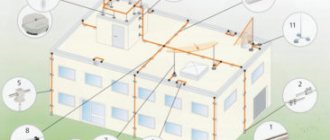
- installation of two vertical electrodes 10.5 m long and one vertical electrode 9 m long, united by a horizontal electrode made of a corrosion-resistant copper-plated steel strip with a cross-section of 30x4 mm. The depth of the strip is 0.5 m;
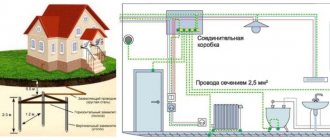
- A horizontal grounding conductor 3 meters long (copper-coated strip with a cross-section of 30x4 mm) is laid to the wall of the building.
The location of the grounding device elements is shown in Figure 1
Picture 1
Calculation of the resistance of the grounding device:
Horizontal electrode resistance:
where ρ – soil resistivity, Ohm m; b—width of the horizontal electrode strip, m; h is the depth of the horizontal grid, m; Lhor – length of the horizontal electrode, m.
Vertical electrode resistance:
where ρeq – equivalent soil resistivity, Ohm m; L – length of vertical electrode, m; d – diameter of the vertical electrode, m; T – depth – distance from the earth’s surface to the ground electrode, m;
where t is the depth of the top of the electrode, m
Grounding device impedance:
where n is the number of sets; kisp – utilization factor;
The calculated resistance of the grounding device is 3.68 Ohms.
List of required materials:
| No. | Rice | vendor code | Product | Qty |
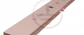
| 1 | ZZ-000-030 | ZANDZ Universal grounding kit (30 meters) | 1 | |
| 2 | GL-11075-20 | GALMAR Copper-plated strip (30*4 mm / S 120 mm²; coil 20 meters) | 1 | |
| 3 | GL-11075-10 | GALMAR Copper-plated strip (30*4 mm / S 120 mm²; coil 10 meters) | 1 |
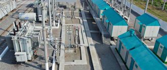
Grounding of substations Grounding of package transformer substations
Our company offers materials for grounding various types of substations. Basic regulatory references for grounding devices.
RULES FOR ELECTRICAL INSTALLATIONS, Seventh Edition Grounding devices of electrical installations with voltage up to 1 kV in networks with a solidly grounded neutral
"1.7.100. In electrical installations with a solidly grounded neutral, the neutral of a three-phase alternating current generator or transformer, the midpoint of a direct current source, one of the terminals of a single-phase current source must be connected to the grounding conductor using a grounding conductor. An artificial ground electrode designed to ground the neutral, as a rule, should be located near the generator or transformer. For intra-shop substations, it is allowed to place the ground electrode near the wall of the building.”
"1.7.101. The resistance of the grounding device to which the neutrals of a generator or transformer or the terminals of a single-phase current source are connected, at any time of the year should be no more than 2, 4 and 8 Ohms, respectively, at line voltages of 660, 380 and 220 V of a three-phase current source or 380, 220 and 127 In a single-phase current source."
"1.7.111. Artificial grounding conductors can be made of black or galvanized steel or copper."
Table 1.7.4
The smallest dimensions of grounding conductors and grounding conductors laid in the ground
| Material | Section profile | Diameter, mm | Cross-sectional area, mm | Wall thickness, mm |
| Black steel | Round: | |||
| for vertical grounding conductors | 16 | — | — | |
| for horizontal grounding conductors | 10 | — | — | |
| Rectangular | — | 100 | 4 | |
| Angular | — | 100 | 4 | |
| Pipe | 32 | — | 3,5 | |
| Galvanized steel | Round: | |||
| for vertical grounding conductors | 12 | — | — | |
| For horizontal grounding conductors | 10 | — | — | |
| Rectangular | — | 75 | 3 | |
| Pipe | 25 | — | 2 | |
| Copper | Round | 12 | — | — |
| Rectangular | — | 50 | 2 | |
| Pipe | 20 | — | 2 | |
| Multi-wire rope | 1,8* | 35 | — |
* Diameter of each wire.
We propose to consider the installation of a grounding device for PTS. The main material, also known as the vertical grounding conductor, is a steel rod coated with a layer of copper using an electrochemical method. The copper layer is at least 250 microns.
The rod is threaded on both sides.
The vertical ground electrode is driven into the ground. The length of one copper-plated rod is 1.2 meters. Using a brass coupling, the rods are mechanically connected, thus increasing the length (depth) of the ground electrode. This installation method and these materials are effective in limited installation conditions. This technology makes it possible to achieve current flow resistance in the range from 1 to 4 ohms.
To install the grounding of the KTP, 10 rods, 10 couplings, a tip for the first rod, and an impact-receiving head for transmitting the impact from the vibrating hammer to the rods were needed. The grounding conductor is a steel strip measuring 40x4 mm, galvanized 3 meters.
Tools: - jackhammer with attachment for driving rods; — SDS-MAX hammer drill with a drill with a diameter of 26 mm and a length of 1 meter; — angle grinder; - pipe wrenches; — wrenches 13; — 50 m extension cord for powering power tools.
The first thing required is to determine the installation location. It is necessary to make sure that there are no communications, power cables or any building structures (concrete foundations) passing through this area.
Using an SDS-MAX hammer drill and a drill with a diameter of 26 mm, we go through the asphalt layer and gravel substrate.
Let's assemble the first rod. We screw the driving tip onto one side and onto the second coupling. We screw the shock-receiving head into the coupling. We insert the assembled rod into the drilled hole.
To hammer in vertical rods we use a jackhammer with an impact force of 20 J and an SDS-MAX adapter. With the other end we insert the nozzle into the shock-receiving head.
We hammer in the first rod so that the coupling is higher than the hole in the asphalt. Unscrew the impact head. Fill with conductive liquid. Install the next rod. We screw the rod into the coupling, holding it with a pipe wrench. Tightening is carried out until a characteristic creak occurs. We install the impact-receiving head on the upper end and continue hammering.
The first few rods are usually driven in with some ease, because... The top layer of soil is not so dense. We hammer in all the rods, leaving 15 cm at the last one for connecting the clamp. The clamp is made of stainless steel and is tightened with 4 bolts.
10 rods for this PTS gave 3.37 ohms, which satisfies the requirements.
Next, you need to connect the grounding conductor to the vertical ground electrode through the clamp. As a result, the entire connection is wrapped with a special insulating tape, which will form an insulated cocoon to protect it from water and dirt.
The time spent on the entire installation of the KTP grounding device was 1.5 hours, taking into account electrical measurements and connection to the KTP GZSh. The cost of such a kit was 15 thousand rubles.
This installation method and original materials are applicable in particular to substations for various purposes, because There is not always space to install a large circuit with several grounding electrodes.
Substation grounding device
Grounding is an intentional electrical connection of any point in the network, electrical installation or equipment with a grounding device [4].
Three types of grounding are required at the substation: protective; working; lightning protection.
Protective grounding is grounding performed for electrical safety purposes [4].
Working grounding is the grounding of a point or points of live parts of an electrical installation, necessary to ensure the operation of the electrical installation (not for electrical safety purposes) [4].
Lightning protection grounding is necessary to ensure effective protection of electrical installations from lightning surges. Lightning protection grounding includes grounding of lightning rods, arresters, cables, roofs of indoor switchgear, etc.
For all three types of grounding, the same grounding device can be used, but it is selected according to the most stringent requirements, i.e. at the lowest permissible value.
For working and protective grounding, a common ground electrode is usually used. Moreover, protective grounding usually has the most stringent requirements.
Working grounding depends on the neutral mode. The neutral mode up to 1 kV is determined only by safety requirements. There may be an isolated neutral or solidly grounded one.
The neutral mode above 1 kV is determined by the following requirements:
1) safety precautions;
2) permissible single-phase fault current;
3) overvoltages arising in such modes;
4) reliability of relay protection;
5) operating voltage of undamaged phases in relation to ground.
In Russia, the following neutral modes are used:
∙ 6 kV – isolated (maybe with capacitive current compensation);
∙ 10 kV – isolated (maybe with compensation);
∙ 35 kV – with compensation (can be isolated);
∙ 110 kV – effectively grounded;
∙ 220 kV and above – solidly grounded.
The purpose of protective grounding is to reduce touch and step voltage to a safe value.
The calculation of the protective grounding of a substation can be carried out based on the permissible resistance to the spreading of the grounding current or based on the permissible touch voltage .
Calculation of the grounding device of a substation in areas with high soil resistivity, including in permafrost areas, is recommended to be carried out in compliance with the requirements for touch voltage [4]. In other cases, it is recommended to carry out the calculation according to the permissible soil resistance.
The resistance value RЗ of the grounding device for each substation voltage class is selected according to the PUE:
1) in electrical installations with voltages above 1 kV, in networks with an effectively grounded neutral
RЗ £ 0.5 Ohm;
2) in electrical installations with voltages above 1 kV, in networks with an isolated neutral and compensation for capacitive currents
RЗ £, but not more than 10 Ohm,
where IЗ is the calculated ground fault current;
3) in electrical installations up to 1 kV with a solidly grounded neutral, the resistance of the grounding device should be no more than 2, 4 and 8 Ohms, in networks with line voltage 660, 380 and 220 V, respectively;
4) in electrical installations up to 1 kV with an isolated neutral, the resistance of the grounding device must be
RЗ £, but not more than 4 Ohms.
The fault current in formulas for networks with an isolated neutral can be determined using the approximate formula
;
where Un – linear network voltage, kV, lк
and
lв
– total length of electrically interconnected cable and overhead lines, km.
In networks with compensation of capacitive currents, the following should be taken as the calculated current:
a) current equal to 125% of the rated current of the most powerful of these devices (for grounding devices to which compensating devices are connected);
b) the residual ground fault current passing in a given network when the most powerful of the compensating devices is disconnected (for grounding devices to which compensating devices are not connected).
The protective resistance is calculated for both voltage classes used at the substation. The smallest resistance is taken as the calculated resistance of the substation.
To calculate protective resistance, two main engineering methods are used: 1) utilization factors ; 2) induced potentials.
The utilization coefficient method is used for both simple and complex designs of group grounding conductors. In this case, the soil is considered as homogeneous and only for the top layer of soil freezing or drying of the soil is taken into account. In reality, the earth is not homogeneous, but has a complex structure.
In the second method, a two-layer earth model is adopted with different resistivities of the lower and upper layers of the soil. This method is more labor-intensive and requires additional information about the composition and resistivity of the soil, but it gives more accurate results.
For educational purposes, when there is no exact data, the first method is usually used.
Grounding electrodes are divided into natural and artificial . To reduce the cost of grounding devices, first of all, you need to use natural grounding electrodes. It is recommended to use water pipes, pipelines (with the exception of oil and gas pipelines), metal and reinforced concrete structures of buildings and structures, lead cable sheaths (aluminum are not allowed) as natural grounding conductors.
If the resistance of natural grounding electrodes is not enough, then artificial grounding electrodes are used.
Artificial grounding electrodes are metal electrodes buried in the ground specifically for the construction of grounding electrodes. They consist of vertical electrodes connected to each other by a horizontal electrode laid to a depth of 0.5−0.7 m.
Rods, pipes and angles can be used as vertical electrodes. They have minimum acceptable dimensions: a rod made of black steel has a diameter of at least 18 mm, and a rod made of galvanized steel has a diameter of at least 16 mm.
As a horizontal electrode, you can use: a strip with a cross-section of at least 150 mm2 (usually 5-40 mm2 is taken) or a rod with a diameter of 12 mm (both black and galvanized steel).
Depending on their location, grounding electrodes are divided into two types: remote and contour. A loop grounding device is placed along the contour (perimeter) of the site on which the equipment to be grounded is located, as well as inside this site, which is why it is also called distributed. For educational purposes, we consider only the contour ground electrode (Fig. 1.5).
a) b)
Rice. 1.5. Loop grounding conductor of closed a) and open b) substations: 1 – vertical electrodes; 2 – horizontal electrode;
3 – fence; 4 – leveling grid
To equalize the potential on the earth's surface in order to reduce touch voltage and step voltage, leveling grids are used. In open substations, it is recommended to lay grids at a depth of 0.5 - 0.7 m with a cell size of 6 -12 m. The grid resistance is not taken into account in the calculations , providing an additional (backup) reduction in resistance.