clause 2.3.24. Each cable line must have its own number or name. If a cable line consists of several parallel cables, then each of them must have the same number with the addition of the letters A, B, C, etc. Openly laid cables, as well as all cable terminations, must be equipped with tags indicating on the tags of cables and terminations the brand, voltage, cross-section, number or name of the line; on the coupling tags - coupling numbers and installation dates. Tags must be resistant to environmental influences. On cables laid in cable structures, tags must be located along the length at least every 50 m.
6.3.2 Installation of electrical wiring on cable trays and cable ladders, in cable and special cable boxes
6.3.2.11 Conductors laid in boxes and on trays must be marked at the beginning and end of the routes of trays and boxes within one room, open installation or structure , as well as at the places where they are connected to electrical equipment. Cables must also be marked at route turns and branches. 6.3.6 Laying wires and cables in steel pipes 6.3.6.12 At the end points of the wiring, wires and cables must be marked in accordance with the design. 6.3.8 Installation of auxiliary circuits 6.3.8.3 The devices should be marked before installing the auxiliary circuit wires according to the electrical connection diagram. If installation is complicated, then, as an exception, devices can be marked after installation is completed. The wires of the auxiliary circuits should not cover the marking areas of the devices. 6.3.8.11 Wires and cores of control cables connected to assemblies (rows) of clamps must be marked according to the diagrams. Control cables must be marked at the ends, in places of branching and intersection of cable flows, when passing through walls, ceilings, etc. The ends of the free conductors of control cables must be insulated. 6.3.8.14 The tag is fixed on the cable below the cutting at a distance of no more than 50 mm using mounting tape or ties (clamps). The distance from the cable bandage to the tag should be no more than 20 mm. It is recommended to print inscriptions on cable tags and on PVC pipes using a cable printer. 6.3.8.15 The inscriptions on the PVC tag of each cable must contain on the front side: - cable number; — cabinet number at the beginning of the cable; — number of the cable end cabinet; on the reverse side: - cable type; — number of cable cores; — cross-section of cable cores; - length of cable. The font size of the cable number should be two sizes larger than the font of other inscriptions. 6.3.8.21 Inscriptions on PVC tubes for marking the cores of control cables must contain: - cable number; — core number; — cabinet terminal number, without indicating the terminal number. The font size of the core number should be two sizes larger than the font of other inscriptions. 6.3.8.22 The marking of cable cores must be placed in such a way that it is easy to read. It can be arranged in a column or row and read from top to bottom or left to right. 6.4.8 Marking of cable lines 6.4.8.1 Each cable line must be marked and have its own number or name in accordance with the design documentation. 6.4.8.2 Labels must be installed on openly laid cables and cable joints. On cables laid in cable structures, tags must be installed at least every 50 - 70 m, as well as in places where the direction of the route changes, on both sides of passages through interfloor ceilings, walls and partitions, in places where cables enter (exit) into trenches and cable structures. On hidden cables in pipes or blocks, tags should be installed at the end points at the end couplings, in the wells and chambers of the block sewer system, as well as at each connecting coupling. On hidden cables in trenches, tags are installed at the end points and at each coupling. 6.4.8.3 For cables with voltages over 1000 V, the tags must be round, for voltages up to 1000 V - square, for the control cable - triangular. 6.4.8.4 Tags should be used: in dry rooms - made of plastic, steel or aluminum; in damp rooms, outside buildings and in the ground - made of plastic. Designations on tags for underground cables and cables laid in rooms with a chemically active environment should be made by stamping, punching or burning. For cables laid in other conditions, markings may be applied with indelible paint. 6.4.8.5 Tags must be secured to cables with buckles or mounting tape with a button. 6.4.8.6 When laying a cable line, it is recommended to install intelligent electronic markers along the route, including in places where the cable line route turns, the location of connecting couplings and horizontal inclined drilling pits.
2.4.5. Each cable line must have a passport, including the documentation specified in clause 2.4.2, dispatch number or name. Openly laid cables, as well as all cable couplings, must be labeled; the cable tags at the beginning and end of the line must indicate the brand, voltage, cross-section, number or name of the line; on the coupling tags - coupling number, installation date. Tags must be resistant to environmental influences. They should be located along the length of the line every 50 m on openly laid cables, as well as at turns of the route and in places where cables pass through fire-resistant partitions and ceilings (on both sides).
The differences between SNiP 3.05.06-85 and SP 76.13330.2016 regarding cable marking are given in this article.
Main themes
Marking of cable lines (cable tags)
Cable tags
SNIP 3-05-06-85 “Electrical devices”, put into effect on July 1, 1986 (Resolution of the USSR State Construction Committee dated December 11, 1985 N 215)
P. 3.22. Wires and cables laid in boxes and on trays must be marked at the beginning and end of the trays and boxes, as well as at the points where they are connected to electrical equipment, and the cables, in addition, also at route turns and branches. Marking of cable lines P. 3.103. Each cable line must be marked and have its own number or name. P. 3.104. Labels must be installed on exposed cables and cable joints. On cables laid in cable structures, tags must be installed at least every 50 - 70 m, as well as in places where the direction of the route changes, on both sides of passages through interfloor ceilings, walls and partitions, in places where cables enter (exit) into trenches and cable structures. On hidden cables in pipes or blocks, tags should be installed at the end points at the end couplings, in the wells and chambers of the block sewer system, as well as at each connecting coupling. On hidden cables in trenches, tags are installed at the end points and at each coupling. P. 3.105. Tags should be used: in dry rooms - made of plastic, steel or aluminum; in damp rooms, outside buildings and in the ground - made of plastic. Designations on tags for underground cables and cables laid in rooms with a chemically active environment should be made by stamping, punching or burning. For cables laid in other conditions, markings may be applied with indelible paint. P. 3.106. Tags must be secured to the cables with nylon thread or galvanized steel wire with a diameter of 1 - 2 mm, or plastic tape with a button. The place where the tag is attached to the cable with wire and the wire itself in damp rooms, outside buildings and in the ground must be covered with bitumen to protect it from moisture.
Rules for the construction of electrical installations (PUE) clause 2.3.23. Each cable line must have its own number or name. If a cable line consists of several parallel cables, then each of them must have the same number with the addition of the letters A, B, C, etc. Openly laid cables, as well as all cable terminations, must be equipped with tags indicating the brand, voltage, cross-section, number or name of the line on the tags of the cables and terminations; on the coupling tags - coupling numbers and installation dates. Tags must be resistant to environmental influences. On cables laid in cable structures, tags must be located along the length at least every 50 m.
“Rules for technical operation of consumer electrical installations” (PTEEP) 2.4.5. Each CL must have a passport, including the documentation specified in clause 2.4.2. dispatch number or name. Openly laid cables, as well as all cable couplings, must be labeled; the cable tags at the beginning and end of the line must indicate the brand, voltage, cross-section, number or name of the line; on the coupling tags - coupling number, installation date. Tags must be resistant to environmental influences. They should be located along the length of the line every 50 m on openly laid cables, as well as at turns of the route and in places where cables pass through fire-resistant partitions and ceilings (on both sides).
Marking tags are manufactured in accordance with TU 36-1440-82: Round tag (U-135) – intended for power cables above 1000V; Square tag (U-134) – designed for power cables up to 1000V; Triangular tag (U-136) – designed for control cables.
Examples of cable tags:
In accordance with the operating rules for electrical installations, any cable line must have digital and/or letter designations. Often, when an electrical circuit includes several parallel conductors, a combined alphanumeric system is used. In such a situation, the cable tag of each core contains the same numerical value, but different letters of the Cyrillic or Latin alphabet.
The cable sleeve and exposed wires must be marked with tags indicating the number, line name, operating voltage, cross-sectional area and brand of electrical components used. All tags are characterized by resistance to negative environmental factors. The maximum allowable distance between tags is 50 m.
How to mark
The most reliable method of marking cable lines is stamping. On the other hand, this method requires the presence of special equipment (a printer), which cannot always be used.
In many ways, the choice of a specific method depends on the material used to make the cable tag. You can also buy markers with already prepared symbols, sold in ribbons. They have cuts that allow you to quickly and accurately remove the desired label and fix it on the wire using an adhesive surface.
The inscriptions are made from waterproof paint or ink. If the electrical circuit is installed in rooms with high humidity levels or is constantly exposed to an aggressive environment, then the marking is applied by milling, punching, burning or stamping on plastic/metal.
For dry rooms with good ventilation or air conditioning, you can get by with marking using standard means - a pencil or felt-tip pen.
Important connection points in the shield
The panel with all the correct markings for wires and cables looks like this:
Each group of electrical wiring must also be designated according to a certain principle:
- The letter "L" indicates the input wires.
- The letters "Gr" indicate groups.
- After the letters, numbers indicate the numbers of lines and groups.
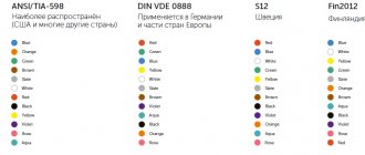
Don't forget about color codes, since mixed up colors often cause accidents. Sometimes, when opening a cabinet, you may not find any markings; in this case, you need to use probes to understand which wires serve which purposes.
A screwdriver with an indicator will help you determine the purpose of the wires, with which you can easily find zero and phase. During the verification process, it is necessary to leave markings so as not to confuse the assignments of the conductors in the future.
It happens that you have to install conductors with markings of the wrong color that is required. In this case, remember about other markings on the ends of cables and wires; they must always be correct.
Insulating tape can also help make markings, but it is better to use the materials we wrote about above.
Heat-shrinkable tubes, which can also be used for marking, look like this:
Marking must be carried out not only in the panels, but also in the automatic control panels. This is necessary to distinguish different conductors, for example, to immediately identify signal cables and other conductors.
This is the basic information you need to know when marking conductors. Do not ignore the markings and follow the rules that we described in the article!
Marking with color and other symbols will help not only simplify repair work and maintenance, but also save human life and health during electrical installation work. In addition, the marking process does not take much time.
Types of tags
The above labels may have different sizes. It depends on the amount of information required on its surface. To prevent mechanical damage to the conductors during the installation of the label, its material must be soft, it can be polystyrene.
If metal is used to make tags, the label should not contain sharp corners or jagged edges. They can cause damage to the sheath of the aluminum power wire.
What are cable tags made of?
A cable marking tag can have different sizes, which depends, among other things, on the amount of information placed on it. It can be made of various materials, but in any case, care must be taken to ensure that during installation the marking tag does not accidentally damage the wires.
You need to choose a soft material for making tags or make sure that hard marking labels (for example, metal) do not have sharp corners or jagged edges. This will help avoid damage to the insulating sheath of cables and wires.
Today, all marking tags available in the arsenal of electrical installation specialists are divided into three categories:
- classic cable with insert;
- solid plastic;
- made from PVC pipes.
Simple, time-tested and easy to use labels with insert. The necessary information is applied to the thick paper insert, after which it is simply inserted into the grooves on the tag.
The PUE is required to designate each electrical line in accordance with the regulations, regardless of where and in what way it is laid. If the power transmission route has several cable strands, then each of them is marked, indicating the main parameters and direction on the labels.
A tag is attached in front of each circuit breaker containing characteristics such as cable voltage and cross-section. The marking is applied to the labels with a marker that is resistant to external influences, including high temperatures. High-quality labels are not afraid of either corrosion or negative natural factors. They can be used both indoors and for outdoor electrical installations.
When laying the wire in a closed way, in a corrugated sleeve, the step for marking the wires should not exceed 50 meters. The labels are attached using plastic clamps or wire, firmly fixing them in the place selected in accordance with the PUE.
Types of tags
Branding of wires is carried out using factory-made or self-made tags. But their form must strictly comply within certain standards. These standards determine the types of labels used to mark cable lines. The following forms of these products exist:
Square. They designate power lines up to 1000 V. As a rule, these are lines for household use.
Round. They are used to show wires through which voltages exceeding 1000 V are supplied. Such lines are classified as industrial, which require a high degree of safety during installation and use.
Cable lines - marking requirements
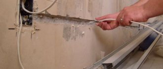
Cable lines are an integral part of electrical and communication networks. When laying any open cables, including power cables in cable structures (cable tunnels, floors, overpasses, etc.), markings are required on the cable sheath. Power routes are often bundles of cables laid in parallel, the main purpose of marking which is ease of operation and repair of cable lines.
Unlike the factory marking of cable products, which is applied to the outer sheath and carries information about the features of the product, the marking of electrical installation cables is applied to explain the purpose of the cable. It must correspond to the information reflected in the cable log compiled when laying electrical cables. Labeling rules and the basic requirements for it are reflected in the following regulatory documents:
- current edition of the rules for electrical installations – clause 2.3.23;
- rules for technical operation of consumer electrical installations – clause 2.4.5;
- SNiP 3.05.06-85 – pp. 3.103 – 3.106.
According to the requirements of all three documents, marking is carried out by installing tags on laid cables and cable joints.
Features of cable line marking
Taking into account the above-mentioned tag rules, the following are established:
- at the beginning and end of the cable line;
- in places where couplings are installed;
- at points of change in cable direction;
- along the entire length of the line at a distance of no more than 50 m;
- on both sides where obstacles pass (walls, ceilings, etc.).
When laying cables in trenches, tags are installed next to the end couplings; in addition, they must be placed on the connecting couplings.
Tag markers installed along the entire cable line must contain the following information:
- cable number according to technical documentation;
- type of cable products used;
- the number of current-carrying conductors and their cross-section;
- numbers of cabinets between which the cable is connected, indicating the source and consumer;
- the length of the cable.
For connecting couplings, the marker indicates the number of the connection itself and the date when it was installed.
Tag markers differ in their geometry and material of manufacture. Due to their purpose, they come in square, round and triangular shapes:
- square mark the power cables of networks less than 1000 volts;
- round tags are used for marking high-voltage lines (from 1 kV and above);
- Triangles mark current-carrying lines of control cables.
Often, a bundle contains several dozen conductive lines; markers of this size get tangled, interfere with each other, and even get destroyed. In such situations, you can use smaller tags with a special fastening, which indicate only the cable number.
Tags are made from various materials: steel, aluminum or plastic. For rooms with high humidity or aggressive environments, only plastic tags are allowed. Today, a large number of building materials are produced, including those for electrical installations, so tags of any shape made of wear-resistant plastics or PVC are easier to buy.
Designations may be applied in any way that prevents abrasion or accidental damage to the inscriptions. This can be engraving on metal surfaces or burning with subsequent filling with dyes on plastic; for rooms with normal conditions, symbols are often applied with indelible paints. The simplest, cheapest and fastest way to apply information to tags today is considered to be the use of special printers.
The need for crimping flexible wires
If you install stranded wires, the core of which can contain from several to several dozen thin wires, under a screw or other fastening, only by removing the insulation, it will not be possible to achieve high-quality contact.
Read more…
Why loop grounding is prohibited
The resolution of the dispute is suggested by the rules for the installation of electrical equipment (PUE) clause 1.7.144, which prohibits the connection of protective conductors with a loop; however, the desire to save on expensive cables and installation work pushes many electricians to violate them. So what is the danger? Why are PUEs so uncompromising regarding daisy chain connections? Read more…
Alphanumeric designations
GOST specifies regulations for marking the external insulation of cable lines, thanks to which cords, cables and wires can be distinguished from each other. If there are no markings on the braid or they are not sufficient for maintenance and safety, then special tags with additional data are attached to the route.
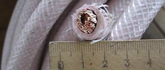
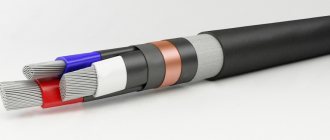
According to the rules and recommendations prescribed in GOST, a wire is a product consisting of one or more cores, which are protected with insulation along their entire length. The cores can be produced without insulation. A cable is defined as several conductors insulated separately from each other, placed under a single sealed sheath made of metal or polymer materials. A cord consists of two or more flexible conductors that are connected together by twisting or braiding. The cores are fixed along their entire length, and the braid is made from non-metallic materials.
All cables are divided into several groups:
- power;
- signaling and control;
- installation;
- radio frequency;
- connected.
You can decipher the alphanumeric symbols on the insulation yourself.
The first letter in the abbreviation indicates the material the core is made of. The letter “A” at the beginning indicates that the current-carrying conductor is made of aluminum. The absence of such a letter means that it is made of copper.
The second letter indicates the scope of application of the product. If the second letter in the abbreviation is missing, then such a cable is considered to be power.
The third letter is used to indicate the degree of flexibility of the product. Its absence indicates a single-core wire, the presence of the letter “G” indicates a flexible multi-core wire.
The fourth letter allows you to designate the material used to make the insulation. Windings are made from different materials, so more specific designations are used for it.
The fifth letter indicates the material used to make the outer shell and the presence or absence of an armored hull.
The sixth letter can be used to indicate the protective cover, the purpose of the layer and the structure as a whole.
Thanks to capital letters, you can indicate certain features of the cable line, the presence of certain properties. After the letter designations there are numbers. The first number indicates the operating voltage (“1” – 1 kV, without a number – 600 V), the second – the number of cores (1-37), the third – cross-sectional area.
Requirements for inscriptions on tags
Tags on the cable, secured with clamps or threaded through the wire, must be signed in a certain way; this rule is regulated by the rules of the PUE. In accordance with this document, the following data is applied to the label:
- Cable or line number. This is information that contains data about the direction of the highway, what it feeds, and what level of protection is required. During the wiring installation process, an object passport is drawn up, which indicates the buildings or premises powered by this line. They are assigned numbers, which will subsequently be written on the tag itself; during the service process, the technician will be able to look at the markings of the cables and, by comparing them with the object’s passport, understand where this or that line leads;
- Brand and cross-section of wire. Since space on the tag is limited, the designation is written abbreviated, with a minimum number of characters. For example, a vinyl-coated cable with a cross-section of 3*2.5 is briefly designated VVG-3/2.5;
- Line voltage. This is a mandatory parameter, since it is not clear from the outer sheath of the cables what voltage the current flows through it, respectively, and what level of protection is required during repair work;
- The beginning and end of cable lines. For more accurate information about possible losses on the main line after its installation, a designation of the total length is applied. After reading the data, the technician servicing the wire line will be able to accurately calculate the resistance and level of voltage loss in the network.
Labels on tags
All of the information listed is basic and mandatory. It is not prohibited to place additional information on the tag that characterizes the electrical main, for example, the date of laying. In addition, when placing a tag on the coupling, it is necessary to place the date of installation of the wire, since the coupling has its own resource, which will be calculated based on this indicator.
Inscriptions on metal tags are most often made by engraving with a special pencil or indelible paint. Plastic products are signed with a permanent marker or indelible paint. Also, when placing a tag using wire on a highway, it is necessary to additionally protect metal objects with bituminous composition or any other paint, otherwise the wire will rust and collapse, and the tag will be lost. Nylon thread is best suited for fastening; it is not afraid of temperature changes and high humidity.
Tag for threading onto wire
Recently, to indicate the cable on the line, many electricians began to use stickers that already have inscriptions informing about the voltage, as well as empty spaces in which additional data is written. Such stickers are very convenient, since the master does not waste time making markings, but simply glues the element onto the finished tag and continues installation.
Common labeling mistakes
Let's list three main mistakes:
- The most common one is caused by novice electricians or experienced specialists due to inattention. In the process of screwing the wire to the shield and terminals, the craftsmen simply forget to put a heat-shrinkable tube with markings (tube) on the wires. Because of this, you have to unscrew the attached wiring and put the products on again.
- Often craftsmen confuse the PEN conductor with a grounding cable. The fact is that both elements have identical color markings, so you need to inspect them more carefully.
- If the panel is located outside the site, then it is necessary to conclude an agreement with the electrical energy supplier. You must have on hand technical documentation with a diagram and confirmation of compliance with the requirements of the PUE, PTEEP and other regulatory acts. Otherwise, you may face claims from Rostekhnadzor.
Let's summarize: in accordance with the requirements and regulations prescribed in international and domestic standards, all power installations and cable lines without exception must be marked. The need for marking is not affected by either the voltage values or the location of installation (laying) of the circuit.
Qualified specialists will agree to carry out repair work and engage in maintenance of emergency areas only if sufficient information about the parameters of the line is provided. This is exactly what is contained on the cable tags.
Basic requirements for marking wires in switchgears (switchgears) and switchboards
Clause 1.1.30 of the PUE states that all wires in the control panel must correspond to the alphabetic, digital and color designations. The presence of a color designation does not exclude the installation of numbers and letters. It is allowed to apply markings not along the entire length of the line, but only at the connection points.
Marking begins with compliance with the rules during the installation process, when connecting wires according to the color of the insulation. This is the most clear example, which allows operating personnel to quickly navigate the purpose of each individual wire in the circuit. Sometimes cables with wires of the same color are used; in these cases, it is possible to paint the ends of the wires, put on cambrics of the corresponding color, or it is more practical to install a heat-shrinkable tube with alphabetic and digital values already applied. The length of the marker tube must be at least 2.5 cm.
Wire marking by color
In three-phase networks, each phase is designated by the letters A, B, C, but in apartments and private houses single-phase power supply circuits are used, so there is no point in specifying which phase of the substation your panel is connected to.
Letter designations:
- The phase wire is marked with the letter “L”;
- The neutral wire is designated by the letter “N”;
- Grounding wires are marked with a symbol
- In circuits according to TN-CS system standards, it is allowed to connect the grounding conductor to the neutral wire. In such cases, “PEN” is written on the label.
- In DC power supply circuits, for individual consumer devices the polarities “+”, “-” and the voltage in volts “12V or 24V...” are indicated.
Marking DC circuits
What do the tags tell you?
The PUE determines not only what tags should be on the cables, but also the mandatory information that they must contain, namely:
- power line number - allows you to find out its direction, identify the object powered by it, and determine mandatory safety measures. The installation of electrical wiring is accompanied by the creation of a passport for the building being serviced, a house in which all the premises supplied with electricity from this line are indicated. They receive numbers, they are applied along with other marking information. The presence of marking labels makes it much easier for specialists to maintain lines;
- wire brand and cross-section - space on the tag is limited, so the designation is carried out with a minimum number of characters. The cable brand is indicated by a generally accepted abbreviation;
- voltage level is an important mandatory characteristic, since it is difficult to understand just from the outside of the cable what current it carries;
- the location of the beginning and end of the line - data on the total length of the electric main, with which an electrician can easily determine the resistance of the wiring and the level of voltage loss in it.
The above characteristics and parameters must be applied to the tags without fail. If there is free space on the labels, you can place there any additional parameters characterizing the cable, for example, the time of its installation.
Tags installed on couplings connecting cables must contain information about the date of installation.
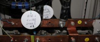
What else is important to know
The photo below shows the board in which the wires were marked during installation:
When assembling an electrical panel, electrical wiring groups should be marked as follows: the input wire is marked as L, and the output wire is marked Gr (indicates that these are groups). After the letter the group number and line number are indicated.
Also, during marking, it is important to take into account all color differences so that an emergency situation does not arise. If, after opening the cabinet, no markings were found, then you need to use a probe to determine where each wire is located.
We talked about how to use an indicator screwdriver to determine phase and zero in the corresponding article. Since this will take a lot of time, it is better to leave marks when checking so that another electrician who will carry out repairs or maintenance can understand where which wire is.
If there are no conductors of the required color, then you can use any color, as long as the ends of the cores are correctly marked during installation. This can be done using colored electrical tape or special heat-shrinkable tubes.
Heat shrink markings look like this:
This is the technology used to mark wires and cables when installing an electrical panel
As you can see, marking the lines is very important, and the process itself does not take much time
Please note that with the help of these instructions you can mark conductors not only in power electrical panels, but also in automation panels (for example, to mark signal cables and control)
It will be useful to read:
Wire tags printed on a cable printer
We have such a cabinet to control the pumping station:
Control cabinet - wires are not labeled, tags are needed!
Scheme:
Diagram of installation of water supply to the workshop
The circuit is simple, however, if you approach it for the first time, it will take time to figure out which wire is which. Therefore, wire tags are vital!
As a result, wires with stickers (tags) look much clearer:
Wires with tags printed on a BROTHER P-Touch printer
Labels on the control panel wires - it makes everything much easier!
I printed a test label on the pipe in a small font size on 9mm tape. It would be necessary to reprint it larger.
Sticker on water supply pipe, printed on BROTHER P-Touch
What else is important to know
The photo below shows the board in which the wires were marked during installation:
When assembling an electrical panel, electrical wiring groups should be marked as follows: the input wire is marked as L, and the output wire is marked Gr (indicates that these are groups). After the letter the group number and line number are indicated.
Also, during marking, it is important to take into account all color differences so that an emergency situation does not arise. If, after opening the cabinet, no markings were found, then you need to use a probe to determine where each wire is located.
We talked about how to use an indicator screwdriver to determine phase and zero in the corresponding article. Since this will take a lot of time, it is better to leave marks when checking so that another electrician who will carry out repairs or maintenance can understand where which wire is.
If there are no conductors of the required color, then you can use any color, as long as the ends of the cores are correctly marked during installation. This can be done using colored electrical tape or special heat-shrinkable tubes.
Heat shrink markings look like this:
This is the technology used to mark wires and cables when installing an electrical panel
As you can see, marking the lines is very important, and the process itself does not take much time
Please note that with the help of these instructions you can mark conductors not only in power electrical panels, but also in automation panels (for example, to mark signal cables and control)
It will be useful to read: