It's all about tension
Voltage is the potential difference between two points in space. Measured in volts. So the voltage between the positive and negative contacts of the battery is 1.5 volts, and between the surface of the earth and the thundercloud - millions of volts!
Effective value and amplitude value of voltage
When we say 220 or 380 volts, we mean effective voltage values, in other words, rms voltage values. In fact, the amplitude value of the alternating voltage is always higher than the phase Umph or linear Uml. For a sinusoidal voltage, its amplitude is greater than the effective value by the square root of 2 times (1.414 times).
It follows that a phase voltage of 220 corresponds to an amplitude voltage of 310 volts, and for a linear voltage of 380 volts the amplitude will be equal to 537 volts. Of course, in practice, the voltage in the outlet often does not correspond exactly to 220 volts; it may be more or less than this value, but it must be within acceptable parameters.
What is phase voltage in an AC network?
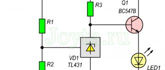
In a power plant, the generator windings are connected in a star configuration, that is, they are connected by the ends X, Y and Z at one point, which is called the neutral or zero point of the generator. This circuit is called a four-wire three-phase circuit. Linear wires are connected to the terminals of windings A, B and C, and a neutral or neutral wire is connected to the zero point.
The voltages between terminal A and the zero point, B and the zero point, C and the zero point are called phase voltages, they are designated Ua, Ub and Uc, but since the network is symmetrical, you can simply write Uph - phase voltage.
Three-phase line voltage
The effective voltage between terminal A and B, between terminal B and C, between terminal C and A is called linear voltage, that is, it is the voltage between the linear wires of a three-phase network. They are designated Uab, Ubc, Uca, or you can simply write Ul.
Source
How to calculate three-phase voltage
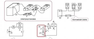
Industrial power transmission uses three symmetrically spaced voltage sinusoids, which are produced by generators.
The three windings of their rotor are spaced 120 degrees apart and rotate in the magnetic field of the stator, alternately crossing its lines of force. Therefore, a displaced electromotive force is induced in them in the same way.
The sinusoids are shifted among themselves by the same angle as shown to the right. Their vector expression on the complex plane is also displayed with an angle of 120°.
In this case, a system of linear and phase voltages is formed, shown in the picture.
A potential difference of 380 volts is formed between all linear wires. At the same time, relative to each of these conductors and zeros, the familiar 220 is present.
Such a system constantly operates in a balanced mode: the currents of single-phase consumers circulate through their closed circuits, constantly adding up in the neutral conductor. The addition is not purely arithmetic, but vector, taking into account the direction of energy flow.
Therefore, when geometrically adding vectors, the current in the zero wire decreases and, as a rule, it is made thinner than the other wires.
Formulas for electric voltage for linear and phase quantities, as well as currents, can be found directly in the picture.
Sinusoid of effective and amplitude voltage
It is clear that this material is more aimed at a simple audience, who not only do not have an oscilloscope, but probably not everyone even has a multimeter. Therefore, all examples will be taken from the Electronics Workbench environment, which is accessible to everyone.
And the first thing we need to look at is the phase voltage sine wave from the outlet. To do this, we will draw a three-phase network in the program and connect the oscilloscope to one of the phases:
As can be seen with a voltmeter reading of 219.4 Volts between one of the phases and the PEN conductor, the oscilloscope showed a sine wave with an amplitude of 309.1 Volts. This voltage value is called maximum (amplitude). And 219.4 Volts, which the voltmeter shows, is the effective voltage. It is also called root mean square or effective. And before we move on to consider this feature, let’s briefly, in simple words, go through the drawn diagram of a three-phase network and understand the nature of the sinusoid.
Let's start with the diagram:
Now let's look at a sinusoid. Alternating voltage, in contrast to constant voltage, the graph of which is straight on an oscilloscope, continuously changes both in magnitude and direction. Moreover, these changes occur periodically, that is, they are exactly repeated at regular intervals.
Alternating voltage is generated at power plants and reaches the end consumer through step-up and step-down distribution transformers. In this case, the transformation along the path does not affect the voltage sinusoid in any way.
Zero break: how it occurs and why it is dangerous
Normal operation of electrical equipment occurs in a balanced mode when voltage is normally applied to it. If zero disappears, then household appliances stop working.
There are important differences here when operating wiring assembled according to a single-phase or three-phase power supply circuit.
Zero break in a single-phase network: danger of occurrence
Apartment wiring is connected to supply voltage through two wires with phase and zero (ground loop) potentials. The electric load current that performs useful work can only flow through a closed circuit.
This means that if one potential from the winding of the transformer substation is not connected to a socket or light bulb in the apartment, then there will be no voltage on them, and, consequently, there will be no work.
However, there is a feature related to the safety of residents.
Typically, socket groups are assembled in a loop and connected in parallel to each other. The power cord plug of some appliance can be inserted into one of them: a refrigerator, washing machine, microwave oven, etc.
In such a situation, through the internal circuit of this device, the phase potential will pass to the zero contact of the socket and then to the end of the connected but broken wire.
Electricians say about this: two phases in the outlet! They are easy to notice with a single-phase voltage indicator. Its indicator light will light up in both contact sockets.
This mode is dangerous because the severed end is not insulated. A person may fall under the influence of the newly formed potential and receive electrical injury.
Three-phase alternator operation
Let's take a simplified look at the operation of a three-phase alternating current generator. The stator windings (phases A, B and C) of the generator are located at an angle of 120 degrees relative to each other. A rotating rotor with a magnet induces periodically changing EMF in the stator windings. It looks like this:
This rotation occurs at a frequency of 50 revolutions per second, that is, at a frequency of 50 Hertz. This means that electrons move within 1 second 50 times in one direction (positive half-cycle of a sine wave), and 50 times in the opposite direction (negative half-cycle), passing through zero value 100 times. It turns out that, for example, an ordinary incandescent lamp, connected to the network with such a frequency, will fade and flash approximately 100 times per second, but we do not notice this due to the peculiarities of our vision.
Determination of effective voltage
Now directly about why there was a transition from the maximum, amplitude voltage value of 310 Volts to the current 220 Volts. The answer can be found in the definition itself.
The effective (effective or root mean square) voltage value is the direct current voltage that, on the same resistive load, will produce the same power as the measured alternating voltage . Accordingly, the effective value of current is the value of direct current that, when passing through a resistive load, will release the same power as when passing the measured current.
It can be formulated a little differently. The effective value of an alternating current is equal to the value of a direct current that, in a time equal to one period of the alternating current, will produce the same work (thermal or electrodynamic effect) as the alternating current in question.
The general formula for calculating the effective voltage of an arbitrary shape is as follows:
Explanation of effective voltage
Definition and formula are good. But it’s better to understand everything with a clear example. Everything can be explained through power. Moreover, there is a difficult-to-understand method and a simpler one, which we will consider further.
We need to take one period of an alternating voltage sinusoid, construct an alternating current sinusoid on this interval and analyze the power. Let's start with the period of an alternating voltage sinusoid. Here we will construct an alternating current sinusoid taking into account a conditional resistive load (for example, a light bulb). According to Ohm's law, current is equal to voltage divided by resistance.
The exact values at a particular moment are not important in this explanation, therefore all constructions are approximate. Naturally, you need to understand that dividing the voltage by the resistance, we get an alternating current sinusoid with an amplitude R times less than that of the voltage. R is the resistance value.
Now, using two sinusoids, we build a power graph using the formula power equals current multiplied by voltage ( P = I × U ). Since voltage and current have common zero points, the power graph will not go into the negative region. That is, current with a “+” sign and voltage with a “+” sign will give power with a “+” sign, just as current with a “-” sign and voltage with a “-” sign will give power with a “+” sign.
Analyzing the resulting graph, it can be noted that the power is pulsating. It rises to a maximum value and falls to zero, then rises again and falls again. How do electrical appliances react to these power fluctuations? No way. Since the frequency of alternating current is 50 Hertz, these oscillations occur very quickly. Electrical appliances respond not to maximum and minimum power values, but to average ones. That is, the maximum power value is taken and divided by two. This value is called effective and is found using the following formula:
Pd = (Imax × Umax) / 2 , where Pd is the effective power, Imax is the maximum current, Umax is the maximum voltage.
Two can be represented as root of two times root of two. We get the effective value of power = maximum current divided by the root of two multiplied by the maximum voltage divided by the root of two ( Pd = (Imax/√2) × (Umax/√2) ).
Accordingly, the maximum current divided by the root of two is the effective value of the alternating current , and the maximum voltage divided by the root of two is the effective value of the alternating voltage .
Indeed, if we take the maximum voltage from the previous example, 309.1 Volts, and divide by the root of two, we get an effective voltage (the one shown by the voltmeter) of 219.4 Volts.
Source
What does a voltmeter show, or socket mathematics?
What is this article about?
Today I'll take a brief detour from my usual topic of visual programming of controllers and address the topic of measuring voltage right there, in the socket!
This article was born from discussions over tea, when a dispute broke out among “omniscient and omniscient” programmers about what many of them do not understand, namely: how the voltage in an outlet is measured, what an AC voltmeter shows, what is the difference between peak and effective voltage values .
Most likely, this article will be of interest to those who are starting to create their own devices. But perhaps it will help someone more experienced to refresh their memory.
The article talks about what voltages exist in the AC network, how they are measured, and what to remember when designing electronic circuits. Everything is given a brief and simplified mathematical justification so that it is clear not only “how”, but also “why”.
Those who are not interested in reading about integrals, GOST standards and phases can immediately move on to the conclusion.
Introduction
When people start talking about the voltage in an outlet, very often the stereotype “220V in an outlet” hides the real state of affairs from their view.
Let's start with the fact that according to GOST 29322-2014
, the mains voltage should be
230V±10%
at a frequency of
50±0.2Hz
(phase-to-phase voltage
400V
, phase-neutral voltage
230V
).
But in the same GOST
there is a note: “
However, 220/380 V and 240/415 V systems still continue to be used
.”
Agree that this is not at all the same as in a 220V outlet
", to which we are accustomed.
And when we start talking about “ phase
”, “
linear
”, “
effective
” and “
peak
” voltages, it’s a big mess. So how many volts are there in an outlet?
To answer this question, let's start with how voltage is measured in an AC network.
How to measure AC voltage?
Before delving into the jungle of AC and voltage circuits, let’s remember the school physics of DC circuits.
DC circuits are a simple thing. If we take some active load (let it be an ordinary incandescent lamp, as in the figure) and plug it into a DC circuit, then everything that happens in our circuit will be characterized by only two quantities: the voltage across the load U
and the current flowing through the
load
I. The power consumed by the load is uniquely calculated using the formula known from school: .
Or, if we consider that according to Ohm's law
, then the power
P
consumed by the light bulb load can be calculated using the formula.
With variable voltage, everything is much more complicated: at each moment of time, it can have a different instantaneous value. Consequently, at different points in time, different power will be released at a load connected to an alternating voltage source (for example, an incandescent lamp plugged into an outlet). This is very inconvenient from the point of view of describing the electrical circuit.
But we were lucky: the voltage in the outlet is sinusoidal. And a sinusoid, as you know, is completely described by three parameters: amplitude, period and phase. In single-phase networks (and a regular socket with two holes is precisely a single-phase network), you can forget about the phase. The figure shows in detail two periods of single-phase mains voltage. The same one that is in the outlet.
Let's look at what all these letters in the picture mean.
Period T
is the time between two adjacent minimums or adjacent maximums of a sinusoid.
For the RF lighting network, this period is 20 milliseconds
, which corresponds to a frequency of
50Hz
. The frequency of voltage fluctuations in the electrical network is maintained very accurately, down to a fraction of a percent.
It is obvious that at any two points of the sinusoid, separated from each other by an integer number of periods, the voltages are always equal to each other.
Amplitude Um
- this is the maximum voltage, the peak of the sinusoid.
about the effective voltage Ud
a little lower.
The voltage in a socket (or single-phase network) is described by the formula
where t
is the current moment in time,
Um
is the amplitude (or peak value) of the voltage,
T
is the period of the mains voltage.
If everything is more or less clear with single-phase alternating voltage, then let’s try to calculate the power that is released by our favorite incandescent lamp when it is plugged directly into the socket.
Since an incandescent lamp is an active load (which means that its resistance does not depend on the frequency of voltage and current), the instantaneous power released by an incandescent lamp plugged into a socket will be calculated by the formula
where t
is the current moment in time, and
R
is the resistance of the incandescent lamp with a heated coil.
Knowing the amplitude of the alternating voltage Um
, we can write:
It is clear that instantaneous power is an inconvenient parameter, and in practice it is not particularly necessary. Therefore, in practice, power averaged over a period is usually used. It is the average power that is indicated on light bulbs, heaters and other household irons.
The average power is calculated in the general case using the formula:
And for our sinusoid - according to a much simpler formula:
You can substitute it yourself
function and take the integral if you don’t believe me.
Don’t think that I just remembered about power out of spite. Now you will understand why we needed it. Let's move on to the next question.
What does the voltmeter show?
For DC circuits, everything is clear here - the voltmeter shows the only voltage between two contacts.
With AC circuits everything is again more complicated. Some (and these are not so few, as I was convinced) believe that the voltmeter shows the peak voltage value Um
,
but that's not true
!
In fact, voltmeters are usually
show
the current
or
effective
, also known as
root-mean-square
, voltage in the network
Ud
.
Of course, we are talking about AC
!
Therefore, if you measure the network voltage with a voltmeter, be sure to make sure that it is in AC voltage measurement mode
.
I’ll make a reservation that “peak voltmeters” that show amplitude voltage values also exist, but in practice, when measuring the voltage of the supply network in everyday life, they are usually not used.
Let's figure out why there are such difficulties. Why not just measure amplitude? Why did they come up with some kind of “effective value” of voltage?
It's all about power consumption. I didn’t just write about her. The fact is that the effective (effective) value of an alternating voltage is equal to the value of such a direct voltage, which, in a time equal to one period of this alternating voltage, will produce the same work as the alternating voltage in question
.
Or, simply put, an incandescent light bulb will shine equally brightly whether we plug it into a 220V
or into an alternating current circuit with an effective voltage value of
220V
.
For those who are already familiar with integrals or have not yet forgotten mathematics, I will give a general formula for calculating the effective voltage of an arbitrary shape:
From this formula it also becomes clear why the effective (effective) value of the alternating voltage is also called “rms”.
Note that the radical expression is the same “power averaged over the period”; you just need to divide this expression by the load resistance R
.
In relation to the sinusoidal voltage form, the terrible integral after simple transformations will turn into a simple formula:
where Ud
is the effective or rms value of the voltage (the same one that is usually shown by a voltmeter), and
Um
is the amplitude value.
The good thing about the effective voltage is that for an active load, the calculation of the average power completely coincides with the calculation of the DC power:
This is not surprising if we recall the definition of the effective voltage value, which was given just above.
And finally, let’s calculate what the voltage amplitude in a 220V
«:
In the worst case, if you have a 240V network, and even with a tolerance of +10%, the amplitude will be as much
!
Therefore, if you want your mains-powered devices to operate stably and not burn out, choose elements that can withstand peak voltages of at least 400V
. Of course, we are talking about elements that are directly supplied with mains voltage.
I note that for a non-sinusoidal waveform, the effective voltage value is calculated using different formulas. Those who are interested can take the integrals themselves or refer to reference books. We are interested in the supply network, and there should always be a sinusoid there.
Phases, phases, phases...
In addition to the usual single-phase lighting network
Everyone has heard of 220V and three-phase network
380V. What is 380V
?
And this is the interfacial effective voltage
.
Remember when I said that in a single-phase network you can forget about the phase of the sinusoid? So, this cannot be done in a three-phase network!
To put it simply, phase is the time shift of one sinusoid relative to another. In a single-phase network, we could always take any moment in time as the starting point - this did not affect the calculations. In a three-phase network, it is necessary to take into account how far one sinusoid is from the other. In three-phase AC networks, each phase is separated from the other by a third of a period or by 120
degrees.
Let me remind you that the period is also measured in degrees and the full period is 360
degrees.
If we take an oscilloscope with three beams and focus on three phases and one zero, we will see the following picture.
«Blue
» phase - starts from zero reference.
“ red
” phase is a third of the period (
120
degrees) later.
And finally, the “ green
” phase begins two-thirds of the period (
240
degrees) later than the “
blue
” phase. All phases are absolutely symmetrical relative to each other.
It doesn’t matter which phase to take as the starting point. The picture will be the same.
Mathematically, we can write down the equations for all three phases:
«Blue
» phase:
«Red
» phase:
«Green
» phase:
If you measure the voltage between any of the phases and zero in a three-phase network, you will get the usual 220V
(or
230V
or
240V
- depending on your luck, see
GOST
).
And if you measure the voltage between two phases, we get 380V
(or
400V
or
415V
- don’t forget about it).
That is, a three-phase network has many faces. It can be used as three single-phase networks with a voltage of 220V
or as one three-phase network with a voltage of
380V
.
Where did 380V
? And here's where it comes from.
If we substitute our data on any two phases into the formula for calculating the effective voltage, we get:
Udf
- effective
phase-to-phase voltage
, also known as
linear
voltage.
Considering that the amplitude of each phase
we obtain that for the interphase voltage.
The figure clearly shows how the interphase voltage is formed, which is designated F1-F2
from two phase voltages phases
F1
and
F2
.
The voltage of phases F1
and
F2
is measured relative to the neutral wire.
Line voltage F1-F2
is measured between two different phase wires.
As we see, the effective interphase voltage is greater than the amplitude of the sinusoidal voltage of one phase.
The amplitude of the interphase voltage is:
For the worst case ( 240V
and phase-to-phase voltage
415V
, plus
10%
on top) the amplitude of the phase-to-phase voltage will be:
Take this into account when working in three-phase networks and choose elements rated at least 650V
, if they have to work between two phases!
I hope it is now clear what the AC voltmeter shows?
What is tension and how to easily represent it
I like the comparison of electrical processes with more understandable mechanical phenomena. That's why I show this picture.
We have some kind of hill with a height h relative to the initial level. At the top there is a load weighing R. It is not secured and can roll down under the influence of very little force, for example, a blow of wind.
But it is not there, and if it blows, the load will fall to a height of h2. In this case, they will perform work associated with moving a distance h1.
The same analogy, in my opinion, works in electrical engineering.
We consider two different potentials φ1 and φ2, which have accumulated different material bodies, for example, clouds during the movement of air masses with opposite signs of charges q.
They are separated by a layer of air atmosphere with resistance R, which prevents the movement of charge q.
In the same way, sparrows sit on an overhead wire and even a stork has woven its nest on an overhead line pole, as shown in the top picture. But nothing happens to them yet: they are separated from the second potential by a large resistance.
However, under the influence of wind, the load P can roll down, and the clouds move relative to the ground and each other: the air gap between them changes.
At some point in time, the potential difference φ1-φ2 between the charged bodies will break through the resistance R and work will be done to move the charge q.
So we get the definition of the formulation of voltage U, as the difference in potentials φ1 and φ2 or the work A performed when transferring charge q.
Voltage is measured in volts using special devices called voltmeters. It appears on all electrical circuits where different potentials are present:
- phase and neutral wires of home wiring when power is supplied from the transformer substation;
- tires of the entrance panel to the house or entrance;
- contact terminals of any charged battery or galvanic cell;
- output contacts of the switched on power supply, charger;
- many other places.
When the load P has already rolled down or the potentials φ1 and φ2 have discharged between each other, then the work of moving the charges cannot occur. In this case, if φ1-φ2=0, there is no voltage.
I admit that an experienced electrician will not be satisfied with this explanation of mine due to simplifications. Well: write in the comments. We will come to a common opinion. After all, I outlined the most basic knowledge for beginners.
Types of voltage in an apartment in simple words
But here we need to focus on how the potentials of electrical energy charges are formed.
How do DC power supplies work for household appliances?
At the output terminals of solar cell elements or galvanic cells, assemblies from them, potentials of charges of opposite polarity accumulate: positive and negative. They form constant voltage circuits.
On the time graph it is drawn with a horizontal line U, which does not change its value.
Although in principle this is quite conditional: as the discharge from the applied load occurs, the potential difference decreases (nothing is eternal in our lives) and the signal level still drops over time. But this quality is usually neglected in calculations.
How to determine voltage level
If we return to the definition of a term based on the potential difference or the work done to move charges, we will find ourselves in a dead end: it is impossible to evaluate them using simple methods.
In practical work with DC circuits, they use the measurement or calculation of electrical quantities based on the well-known Ohm's law for the circuit section U = i * R.
A simple online calculator designed for these purposes greatly facilitates such calculations. In addition, it is built on the use of one more function: the power consumption of the device included in the electrician’s cheat sheet.
You can use any of the above methods. Each electrical voltage formula given works correctly.
AC circuits in an apartment: where they come from and how they are formed
Electrical energy is supplied to houses and apartments from transformer substations of various voltages via 0.4 kilovolt (kV) power lines.
How does voltage appear in an outlet?
From the transformer substation, electricity is supplied to the apartment via:
- two-wire circuit - TN-C grounding system;
- or three-wire - TN-S or TN-CS grounding system.
They use different protection algorithms in emergency situations.
In the first case, less electrical safety is ensured. When a breakdown of the insulation of a household appliance occurs on the housing, a person who happens to be nearby receives an electrical injury: a dangerous potential passes through his body to the grounding circuit of the substation.
The three-wire wiring diagram immediately ensures the removal of dangerous potential through an additional circuit of the protective PE conductor.
This picture contains some simplifications, which I used so as not to complicate the understanding of the processes. They will be discussed in other articles.
If you disconnect the phase or zero potential from the socket, you will not be able to do the work: there will be no voltage in it - there is no potential difference.
The formulas for calculating voltage for alternating current given in the electrician's cheat sheet remain valid. But, in practice, it is necessary to take into account many nuances of the operation of electricity, equipment connection diagrams, and features of the passage of frequency signals.
Important characteristics of a sine wave for performing calculations
Electricity is produced by industrial generators that operate on the principle of rotating a rotor with turns of an insulated wire (frame) in the magnetic field of the stator.
A sinusoidal voltage of symmetrical alternating shape with harmonic oscillations is created at their terminals.
A sinusoid is characterized by the following parameters:
- amplitude;
- frequency or period of oscillation;
- phase.
In this case, phase is understood as the angle shift between signals of different sinusoids or relative to the origin of coordinates.
What is effective voltage
When measuring and calculating the parameters of a sinusoid, one should take into account the fact that its value constantly changes over time from zero to the maximum value and back.
To eliminate errors and carry out calculations correctly, the designation of effective voltage has been adopted.
Its value corresponds to the work that one harmonic half-wave can do. It is equated to the action of direct current for the same time T/2.
To do this, determine the area of half the harmonic using integral calculation for a half-cycle. Equate it to a rectangle with the same width.
Next, calculate the height by dividing the area by the width. The effective voltage value is obtained. It is √2 or 1.41 times less than the amplitude sinusoidal U max.
You can use another formula for calculating the effective voltage based on the amplitude: multiply it by 0.707.
All measuring instruments - voltmeters - work by determining the effective voltage value, and not the amplitude.
For comparison: the usual value of 220 volts is effective, and the amplitude is 310.
What is “impulse voltage”
In your practice, you need to be prepared for the fact that an overvoltage pulse from an emergency mode in the power supply system, for example, from a lightning strike into an overhead line, may penetrate into household wiring.
The overhead lines are equipped with special protection against such cases: arresters. They extinguish the resulting discharges, triggering in several stages.
But still, such an impulse, albeit of a reduced magnitude, penetrates through the wires into household appliances. It can damage their internal circuitry.
To protect against it, SPDs (surge protection devices) are used, which are calculated and selected for local conditions.