The advantage of the Splan design program, created by the developers of the German company Abacom, is its ultra-low amount of disk space. This program can be downloaded and carried on a flash drive; it does not require installation or any bells and whistles.
This is what the interface of the Splan program looks like
Also in the seventh version of the program, a compact viewer has appeared, which allows you not only to show the drawing to the client on his computer, but also to print it immediately.
General characteristics
The Splan design software has an intuitive interface. With a minimal set of tools, it allows you to create drawings of varying complexity. In addition to its own format, drawings can be exported to popular graphic formats BMP, GIF, JPG. That is, the finished drawing can be sent to the customer in the form of a drawing.
Designing in this program is a pleasure. Here you can find:
- ruler;
- grid with variable cell size;
- grouping of objects;
- automatic size setting;
- text;
- inserting pictures;
- coloring objects and lines;
- background, foreground;
- generating sheets into one file;
- element libraries;
- templates
The Splan program is indispensable when designing plans, sketches, structural diagrams, and albums of similar diagrams.
Creating a new library
If you click on the image of a book next to the list, a context menu will appear in which you will be asked to use a standard database or a custom one. Here you can either remove one of them or add a new one by following these steps:
- when selecting the “add” command, select the path along which the program will access the new database;
- You also need to enter the name of the new element database there;
- to use a previously created library, you need to create a folder and insert new data into it;
- Place the new folder in the directory according to the suggested path.
In the same way, it is permissible to transfer libraries from one PC to another computer.
Any user can download and install the graphic editor sPlan 7.0 rus. Compared to other similar programs, for example, Microsoft Visio (any version), Plan is much clearer and more convenient to work with. Its paid development will allow you to use all the added options.
sPlan.OPS
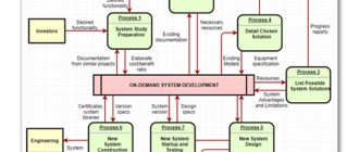
Based on the Plan program, a convenient and unique application has been created that can be used by both professional engineers and representatives of small and medium-sized businesses and individuals. Its main functionality is the design of fire and security alarms, video monitoring and surveillance systems.
The system is based on the sPlan platform version 7. In fact, all that remains of the well-known product is a convenient shell: the principle of constructing a diagram and drawing, a clear interface and portable principles of operation. The rest of the filling has been carefully reworked.
In particular, the databases have been completely updated and re-uploaded. The libraries correspond to the narrow specialization of the application and contain a complete set of tools that allows you to create a complete installation diagram for fire and security alarms, develop a detailed plan for installing and connecting CCTV cameras, both external and indoors.
The element databases are logically structured and have clear subheadings and sections. In order to find a specific element required for the diagram, just click on the desired section, and then, using the mouse, select the appropriate item from the list.
To Do Reminder
The program can be called both a task scheduler and a reminder manager. The user does not need authorization, although synchronization with other services requires an account. You will have to restore information manually from the memory card. The scheduler does not have Russian language support, but the interface is simple and does not require special knowledge of English.
To Do Reminder features include:
- adding and viewing new tasks;
- monitoring the history of assigned tasks;
- supplementing information with audio files and text comments;
- synchronization with other services - including Google Calendar and Facebook.
This is also a multi-platform application - there are versions on MacOS, Windows and Android
Quick search for a task by name and creation of tasks with audio notifications make the program very convenient for those who often forget to look at the to-do list and miss something important. However, the free To Do Reminder program does not support cloud storage and synchronization with other gadgets, so this planner is not suitable for every user
sPlan 7.0.Scheme
In addition to occupational safety engineers and individuals planning the safety of their own home or business, the Plan will be useful to those who are interested in electronics professionally or as a hobby.
Another useful application based on the version 7 platform is sPlan.Scheme. A simple and intuitive graphic editor allows you to develop and create detailed electrical circuits. Moreover, these can be either very simple amateur sketches or professional projects that take up several sheets.
The already familiar work area is equipped with the necessary tools. The work is facilitated by rich libraries containing the necessary elements-blanks. All work is done using the mouse; no special knowledge or skills are required.
The advantage of Plan over other similar products is again the richness and convenient structuring of libraries. In addition to the fact that each element can be found in its own section, its type and subtype can be selected, editing of any detail is also available. This is done in a separate pop-up window with settings.
Among the automatic functions that greatly simplify the designer’s life, the following points can be noted:
- automatic recognition of element pins and linking lines to them;
- automatic numbering of elements;
- snapping elements to the grid;
- grouping elements if necessary.
Radio amateur
The sPlan program is a simple and convenient tool for drawing electrical diagrams on a computer screen. The sPlan program has a Russified version and is deservedly popular among radio amateurs.
Good afternoon, dear radio amateurs! Welcome to the website “Amateur Radio”
There are many versions of the sPlan () program, but we will look at the operation of this program using the example of version sPlan 7.0 , which does not require installation on your computer, just download it, unzip it and you can immediately start working.
sPlan_7.0.0.9.rar (2.6 MiB, 21,505 hits)
After downloading and unzipping the program, double-click on the program launch icon and look at the screen.
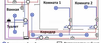
Below is a screenshot of the running program in the electrical circuit editing mode:
By the way, you can view any picture in enlarged form by clicking on it. This is what the running program window looks like. This window can be divided into several functional parts:
1st part: window for drawing electrical circuits:
This window is a field with a grid in the form of lines or dots, or without them at all, and two rulers - horizontal and vertical (in millimeters).
2nd part: window of the library of radioelements and related components:
Library selection. Here you can select the standard or your library of radio elements, or other libraries, also created by you or downloaded from the Internet.
Selecting a category of elements. Here you select the category of radio elements you need: transistors, diodes, coils, etc.
Selecting radioelements from a category. Here a specific radio element is selected (in this case, an npn or pnp transistor, etc.).
The number of columns when displaying elements is in this case 2 columns (no comment required).
Displaying descriptions of radio elements. When this option is enabled, a brief description of them (if any) will be displayed under the radio elements.
Moving to the next category is the same as selecting a category of radio elements.
3rd part: main menu:
♦ file: standard set of options: – create – open – save – template (selecting parameters of the sheet on which the diagram will be drawn) – upload an image (in BMP or JPEG format) – export – clipboard – print All options are standard for any program and special ones no comments required
♦ editing: – undo – repeat – cut – copy – paste – duplicate – repeat Also a completely standard set of options that does not require comments
- sheet: - properties
Here you select the sheet format, its name and an extended description.
– new sheet:
Here a new sheet is added and its place among all sheets in the project.
– duplicate:
Here an existing sheet is duplicated and its place among the other sheets is indicated.
– the remaining options do not require explanation.
— form: here you select or edit the form of the sheet on which the project will be developed; sample forms can be viewed by selecting the “open form” option. No special explanation required.
— service: also a fairly standard set of options that are very easy to understand.
— options: — basic parameters. Multi-page menu:
Main parameters. No special explanation required. But, of course, you can experiment in the future.
The following menu is directories:
Where drawings, forms will be saved and where graphics will be exported.
The next menu is libraries:
Here you can configure the following parameters: create a library, delete a library, give it a name, specify the storage location for the library.
The following menu fonts:
Here you can tell the program what font you will use by default.
Of the remaining options, let's consider two more - grid and scale:
Net. Here the default grid view is set on the diagram drawing field.
Scale. Default settings for the horizontal and vertical rulers of the diagram drawing field.
- default line styles:
Here you select the style of lines that connect components, and create new elements.
- default polygon styles:
Here you select the outline and fill styles of polygonal shapes.
♦ component: this section is the creation of a new radio element, we will look at it a little later.
Part 4: three panels for working with electrical circuits
♦ first panel (top):
♦ second panel (side):
♦ third panel (bottom):
Well, finally, we looked at what the program consists of and the purpose of its panels and buttons. Now let's move on to the practical part - drawing an electrical circuit.
We will take as a basis the circuit of a simple power supply:
To draw this circuit, we need: a transformer, a diode bridge (or 4 separate rectifier diodes), three electrolytic capacitors, one non-electrolytic capacitor, two 0.5 W resistances, one variable resistance, two separate diodes, a KREN type voltage stabilizer chip and an LED . Select all the necessary elements in the library window and place them in the diagram drawing window:
This is approximately how you should get the picture. You probably noticed that when you drag and drop elements, they are automatically numbered, which is, in principle, very convenient. When selecting elements in the library, we did not find two elements - a variable resistor and a KREN type microcircuit, so we will have to create them ourselves. First, let's create a variable resistor. To do this, use the “components” option in the main menu. By expanding the option we will see the following choice: create a component from the selected one, split the component, copy the component to the library and labels, that is, we do not have a choice to create a new component. A new component can be created using some other one as a basis. Let's select another constant resistor from the library without power marking. Double-click on the resistor and get to the element editing menu:
We fill in the corresponding sections of the menu: designation – leave it as R; nominal - set 5.1 K (as per the diagram); description – variable resistor. Next, click the “editor” button and go to the menu for editing the appearance of the element:
In the top menu, select the “grid” option and set the grid value to 1 mm (recommended). Next, in the left menu, select the “line” option and draw an arrow to the center of the resistor (drawing order: select the point where the line will begin, left-click, draw the line in the desired direction and the desired length, left-click, right-click):
A new component called a variable resistor is ready. Select the “component editor” menu and in it the “save and exit” option. At the same time, we will again return to the circuit drawing menu, where we will see the resistor we edited:
Now we need to save the created component in the library. In the library, select and open the resistors category, right-click on the variable resistor, a menu appears in which we select the very last line “copy components to the library. At the very end, our component should appear in the library:
By the way, if you enter the cursor into the library area and right-click, a menu will appear through which you can create an element from scratch. But it is more convenient to create a new one by editing an element.
A little about left clicks. One click – selecting an element, a second click – switching the element to rotation mode, two quick clicks – switching to editing mode.
Now let's create a microcircuit. Let's take the variable resistor we created as a basis. Select it with one click, then in the main menu select the “duplicate” option (the “x2″ icon), install the second variable resistor in an empty space and with two clicks on it we go into editing mode. Fill in the fields: designation - DA, in the nominal column - name of the microcircuit - KR142EN12, description - voltage stabilizer. And then by pressing the editor button we switch to element drawing mode. We remove the antennae from the arrow, stretch the body, select the entire element, rotate it 90 degrees, and move the “designation” and “denomination” to the place we need. Next to the legs of the resulting element we insert the inscriptions IN, OUT, GND (or numbers 2,8,17, indicating the pins of the microcircuit) and we get something like this:
Next, select the component editor, save and exit. We get a new element in the diagram drawing window:
Naturally, it may look different for you. Now let’s create a new category in the library for our microcircuit, for example – “microcircuit stabilizers”. To do this, enter the cursor into the library field and right-click. In the menu that appears, select the option “create a new library section”, a new section with a blank field will appear. Right-click on the newly created element and in the menu that appears, select the option “copy components to library”. And the first component will appear in our new section:
Now let's move on to the most important thing - drawing the diagram. To do this, first, we compose the future diagram by arranging the details on the drawing field. We get something like this:
The next step is to write down the values of the radio components (resistors, capacitors, diodes), and also expand the capacitor C3 - plus side up and expand the names of resistors R2 and R3 and diode D2. Let's consider the procedure for resistor R3. (At the same time, we’ll change the numbering order of the resistors). Two clicks on resistor R3 go to editing mode. In the designation we put R1, uncheck the auto-numbering box, set the denomination to 15K (as per the diagram), press the editor button and go to the element drawing mode.
Here we rotate the “designation” and “nominal” by 90 degrees and set it to the right of the resistor body (one click – selection, second click switches to the element rotation mode), and we get this view:
After that, click the “green checkmark” and return to the program. The resistor now looks like this on the diagram:
We do the same with the rest of the radio elements, and we get the following picture:
And finally, the last stage. In the left panel, select the “line” option and use it to draw lines, connecting radio components in accordance with the diagram. It is recommended to make the power lines first. After all the connections have been made, select the “node” option in the left panel and place points at the intersections of the lines where they should be connected according to the diagram. The output we get is something like this:
Next, using the options in the left panel, we apply the appropriate labels. Then save the created diagram to your folder. You can also bring your scheme to a more civilized look. To do this, select “form” in the main menu and in it the “open form” option. In the window that appears, select the form we need and get the following picture:
We fill out the fields in the lower right corner, print it out and present it to the experts.
This concludes the description of the program. If anyone has questions, or found errors, inaccuracies, or typos, please report them in the comments.
Text capabilities of Splan7
The plan can be used both for very specific purposes and for solving simpler, but no less popular problems. The program is equipped with good text and visual editors that allow you to create template printed products, as well as visual demonstration posters and presentations.
Using template solutions, you can create business cards, booklets and other products needed in business in sPlanе.
Integrated libraries of various profiles allow you to clearly demonstrate the work performed or present the capabilities of the designer.
Various fonts, multimedia support in electronic presentations and other text editor capabilities can become, if not the main functionality of the program, then a pleasant addition for designers talking about their developments.
Advantages and disadvantages
Like any other application running under Microsoft Windows, our program has a number of characteristic positive and negative features.
Advantages:
There are huge libraries of conductors, parts, connectors, etc., which fully comply with GOST standards. You can always choose the right part, the right denomination. To make this search more accurate, we recommend using a custom filter.
Flaws:
- This application is not easy for beginner electronics engineers to understand. To better understand the issue, they should watch one or more training courses and only then get started. If you have any questions during use, you can ask them in the comments to this article.
- Some very necessary electric motors are missing from the spare parts database. But in the next version this flaw will most likely be eliminated.
Next, let's look at a simple example of working with our application.
Program desktop
Electrical safety program: 2nd group
In addition to the white field, for constructing a drawing or diagram, the following layout is located on the program desktop:
- Main menu;
- control Panel;
- toolbar;
- library;
- properties control panel.
Working with files, editing a picture, changing the format, setting styles - all this is set using the main menu.
In the control panel they work with files: open, save, print, change the scale and set the grid. This is where the numbering of pages for ranking and the search for the necessary components take place. One of the options in this panel allows you to select a color for parent and child objects.
Using the toolbar, the user controls the tools for constructing diagrams. Inserting shapes and text blocks, drawing lines and polygons, measuring, adjusting scale - these are just some of the options in this panel.
The library has an extensive database of graphic symbols and images of radio and electrical subjects. You can store your own created templates and favorite graphics sets in it. To use the necessary objects, drag them onto the sheet with the mouse.
The control panel options in the program are set to default. If it is necessary to work in accordance with individual parameters, then they are changed separately using the appropriate desktop interface commands.
Description
This software is for lovers of electronics and radio, and is also recommended for use by students of specialized specialties for use in the educational process. Popular Russian versions – splan 7.0 rus, splan 8.0 rus.
Attention! Versions of the program are designed for different operating systems (OS), which you should pay attention to when downloading software for installation. Technical characteristics of the program splan 7.0.0.1 (7.0.0.4) Rus Edition:
Technical characteristics of the program splan 7.0.0.1 (7.0.0.4) Rus Edition:
- software developer – Abacom Electronics;
- installation platform – PC;
- OS requirements: Win 95.98,NT,2000,XP,Vista;
- the amount of space occupied on the hard drive is 6 MB;
- RAM – 256 MB;
- required video card – 32 MB;
- Russian language.
When installing and using the program, it does not require additional executable files (“cracked.exe”, “crack”, “keygen”, “trial reset”, etc.). The free version for electronic circuit designers allows you to display and display the finished drawing in convenient formats: BMP, JPG, GIF, EMF and SVG. Inserting custom files into an executable schema is one of the advantages of the software. The work is carried out using mouse manipulations. The library contains a detailed selection of elements arranged into groups.
Alternatives to Planoplan
| Program | Logo |
| Interior Design 3D is a program for Windows from a domestic developer. This is an excellent analogue of Planoplan. The main purpose is to design apartments and think through the interior, so here you can easily draw the necessary rooms, choose the finishing for them and arrange the furniture the way you want. And most importantly, it does not require an online connection to work. | |
| Sweet Home 3D is a multilingual editor for creating design projects. Suitable for working on Windows, Mac, Linux. Allows you to draw detailed floor plans: add rooms, select finishes and furniture. | |
| Planner 5D is software in Russian designed for creating layouts of houses and apartments. Supports iOS 5.0+, Windows, macOS. There is a version for iPad and Android. | |
| Floorplanner specializes in creating home floor plans. Works in English. The disadvantage of this program to replace Planoplan is that you cannot copy floors during operation: you will have to start from the beginning each time. | |
| Roomtodo is another online service that allows you to create rooms and view them as blueprints, in first person, or in 3D. | |
| Autodesk Homestyler is an English-language interior design software. Similarly, Planoplan works in a browser and requires authorization. | |
| Remplanner is a free online interior design software. The catalogs present many pieces of furniture and finishing options. However, a significant disadvantage is the lack of a ruler, so it is difficult for users to understand how much free space remains in the room. | |
| ArchiCAD is a professional modeling program. The software is paid and is most suitable for experienced users. | |
| 3dsMax is one of the most popular programs and a good alternative to Planoplan. The software has a large number of tools. However, not every user will be able to understand all the nuances. | |
| SketchUp is a free 3D drawing program for non-commercial use. There is also a paid version with wider functionality - SketchUp Pro. A Google account is required to operate. | |
| VisiCon is a shareware program for apartment planning. With its help, you can create rooms of different sizes and arrange them in the desired way. Works great with Windows. | |
| Aston design - free software for creating 3D plans. After completing the development of the plan, you can send the result to the manufacturer to calculate the cost of the selected furniture. | |
| PRO100 allows you to create an exact copy of real rooms and select furniture for them. The software is designed for advanced users and runs on Windows OS. | |
| IKEA Home Planner is a program from IKEA that allows you to quickly think through the furnishings of your apartment. The furniture catalog presents items exclusively from this manufacturer. | |
| Home Plan Pro is an English-language program for thinking through the layout. The result can be saved as a PDF or as a JPG, GIF or BMP image. |
Remember the Milk
A program that provides effective planning with information storage in the cloud. The planner also has support for custom lists and tags, syncing, and easy touch input.
Other noteworthy features include:
- control workflows using sorting and multi-user interaction;
- moving all tasks to the inbox by default;
- connection of tasks with geolocations and contacts;
- a reminder system that interacts with various services, from Evernote and Microsoft Outlook to Twitter.
One of the main advantages of the utility is its support for almost all popular operating systems: Android, iOS, BlackBerry OS, macOS and Windows. To Another important feature is receiving notifications about planned activities by email, SMS and instant messengers. The paid version also offers unlimited auto-sync and PUSH notifications.
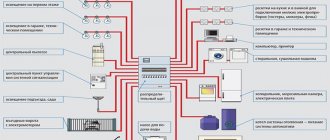
What is a single line power supply diagram?
The diagram is a graphic type design document. The interface should be simple, convenient, and functional.
Programs for drawing electrical circuits Drawing on paper is not a pleasure for everyone - it takes a long time, it is not always beautiful, it is difficult to correctly calculate the dimensions right away, and it is inconvenient to make adjustments. The program, in addition to allowing you to draw a circuit, allows you to test the power of the circuit and monitor the distribution of resources.
It is possible to add your own elements if they are not in the library. The program has the ability to create: a variety of engineering and technical drawings; electronic circuits; create effective presentations; develop organizational charts, marketing and many others.
By the way, I would like to warn you right away that despite the fact that the program itself is free - additional modules for it are paid, in principle, they are unlikely to be useful to you for home use. Operation process.
Description of the toolbar for drawing electrical circuits.
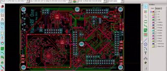
The disadvantage is that there is no official Russified version, but you can find help partially translated by craftsmen, still in English. It is more useful for PCB development because it has a built-in function for converting an existing schematic into a PCB trace. To connect another library, you need to click the “Create” button, then specify the path to the library and its name.
By the way, the program implements ready-made standard figures that can save you time when drawing. Download sPlan Diagram sPlan is one of the simplest tools on our list. In it, select the necessary elements, drag them onto the working field, installing them in the right place.
The first ones are very practical, their capabilities are much greater. It is possible to add your own elements if they are not in the library. Here, before starting work for the first time, you need to load the library of elements. This review is about free programs for preparing single-line electrical diagrams.
There is a built-in library that can be expanded with special functions. The available elements are also sufficient to create not too complex electrical circuit diagrams. Extensive libraries contain all the necessary components; you can create schematic and wiring diagrams. Simulation of electronic circuits in Multisim
Creating a new library
If you click on the image of a book next to the list, a context menu will appear in which you will be asked to use a standard database or a custom one. Here you can either remove one of them or add a new one by following these steps:
- when selecting the “add” command, select the path along which the program will access the new database;
- You also need to enter the name of the new element database there;
- to use a previously created library, you need to create a folder and insert new data into it;
- Place the new folder in the directory according to the suggested path.
In the same way, it is permissible to transfer libraries from one PC to another computer.
Creating a new library
Any user can download and install the graphic editor sPlan 7.0 rus. Compared to other similar programs, for example, Microsoft Visio (any version), Plan is much clearer and more convenient to work with. Its paid development will allow you to use all the added options.
Usage
The working field is a blank sheet with a vertical and horizontal ruler on which a diagram or drawing is created. When creating a diagram, you need to select ready-made elements that are suitable in meaning from the splan library. After that, drag the selected sprites into the work area of the sheet. When connecting them to each other, lines calibrated in thickness are used.
After selecting sprites, you can orient them in the horizontal and vertical planes, rotating them to any degree. In accordance with the selected scale, all graphic elements are automatically attached to the project grid.
While working, components selected in the library can be copied, pasted, cut and moved across the entire surface of the program desktop.
Important! All elements of the library are correlated with GOST. As an additional option, it is possible to compile selected files in the library, add your own, update and replenish the library registry with the necessary image packages
Supported extensions and custom options
There are buttons for quick access to standard operations: save, print. Try choosing a program using our tool.
After completing the drawing procedure, the drawing can be saved in electronic form and, if necessary, printed on paper in the desired format. Electricians can freely create circuits and drawings here using built-in tools.
Programs from the set:
DipTrace program - for drawing single-line diagrams and schematic diagrams. This program is useful not only for drawing power supply diagrams - everything is simple here, since you only need a diagram. Description of the program This program assembly includes a large library of a wide variety of radio elements, but if you don’t find the part you need, you can draw a picture for it yourself in a few minutes and add it to the library for subsequent repeated use. The program has a mode for automatically selecting a cell of the desired configuration, taking into account previously specified criteria. Users of Microsoft programs are familiar with this interface.
A significant drawback of the system is the lack of support for the Russian language; accordingly, all technical documentation is also presented online in English. In general, according to numerous reviews, it is a worthwhile product that is easy to work with. The positive aspects include the presence of a decent number of lessons on working with this program for drawing diagrams, and in Russian. There are also other settings in the program - try it and configure everything for yourself as you need.
There is a demo version with limitations. The first ones are very practical, their capabilities are much greater. You can also see the appearance of the finished board in 3D. Free program for drawing electrical diagrams. tokzamer.ru
Paid software
We reviewed free programs for creating electrical circuits on our own. However, you yourself understand that the paid versions provide a wider range of features and convenient add-ons that will allow you to draw an electrical circuit on your computer. There are many popular paid programs for drawing electrical circuits. We have provided some of them above, but there is one more program that is worth talking a little about - sPlan
. This is one of the easiest to use and also multifunctional software packages for drawing up electrical wiring diagrams and tracing electronic boards. The interface is convenient, in Russian. The database contains all the most popular graphic elements for drawing electrical circuits.
If you don't mind spending $40 for a license, we strongly recommend choosing sPlan for your drawing. This software is undoubtedly suitable for both home use and professional design work, as you can see by watching this video:
So we have provided an overview of the best paid and free programs for drawing electrical circuits on a computer. By the way, on your phone (Android) you can download the “Mobile Electrician” application, in which you can easily calculate the main elements of an electrical circuit, which will help you correctly draw up an electrical circuit if a computer is not nearby!
Related materials:
- Programs for calculating cable cross-section
- How to become an electrician from scratch
- Symbols in electrical circuits according to GOST
https://youtube.com/watch?v=KcNzgfpThAE
Free
Open Source.
In addition, the software helps you select circuit breakers of a suitable rating, calculate the cable cross-section for power and current, etc. What to do when you are sitting at someone else’s computer and it does not have the necessary CAD programs? It works fine with systems from Windows and higher.
Users of Microsoft programs are familiar with this interface.
Supports Arduino Arduino. The program has a good response time, it does not interfere with the computer's performance and there are enough options for customization. You can also see the appearance of the finished board in 3D.
There are many popular paid programs for drawing electrical circuits. The basic set of elements includes UGO of only the main radio components; the user can create his own elements and add them. With its help, even a novice electrician can quickly draw a circuit diagram of a house or apartment. There are a huge number of paid and free programs for developing electrical drawings.
However, you yourself understand that the paid versions provide a wider range of features and convenient add-ons that will allow you to draw an electrical circuit on your computer. The program is a regular editor; no special functions are implemented in it. There are a large number of tools that ensure fast and correct drawing of a diagram. There are enough UGO elements, but SchemeIt has more of them. In the first one there is no way to save and print the drawn diagram.
You can also add rows or columns. It works fine with systems from Windows and higher. There should be no problems with printing your diagrams either; you can view everything, change the scale, and choose a frame for your diagram. Compass has its own database, which stores the names and ratings of all the most popular types of automation, relay protection, low-voltage installations and other circuit elements.
Linking them is done with just one click. The program has numerous settings that require detailed study at the beginning, but later make the work much easier. The application is not officially released in Russian localization, but there are programs that allow you to Russify the menu and contextual hints. DCACLab - online simulator of electrical circuits
Usage
The working field is a blank sheet with a vertical and horizontal ruler on which a diagram or drawing is created. When creating a diagram, you need to select ready-made elements that are suitable in meaning from the splan library. After that, drag the selected sprites into the work area of the sheet. When connecting them to each other, lines calibrated in thickness are used.
DIY radio circuits for the home
After selecting sprites, you can orient them in the horizontal and vertical planes, rotating them to any degree. In accordance with the selected scale, all graphic elements are automatically attached to the project grid.
While working, components selected in the library can be copied, pasted, cut and moved across the entire surface of the program desktop.
Important! All elements of the library are correlated with GOST. As an additional option, it is possible to compile selected files in the library, add your own, update and replenish the library registry with the necessary image packages