Resonance effect
A striking example of the mechanical class of resonators is the spring pendulum. Professor from the Massachusetts Institute of Technology (in America), V. Levin, focuses the attention of his students on the fact that resonance is an effect associated with an increase in amplitude. An installation is used to demonstrate the phenomenon. It consists of the following components:
- electric motor;
- a mechanism that turns rotation into reciprocating motion;
- LATR – laboratory autotransformer;
- copper wire spring with a set of weights;
- spring guide.
The direction of spring oscillation is vertical. The rotation of the motor shaft causes the spring to oscillate. Using an autotransformer, it is possible to regulate the voltage. The adjustment allows you to vary the frequency of rotation of the shaft and oscillations of the pendulum. When the shaft rotation speed changes, the amplitude of the reciprocating motion remains unchanged.
Before the experiment, the elongation of the copper spring under the action of weights is measured (to estimate the resonant frequency of the spring). Changing the speed of rotation of the shaft causes the amplitude of oscillation of the end of the spring with the load to change. The amplitude increases and at the 1st hertz of frequency it becomes maximum (~30 cm).
Important! With a further increase in the shaft rotation speed, the amplitude of the end of the spring begins to decrease. This means that resonance has passed. If you reduce the voltage, and with it the engine speed, you can again observe the effect of resonance oscillations of the spring.
Spring pendulum
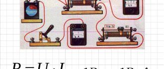
The quality factor of the spring Q is defined as the ratio of the oscillation amplitude of the spring Apr to the oscillation amplitude of the driving force Aavs. In this case, Q = Apr/Avs = 30/5 = 6, where Avs = 5.
Notes from a programmer
Oddly enough, in inductors we are primarily interested in inductance. Measuring inductance is not difficult. Ready-made RLC meters are inexpensive. If you don’t have an RLC meter, but you have an oscilloscope, the inductance can be determined using it. Also, a normal antenna analyzer can easily measure both inductance and capacitance. But inductors have at least two more important properties - their own resonance frequency and quality factor. Let's look at why these properties are important and how to measure them.
The essence of the problem
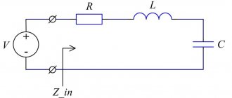
Inductors that exist in the real world can be described using the following model:
Here L is the inductance of the coil. The coil is wound by a certain conductor, and the real conductor has non-zero losses. The resistor Rs (also known as ESR, equivalent series resistance) reflects these losses. Capacitor Cp is the parasitic capacitance between the turns of the coil.
It can be seen that the inductance L and the capacitor Cp form a parallel oscillatory circuit. This circuit has a resonant frequency. This is called frequency of the coil . Below this frequency the coil behaves like a coil. However, higher up it starts to behave more like a capacitor. By determining the frequency of its own resonance, we will understand at what frequencies the coil can be used.
Rs is complex in nature, and working with it directly is inconvenient. Therefore, instead of talking about Rs, they talk about quality factor (quality factor or Q). Quality factor is a dimensionless quantity that characterizes the rate of decay of oscillations in an oscillatory system. The larger Q, the less attenuation.
For inductors, the quality factor is defined as the ratio of reactance to Rs:
Q = Xl / Rs
Reactance is a function of frequency. Rs actually also depends on frequency. In the ham radio world we usually talk about Q at the coil's operating frequencies. It is assumed that in this frequency range the quality factor changes insignificantly.
It is worth mentioning that there is a distinction between unloaded Q and loaded Q. For the purposes of this article, quality factor refers exclusively to idle quality factor. Loaded quality factor occurs when a coil is placed in a specific electrical circuit.
Subject
Let's try to determine the frequency of its own resonance and the quality factor of such a coil:
The coil is wound with MGTF wire with a cross-sectional area of 0.35 sq. mm on a PVC pipe with an outer diameter of 25 mm. For a forced step, I wound two parallel wires. Then one wire was gradually unwound, and the second was fixed with varnish. The winding length was 30 mm, the inductance was 2 μH.
This winding method was used in order to obtain a not very shameful quality factor. Through years of experimentation, radio amateurs have developed good practices to maximize the quality factor. Basic recommendations:
- A thick conductor is preferable to a thin one;
- Any dielectric used as a coil frame or conductor insulator reduces the quality factor;
- Charles Michaels, W7XC (SK) recommends a length to diameter (L/D) ratio of no more than 2:1 for air dielectric coils. Here we are talking about winding turn to turn;
- If the reel is wound on a frame, it is recommended L/D = 1:1;
- Tom Rauch, W8JI recommends using a turn spacing equal to the conductor thickness and an L/D of 1 to 4;
Some details can be found in Chapter 9 of ON4UN's Low Band DXing, 5th Edition, section 3.7.2 Making or Buying High-Q Loading Coils. I note that simply following these tips is not enough. If your goal is to get the highest quality factor possible, you need to take specific available materials, wind the coils and measure.
In fact, I wound five spools in five different ways. The one above had the maximum quality factor.
Looking for our own resonance
To determine the frequency of its own resonance, it was decided to use a spectrum analyzer. An oscilloscope with a signal generator, or an RTL-SDR with a noise generator, would work just as well. But a spectrum analyzer is more convenient.
To connect the coil between the tracking generator and the analyzer input, the following device was used:
The shields of the BNC connectors are interconnected, and the wires go to the banana connectors. The coil is connected to these connectors.
As a result, we get the following frequency response:
We have frequencies from 1 to 201 MHz, the horizontal division price is 20 MHz. The self-resonance, according to the graph, occurred somewhere at 150 MHz. Below, the signal attenuation increases with increasing frequency. This is how a reel is supposed to work. Above that, the attenuation decreases with increasing frequency. This is the behavior of a capacitor.
What conclusions can be drawn from this? The coil can be used at frequencies somewhere up to 37 MHz. At frequencies approaching the natural resonance frequency, coils cannot be used. The reason is that the quality factor decreases as it approaches its own resonance frequency. At the natural resonance frequency, the quality factor is zero. It is recommended to use coils at frequencies 4+ times lower than their own resonance frequency.
Determining the quality factor
To determine the quality factor, we will use the approach from the article Fixture for Measuring Inductor Q with your Antenna Analyzer [PDF], written by Phil Salas, AD5X. According to the instructions from the article, the following device was made:
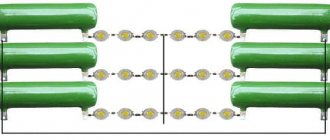
The idea is quite simple. The antenna analyzer is connected to the BNC connector, and the coil is connected to the banana connectors. In the first position of the toggle switch, the antenna analyzer measures the equivalent load of 50 ohms. For the equivalent load, 20 1 kOhm ± 1% resistors connected in parallel were used. In the second position, a series oscillatory circuit formed by the same 50 Ohm resistor, the measured coil and the KPI is measured.
At the resonant frequency, the series LC circuit is a short circuit, and we will see a net resistance of about 50 ohms:
In this case (first graph), the resonance fell at 9.3185 MHz. The antenna analyzer sees 50.4 ohms. Switch the toggle switch to another position. We see the resistance of the resistor without a circuit. It was 49.8 Ohms (second graph). There is also a slight reactivity at 0.4j. We will neglect it, since it is just:
>>> from math import pi >>> F = 9_318_500 >>> 0.4/(2*pi*F) 6.83178378888857e-09
... 6.8 nH, almost 300 times less than the measured 2 μH.
Look what happens. With the loop it was 50.4 ohms, and without the loop it was 49.8 ohms. The 0.6 ohm difference includes the Rs of the coil as well as the capacitor losses. But capacitors have a significantly higher quality factor (> 1000) than coils. Therefore, the difference of 0.6 Ohm is mainly due to the Rs coil.
Now we have everything we need to calculate the quality factor:
>>> from math import pi >>> F = 9_318_500 >>> L = 2.0/1000/1000 >>> Rs = 50.4 - 49.8 >>> Xl = 2*pi*F*L >>> Q = Xl/ Rs >>> Q 195.16620761650944
A quality factor of about 200 is a good result. Conventional commercial coils for through installation have a quality factor of around 100. It is not surprising that experienced radio amateurs prefer to wind the coils themselves. A random homemade coil of copper wire will already have a quality factor of about 100-150. According to Low Band DXing, with some practice you can easily make ~400 Q coils. Various sources give Q from 800 to 1000 as a ceiling.
Homework: Wind up a coil with a larger inductance, about 70 µH. For such a coil you will need a frame of about 70 mm and 30 turns of enameled wire with a diameter of 0.9 mm. How did Rs come out? Where does the self-resonance frequency fall? Compare with the results above.
An attentive reader may wonder why the resistor value was chosen to be 50 Ohms? This was done only for the reason that the measurement error of the antenna analyzer with such resistance is minimal. In theory, any other resistance can be used with the same success, as long as it is purely active.
Conclusion
Let's say we soldered a generator or filter and it doesn't work as expected. The reason may lie in the coils' own resonance. Are there too many losses in the matching device? The reason may be the low quality factor of the components. We now have a better chance of correctly diagnosing such problems, or better yet, avoiding them altogether.
Addition: We measure the parameters of quartz resonators
Tags: Electronics.
Definition of an Oscillatory Circuit
Rotation speed: formula
Resonance phenomena noted in electrical engineering are clearly expressed in the circuits of oscillatory circuits (OC). Such designs are elementary systems capable of carrying out free oscillations of an electromagnetic nature. The CC itself in the circuit consists of the following elements:
- capacitor;
- inductors;
- current source.
Attention! The terminals of the circuit elements can be connected to each other in parallel or in series. It all depends on what result you want to achieve from resonance in the CC.
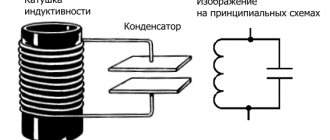
Oscillating circuit LC
Oscillatory circuit
- an electrical circuit in which oscillations can occur with a frequency determined by the parameters of the circuit.
The simplest oscillatory circuit consists of a capacitor and an inductor connected in parallel or in series.
— Capacitor C
– reactive element.
Has the ability to accumulate and release electrical energy. — Inductor L
is a reactive element. Has the ability to accumulate and release magnetic energy.
Let's consider how free electrical oscillations arise and are maintained in a parallel LC
.
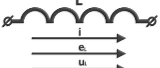
Basic properties of inductance
— The current flowing in the inductor creates a magnetic field with energy. — A change in current in a coil causes a change in the magnetic flux in its turns, creating an EMF in them that prevents a change in current and magnetic flux.
The nature of electromagnetic oscillations in the circuit
Period of free oscillations of the LC
can be described as follows:
If a capacitor with capacity C
charged to voltage
U
, the potential energy of its charge will be.
If you connect an inductor L
, a capacitor discharge current will flow through the circuit, creating a magnetic field in the coil.
An external magnetic flux will create an EMF in the direction opposite to the current in the coil, which will prevent the current from increasing in each turn, so the capacitor will not discharge instantly, but after a time t
1, which is determined by the inductance of the coil and the capacitance of the capacitor based on
t
1 =.
After time t
1, when the capacitor is discharged to zero, the current in the coil and the magnetic energy will be maximum.
The magnetic energy accumulated by the coil at this moment will be. In an ideal consideration, with complete absence of losses in the circuit, EC
will be equal to
EL
. Thus, the electrical energy of the capacitor will be converted into magnetic energy of the coil.
Further, a change (decrease from the maximum) of the magnetic flux of the accumulated energy of the coil will create an EMF in it, which will continue the current in the same direction and the process of charging the capacitor with induced current will begin. Decreasing from maximum to zero over time t
2 =
t
1, it will recharge the capacitor from zero to maximum negative value (
-U
). So the magnetic energy of the coil will be converted into electrical energy of the capacitor.
Described intervals t
1 and
t
2 will be half the period of complete oscillation in the circuit.
In the second half, the processes are similar, only the capacitor will discharge from a negative value, and the current and magnetic flux will change direction. Magnetic energy will again accumulate in the coil during time t
3, changing the polarity of the poles.
During the final stage of oscillation ( t
4), the accumulated magnetic energy of the coil will charge the capacitor to the initial value
U
(in the absence of losses) and the oscillation process will repeat.
In reality, in the presence of energy losses on the active resistance of the conductors, phase and magnetic losses, the oscillations will be damped in amplitude. Time t
1 +
t
2 +
t
3 +
t
4 will be the oscillation period.
Frequency of free oscillations of the circuit ƒ = 1 / T
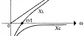
The frequency of free oscillations is the resonance frequency of the circuit at which the inductance reactance XL=2πfL
equal to the reactance of the capacitance
XC=1/(2πfC)
.
Calculation of the resonance frequency of the LC circuit:
A simple online calculator is provided to calculate the resonant frequency of an oscillating circuit.
You need to enter the values and click in the table. When switching multipliers, the result is automatically recalculated.
Top
Frequency calculation:
| Resonance frequency of the LC oscillating circuit. ƒ = 1/(2π√(LC)) |
Capacity calculation:
| Capacitance for the oscillating circuit LC C = 1/(4𲃲L) |
Inductance calculation:
| Inductance for the oscillating circuit LC L = 1/(4𲃲C) |
Similar pages with calculations:
Calculate impedance.
Calculate reactance.
Calculate reactive power and compensation.
Connecting to the inductive coil circuit
Current frequency
The inclusion of an inductor in the capacitive circuit immediately turns it into a CC. Depending on the connection diagram, there are two types of class 1 CCs: parallel and serial.
Parallel QC
In this circuit, capacitor C is connected to coil L in parallel. If a charged capacitor is connected to a coil, the energy stored in it will be transferred to it. A current will flow through the inductive coil L, causing an electromotive force (EMF).
The self-induction emf L will be aimed at reducing the current in the parallel circuit. The current created by this EMF and the discharge current of the capacitor are initially identical, and their total value is zero. The capacitor will transfer its energy Ec to the coil and will be completely discharged. The inductance, having received the maximum magnetic energy EL, will begin to charge the capacitor with a voltage of a different polarity. When all the energy from the inductance goes into the capacitor, the capacitor will be fully charged. Oscillations appear in the circuit; such a circuit is called an oscillatory circuit.
Parallel QC
For your information. If there were no losses in such a circuit, then such oscillations would never begin to fade. In practice, the duration of the process depends on the energy loss. The greater the losses, the shorter the duration of the oscillations.
Parallel connection of C and L causes current resonance. This means that the currents passing through C and L are higher in value than the current through the circuit itself by a specific number of times. This number is called the quality factor Q. Both currents (capacitive and inductive) remain inside the circuit because they are in antiphase, and their mutual compensation occurs.
It is worth noting! At fres, the value of R KK tends to infinity.
Sequential QC
In this circuit, a coil and a capacitor are connected in series with each other.
Sequential QC
In such a circuit, voltage resonance occurs, R of the circuit tends to zero in the event of the formation of a resonant frequency (fres). This allows a similar resonance system to be used as a filter.
Operating principle of the oscillating circuit
Let's look at an example where we first charge the capacitor and complete the circuit. After this, a sinusoidal electric current begins to flow in the circuit. The capacitor is discharged through the coil. In a coil, when current flows through it, a self-inductive emf , directed in the direction opposite to the capacitor current.
Having completely discharged, the capacitor, thanks to the energy of the EMF of the coil, which at this moment will be maximum, will begin to charge again, but only in reverse polarity.
The oscillations that occur in the circuit are free damped oscillations. That is, without additional energy supply, oscillations in any real oscillatory circuit will sooner or later stop, like any oscillations in nature.
This is due to the fact that the circuit consists of real materials (capacitor, coil, wires) that have such a property as electrical resistance, and energy losses in a real oscillatory circuit are inevitable. Otherwise, this simple device could become a perpetual motion machine, the existence of which, as we know, is impossible.
Another important characteristic of an LC circuit is the quality factor Q. The quality factor determines the amplitude of the resonance and shows how many times the energy reserves in the circuit exceed the energy losses during one oscillation period. The higher the quality factor of the system, the slower the oscillations will decay.
Resonance frequency
When an alternating voltage with a varying frequency is applied to two CCs (parallel and series) their reactances C and L will change. Changes occur as follows:
- with increasing f, the capacitive reactance decreases and the inductive reactance increases;
- as f decreases, capacitive reactance increases and inductive reactance decreases.
Resonance - what is it?
The frequency at which the reactances of both circuit elements are equal is called resonant.
Important! At fres, the resistance of the parallel CC will be maximum, and the resistance of the serial CC will be minimal.
The resonant frequency formula is:
fres = 1/2π*√L*C,
Where:
- L – inductance, H;
- C – capacity, F.
By substituting the known values of capacitance and inductance into the formula for the resonant frequency of an oscillatory circuit of any configuration, this parameter can be calculated.
To determine the oscillation period of the CC and the resonance frequency, you can use the online calculator on the corresponding portal on the network. The professional program has a simple interface.
An example of the interface of an online LC circuit calculator
Radio amateur
Practical calculation of series or parallel LC circuit.
Good afternoon, dear radio amateurs! Today we will look at the procedure for calculating an LC circuit .
Some of you may ask, why the hell do we need this? Well, firstly, extra knowledge never hurts, and secondly, there are times in life when you may need knowledge of these calculations. For example, many beginning radio amateurs (naturally, mostly young) are keen on assembling so-called “bugs” - devices that allow you to listen to something from a distance. Of course, I am sure that this is done without any bad (even dirty) thoughts of eavesdropping on someone, but for good purposes. For example, they install a “bug” in the room with the baby, and listen to the broadcast receiver to see if he has woken up. All “radio bug” schemes operate at a certain frequency, but what to do when this frequency does not suit you. This is where knowledge of the article below will come to your aid.
LC oscillatory circuits are used in almost any equipment operating at radio frequencies. As is known from a physics course, an oscillatory circuit consists of an inductor and a capacitor (capacitance), which can be connected in parallel ( parallel circuit ) or in series ( series circuit ), as in Fig. 1:
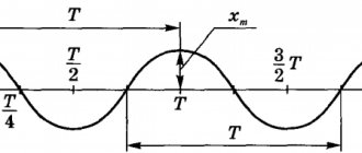
The reactances of inductance and capacitance are known to depend on the frequency of alternating current. As frequency increases, inductance reactance increases and capacitance reactance decreases. As the frequency decreases, on the contrary, the inductive reactance decreases and the capacitive reactance increases. Thus, for each circuit there is a certain resonance frequency at which the inductive and capacitive reactances are equal. At the moment of resonance, the amplitude of the alternating voltage on a parallel circuit sharply increases or the amplitude of the current on a series circuit sharply increases. Figure 2 shows a graph of voltage on a parallel circuit or current on a series circuit versus frequency:
At the resonance frequency these quantities have their maximum value. And the bandwidth of the circuit is determined at a level of 0.7 of the maximum amplitude that exists at the resonance frequency.
Now let's move on to practice. Suppose we need to make a parallel circuit that has a resonance at a frequency of 1 MHz. First of all, you need to make a preliminary calculation of such a circuit. That is, determine the required capacitance of the capacitor and the inductance of the coil. For preliminary calculation there is a simplified formula:
L=(159.1/F)2/C where: L – coil inductance in µH; C is the capacitance of the capacitor in pF; F – frequency in MHz
Let's set a frequency of 1 MHz and a capacitance of, for example, 1000 pF. We get:
L=(159.1/1)2 /1000 = 25 µH
Thus, if we want a circuit with a frequency of 1 MHz, then we need a 1000 pF capacitor and a 25 μH inductor. You can select a capacitor, but you need to make the inductance yourself.
You can calculate the number of turns for a coil without a core using the following formula:
N=32 *√(L/D) where: N – required number of turns; L – specified inductance in µH; D is the diameter of the frame in mm on which the coil is supposed to be wound.
Suppose the frame diameter is 5 mm, then:
N=32*√(25/5) = 72 turns.
This formula is approximate; it does not take into account the coil’s own interturn capacitance. The formula serves to pre-calculate the coil parameters, which are then adjusted when tuning the circuit.
In amateur radio practice, coils with tuning ferrite cores having a length of 12-14 mm and a diameter of 2.5 - 3 mm are more often used. Such cores, for example, are used in the circuits of televisions and receivers. To preliminary calculate the number of turns for such a core, there is another approximate formula:
N=8.5*√L , substitute the values for our circuit N=8.5*√25 = 43 turns . That is, in this case, you will not need to wind 43 turns of wire onto the coil.
Application of oscillatory circuits
A detailed calculation of the oscillatory circuit allows you to accurately select the size of the required CC elements. This allows them to be used in electronic circuits in the form:
- frequency filters - in radio receivers, signal generators, converters and rectifiers;
- oscillatory circuits - for isolating and tuning a broadcast station to a specific frequency;
- power resonance filters – for generating a sinusoidal voltage.
On civil aviation aircraft, CC is used in generator frequency control units.
Calculation of stretching capacitors of the tuning circuit.
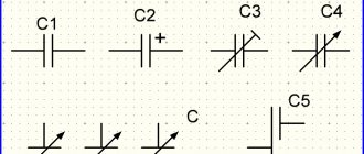
How to drive the tuning limits of a variable capacitor (VCA) in an oscillatory LC circuit into the desired frequency range. Online calculator of capacitances of stretch capacitors.“In the process of designing signal generators and master oscillators of transmitters, radio amateurs often encounter difficulties in purchasing a variable capacitor with the required limits for changing the capacitance. I offer readers a simple way to calculate the capacitances of additional capacitors C1 and C2 (see figure), the inclusion of which in the oscillatory circuit of the generator allows you to obtain the desired tuning range.”
Fig. 1 General diagram of an oscillatory circuit with stretching capacitors
This is how a very useful article begins, published in Radio magazine, 1992, No. 11, p. 23, under the authorship of S. Biryukov. Further there are equations and rather cumbersome final formulas for calculating the values of stretching capacitors C1 and C2, as well as a practical example of calculating a circuit with KPI. For those who want to master the theoretical part of the process, I recommend turning to the article in the magazine, and for practitioners I will give a simple table that allows you to calculate the values of the required capacitors online without unnecessary stress, a calculator and wooden abacus. In addition, the respected author’s formulas do not take into account the capacity indicated in Fig. 1 - Skont. However, this capacitance is always present in a real device and is numerically equal to the sum of: the inductor’s own capacitance, the total capacitance of the radio elements connected to it, as well as the capacitance of the printed circuit or any other wiring conductors. And you have to try hard to ensure that the value of this total capacity falls within ten picofarads. Even with a fairly thoughtful installation, the value of Skont is usually 15...20 pF. In short, for maximum reliability of the final result, the size of this capacity must be taken into account!
CALCULATOR FOR CALCULATION OF STRETCHING CAPACITORS OF LC CIRCUIT.
It must be borne in mind that the selected values of the initial quantities must be correct. For example, this applies to the frequencies of the range, which should not be excessively wide for the selected KPI. It is important to ensure that the calculated nominal value of capacity C1 is greater than the value “maximum capacity of KPI taking into account C1, C2”. If this is not the case, then you must either reduce the inductance of the coil or reduce the width of the tuning range. There are other options for restrictions that the user can figure out on their own, using trial and error.
Well, using formulas as simple as calico underpants for calculating the series-parallel connection of capacitors, you can solve the inverse problem and see what the tuning band of the circuit will be when soldering into the circuit capacitors from the series available to the radio amateur.
CALCULATOR OF TUNING FREQUENCIES OF LC CIRCUIT WITH STRETCHING CAPACITORS.
This calculator is not influenced by the input data and will show the correct result for any values of the initial values.
Resonance amplitude
In a CC, when an alternating voltage is applied from an external source, two types of resonance and a sharp increase in two types of amplitude are observed: current amplitude and voltage amplitude.
Current amplitude
The current amplitude increases sharply with voltage resonance in the series circuit (series resonance). The source of alternating EMF is connected to a circuit where the series-connected elements L and C serve as the load.
In this case, the circuit includes resistances: active r and reactive x, equal to:
x = xL – xC.
Since for internal oscillations xL and xC are equal, then for the current supplied from the generator, at resonance (when the frequencies coincide) these values are also the same. Therefore x = 0. As a result, the total resistance of the circuit will consist of only a small active resistance. This results in maximum current.
Scheme (a) and resonance curves (b) for voltage resonance
Voltage amplitude
Current resonance (parallel resonance) is a condition for a sharp increase in voltage amplitude. The EMF source is connected outside the circuit and loaded by elements L and C connected in parallel. In this case, the resonance effect is affected by the internal resistance of the generator. The voltage amplitude on the circuit is maximum when the difference between the circuit voltage and the generator voltage is small. This is possible with small Ri.
Attention! Changing the generator frequency changes the current, and the voltage amplitude on the circuit does not lag behind the voltage on the generator. If, U = E - I*Ri, where E is the emf, I is the current, then at small Ri U = E.
Scheme (a) and resonance curves (b) for current resonance
The formula for determining the calculated resonant frequency for different oscillatory systems differs in the parameters included in it. Despite all the differences, the essence remains the same: the resonance effect occurs when the frequency of internal oscillations of the system and external influences become equal to each other.
Factors Affecting Coil Inductance
Several factors influence the inductance of a coil.
- Number of turns. A coil with more turns has higher inductance than a coil with fewer turns.
- Winding length. Two coils with the same number of turns but different winding lengths have different inductances. A longer coil has less inductance. This is due to the fact that the magnetic field of a less compact coil is weaker and it cannot concentrate well in a stretched coil.
- Coil diameter. Two tightly wound coils with the same number of turns and different diameters have different inductances. A coil with a larger diameter has greater inductance.
- Core. To increase the inductance, a core made of a material with high magnetic permeability is often inserted into the coil. Cores with higher permeability allow for higher inductance. Cores made of magnetic ceramics - ferrite, are often used in coils and transformers of various electronic devices, as they have very low eddy current losses.
Simplified equivalent circuit of a real inductor: R
w is the resistance of the winding and its terminals;
L
is the inductance of an ideal coil;
R
l - resistance due to losses in the core;
and C
w is the parasitic capacitance of the coil and its terminals.
Video
Coffee capsule Nescafe Dolce Gusto Cappuccino, 3 packs of 16 capsules
1305 ₽ More details
Coffee capsules Nescafe Dolce Gusto Cappuccino, 8 servings (16 capsules)
435 ₽ More details
Samsung Galaxy Note 9 smartphones
Free electrical oscillations in a parallel circuit.
Basic properties of inductance:
– The current flowing in the inductor creates a magnetic field with energy. – A change in current in a coil causes a change in the magnetic flux in its turns, creating an EMF in them that prevents a change in current and magnetic flux.
Period of free oscillations of the LC
can be described as follows:
If a capacitor with capacity C
charged to voltage
U
, the potential energy of its charge will be.
If you connect an inductor L
, its discharge current will flow through the circuit, creating a magnetic field in the coil.
The magnetic flux, increasing from zero, will create an EMF in the direction opposite to the current in the coil, which will prevent the current from increasing in the circuit, so the capacitor will not discharge instantly, but after a time t
1, which is determined by the inductance of the coil and the capacitance of the capacitor based on
t
1 =.
After time t
1, when the capacitor is discharged to zero, the current in the coil and the magnetic energy will be maximum.
The magnetic energy accumulated by the coil at this moment will be. In an ideal consideration, with complete absence of losses in the circuit, EC
will be equal to
EL
. Thus, the electrical energy of the capacitor will be converted into magnetic energy of the coil.
A change (decrease) in the magnetic flux of the accumulated energy of the coil will create an EMF in it, which will continue the current in the same direction and the process of charging the capacitor with induced current will begin. Decreasing from maximum to zero over time t
2 =
t
1, it will recharge the capacitor from zero to the maximum negative value (
-U
). So the magnetic energy of the coil will be converted into electrical energy of the capacitor.