Artificial lighting is the most important component of comfort. This is a necessary minimum, without which modern man cannot imagine his existence. It is clear that artificial light sources need to be controlled. Lighting control involves three functions:
- inclusion
- shutdown
- brightness control (dimming)
There are many devices to control lighting. In this article we will talk about the most common and necessary ones - switches and switches. But first, a little clarification: we are talking about electrical installation equipment for household use for hidden and open installation, designed to work in alternating current networks and designed for a voltage of 220-230V. These are the devices that are used in everyday life. They are also used in office and administrative buildings.
Buy switches, switches, open the product catalog.
How does a single-key switch work?
A household single-key switch is a familiar element of the environment.
Its main parts are:
- base with fastening elements;
- movable panel;
- contact group with moving and fixed contacts;
- decorative elements (usually made of plastic).
The main components of a single-key switch.
The principle of operation of any switch is similar - when exposed, it opens and closes an electrical circuit. But different devices do this in different ways, depending on the features of the device and functionality.
Design options
The design of light switches may vary in degree of protection (IPxx, where xx are two digits indicating the level of protection from solid objects and particles and from water). Depending on it, the area of application of the device is determined. Thus, switches with IP 21 are used only indoors, but with IP44 or 54 they can be mounted outside.
Device with degree of protection IP54.
There are also switches for surface mounting and built-in type. The first are mounted on a lining and used in conjunction with open wiring. The latter are mounted in a recess on the wall into which the socket box is built. This installation is used with hidden wiring and is more aesthetically pleasing. The likelihood of mechanical damage to devices is less, but the labor intensity of the installation work is much higher.
Overhead switch.
The switches also differ in the rated load (current or power) that the device can switch. The value indicated on the housing or in the specification must not be exceeded.
| Switch type | Device type | Load capacity of contacts, A |
| MAKEL Mimoza 12003 | Double key | 10 |
| Simon S27 | Button | 10 |
| Jilion 9533140 | Two-key pass-through | 10 |
| Bylectrica Praleska | Three-key key | 6 |
| Schneider Electric GSL000171 GLOSSA | Cross | 10 |
Connection rules and preparation for installation
According to the provisions of the PUE, connecting a single-key switch to any network is carried out only through a phase conductor break.
Installing it in a cross-section of the zero bus is strictly prohibited. Otherwise, there is a risk of receiving an electric shock when repairing a chandelier, for example.
Before connecting the switch to the linear conductors, you will need to thoroughly prepare for this event.
Preparatory procedures
Rules for the location of wiring
At the preparatory stage, the following operations are carried out:
- Select a location suitable for installing the device. The main requirements are convenience and safety.
- The connection diagram of the switch is drawn in all details.
- A set of tools and materials is being prepared, without which it is impossible to do during installation work.
The installation location is selected in full compliance with the requirements of current regulations, and when drawing up the connection diagram to the switch, the direction of connection must be taken into account.
There are arrows pointing inward and outward on the body at the bottom and top. They mean the entry points of the phase conductor coming from the linear machine and the output of its continuation.
If there are no arrows, you should be guided by other signs indicating where the switch is up and where it is down. The wire from the circuit breaker is always fed from below. For internal or external installation and subsequent connection to the network, you will need the following set of tools and materials:
- flat and Phillips screwdriver;
- mounting side cutters;
- installation box for hidden installation;
- socket box for open installation.
You should also prepare insulating tape and a set of additional fasteners.
When preparing the instrument, it is important to pay attention to one more important detail. To install the switch in a closed way, you will need a drill with a special drilling attachment, which experts call a “crown.”
Design and operation of a backlit switch
Many switches are now equipped with a backlight circuit. It performs several functions:
- allows you to locate the switch in the dark;
- serves as an indicator of the disconnected state of the switching device;
- in some cases, the glow indicates the integrity of the lighting circuit (and in the case of incandescent lamps, the serviceability of the light bulb).
The lighting circuit is assembled on a device, for which a very small current is enough to glow - a few milliamps. LEDs or miniature neon lamps are suitable for use in such conditions.
Backlight circuit and diagram of its operation.
From the connection diagram it can be seen that when the main switching device is turned off, a current flows through the LED, limited by the resistor and the resistance of the lamp. If the switch is closed, then the backlight circuit is bypassed and the LED does not light. If you turn off the lamp, there will be no glow either - the circuit is broken.
In the era of dominance of incandescent lamps, the backlight circuit did not have any effect on the operation of the circuit. When energy-saving and LED lamps have become widespread, even extremely low current flowing through the resistor and LED in some cases causes unpleasant flickering of the lamps. To combat this phenomenon, you need to bypass the lamp with a several kilo-ohm resistor or a capacitor.
Touch switch repair
The device operates by closing and opening the contacts of the electrical circuit. The switch may fail due to:
- Wear of the contact group.
- Hull destruction.
- Destruction of the terminal and place where the wires are fixed.
- Melting of the entire device.
Before troubleshooting, you need to stop the electricity supply by turning off the switch on the input panel. This will protect you from electric shock. Before repairing the switch, you need to install one light bulb in the lamp to check the functionality of the circuit.
The keys and decorative frames of the switches have small protrusions that allow you to pry the element with a flat screwdriver and remove it without damage.
The procedure consists of the following steps:
- Remove the top panel.
- Remove the decorative trim, if present.
- Check with the indicator whether there is voltage on the device.
- Loosen the internal fasteners.
- Disconnect the wires from the switch body.
- Place fuses on bare wires or make insulation using special tape.
The dismantled elements must be examined in detail to identify deformations, traces of poor contacts and other causes of malfunction.
Most often, the device fails due to burnt contacts. They can be simply cleaned using a small piece of sandpaper. You also need to check the functionality of the fixing screw, since quite often failure occurs due to a good clamping of the wires. If the integrity of the panel is compromised, this indicates that the switch has finally broken down and needs to be replaced.
Assemble the switch carefully, making sure that each wire is connected correctly. After this, the functionality of the device is checked.
Terminals for connecting wires
There are two main types of terminals for connecting conductors to a switching device:
- screw - the conductor core is clamped by tightening the screws;
- clamping (spring) - just insert the conductor, the spring-loaded platform will press it itself.
Spring terminals are more convenient and installation is faster. But screw ones are considered more reliable.
Device with spring terminals.
On the other hand, if the wiring is done with a cable with aluminum cores, you should remember the ductility of this metal. Screw terminals require periodic tightening, otherwise bad contacts and the corresponding consequences cannot be avoided. The spring ones will press the wire themselves.
The best three-key switches
This section presents multifunction switches with three keys.
BroadLink TC2-3 White
4.9
★★★★★
editorial assessment
96%
buyers recommend this product
A remote-controlled switch can operate lighting from anywhere in the world with an Internet connection and a Broadlink RM Pro remote control. The device is mounted like a regular switch and controlled by buttons on the panel or a wireless gateway via Wi-Fi.
It is possible to create one controlled system from several switches because Broadlink works on a modular principle.
The panel is made of tempered glass, and the interior is made of durable plastic. The device is equipped with 8 groups of timers, with which the user can set a schedule for turning on/off the lights. There is also a function that automatically turns on when you come home and turns off when you leave.
Advantages:
- The radio signal operates at a distance of up to 50 m;
- Supported voltage – 110-250 V;
- Quality materials;
- Laconic modern design;
- Free mobile application.
Flaws:
- Uneven lighting.
This stylish device will fit into absolutely any modern interior.
Three-key DeLumo
4.9
★★★★★
editorial assessment
95%
buyers recommend this product
This is not just a switch, but a radio remote control that transmits a signal to the power grid. The relay connects to light sources, lamps and even power supplies.
The switch does not need to be connected to wiring - it runs on a battery with a 7-year lifespan. The transmission range is 250 meters. The front glass panel is available in 25 colors.
Advantages:
- Small relay;
- Maximum switching power – 1000 Watt;
- Installation in any convenient place;
- Supports all types of lamps;
- Installation kit included.
Flaws:
- Small buttons.
The three-channel technological device works in conjunction with three single-channel radio relays, while taking up no more space than any classic switch.
Imex 70 Wide Ivory WSN 0326
4.8
★★★★★
editorial assessment
89%
buyers recommend this product
A simple but very reliable model in a matte case in a pleasant beige shade from a well-known manufacturer. LED backlighting on each key allows you to quickly find the switch. The smooth cover and switch buttons are very easy to care for.
Advantages:
- Quality materials;
- Discreet design;
- Quiet switching;
- Compact dimensions;
- Affordable price.
Flaws:
- The backlight may seem intrusive and bright.
This switch will not stand out on the wall thanks to its discreet design.
Markings on devices
Sometimes you can see symbols on the front of the switch. They indicate the area of application of the device.
Device with marking of on and off positions.
Conventional light switches equipped with keys may be labeled I and O to indicate the on and off positions.
Device with a key symbol.
Also, conventional devices that work only to open or close an electrical circuit can be marked with a key symbol.
Push-button switch with bell symbol.
Push-button switches without fixing in one of the positions can be used both as bell buttons and as switches in a lighting system assembled on the basis of pulse relays. Such devices are marked in the form of a bell (bell).
Pass-through switch of overhead design with bidirectional arrows.
Pass-through switch with staircase symbol for indoor installation.
Pass-through type devices can be marked with symbols in the form of a bidirectional arrow or in the form of a flight of stairs.
Some manufacturers have keys with space for inserting a character. But in general, there is no single standard for marking devices, just as there is no obligation to put symbols on the front. Therefore, many manufacturers, both little-known and world leaders in the electrical engineering market, often neglect the application of markings.
How to install a gateway
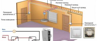
Nowadays, it has become very popular to install switches that allow you to turn off one group from different parts of the room. Let's look at how to properly connect pass-through light switches:
Photo - connection diagram for pass-through switch
- The diagram takes into account the connection box, since without it it will be difficult to make a connection;
- You need to bring the phase neutral wire into the junction box and connect it to the lamp neutral. The central phase cable is connected to the input contact of one of the switches to choose from;
- After this, two switched contacts of one switch must be connected to similar terminals of the second;
- Now, after connecting the switches, the phase from one (to which it was previously connected) is transferred to the second. Everything is placed in a box and closed.
Photo - operating principle of the pass-through model
Be sure to insulate all contacts, otherwise they will short out. Many experts recommend using soldered contacts - it is more reliable and durable than electrical tape.
Design of various types of switches
The purpose of any switching device is to turn the light on and off when acted upon. But the required impact may vary depending on the design.
Key
This design is familiar to everyone. A regular switch, in one position the contacts are closed and the light is on, in the other they are open and the light is off. They come in single-key, two-key and three-key versions.
A device with two keys.
The design of the key-type switch has hardly changed over many years - behind the decorative plastic parts there is a movable panel that controls the contact group. All this is assembled on a supporting structure.
Button
The basis of such a switch is a button. There are two options for this device:
- With fixation . Works like a keyboard. When pressed for the first time, the button is locked in the on position. In the second case, it is pressed to the off position.
- No fixation . When pressed, the contacts close, when released, they open. Can be used for electric bells and impulse relay circuits.
The first type of devices is usually built into lamps. The second one is mounted on a vertical plane.
Cord (rope)
A rope-type switch (“puller”) is available either built into wall lamps or as a stand-alone device for controlling lighting in a room. It is controlled by a cord that must be pulled.
Rope switch device.
A rather complex mechanism works according to a simple algorithm - each manipulation of the rope changes the state of the contacts to the opposite:
- to turn on the light, you need to pull the cord once;
- turn off - pull a second time;
- turn it on again - a third time and so on in a circle.
Such a switch, with a certain degree of assumption, can be called a mechanical implementation of a pulse relay. In most cases, the contact group operates to make or break.
Turning
Rotary switches make and open contacts when the handle is turned. This is quite inconvenient, so such devices are now rarely used and only for design purposes.
Rotary device under "Retro".
This category also includes some types of modern switches combined with brightness controls (dimmers). To turn off, the handle must be turned towards the minimum brightness and tightened until it locks. To turn it on, turn the knob in the opposite direction.
Internal structure of a dimmer switch.
Acoustic
The acoustic switch responds to sound. The built-in microphone picks up sound and converts it into an electrical signal, which is then amplified, filtered, and compared with a set threshold.
Acoustic device for lighting control.
If the specified level is exceeded, a command is generated to turn on or turn off the load. This device is convenient if there is a person with limited mobility in the apartment . But the noise immunity of such devices leaves much to be desired - unauthorized operations from extraneous noise are possible.
Sensory
The device of the touch light switch is different in that to turn on the lighting you just need to touch the panel without applying any force to press. The main advantage is the ability to integrate additional functions, which is important when used in systems such as “Smart Home”. In other cases, it serves rather an aesthetic function for decorating rooms in the High-Tech style.
Touch switch.
Operating principle of the switch
How a switch-button works depends on the control method, although all types have the same principle: when the circuit is closed, the current passes from the source to the consumer and the light or equipment turns on, and when it is opened, the circuit opens and the device turns off. The difference lies in how the contacts are connected/disconnected.
Circuit switching using push-button devices is performed in one of three ways:
- pulse - when you press and hold the button, the circuit closes, after removing the load, the contacts open;
- according to the key principle - one press of a key connects the contacts, the next one disconnects the circuit;
- “push-button” type (popular in the USA) - such devices contain two buttons: when you press one button (“on”), the second (“off”) is pushed out, and vice versa.
Push-button elements without latching are called pulse elements, while keys and push-buttons are button-switches with latching. The first option is often used in door locks and control panels due to their small size and the impossibility of spontaneous activation (during operation, the button must be kept pressed at all times). Fixing switches are equipped with lighting and household appliances.
Difference in functionality
Switches even of the same type and design can perform different functions. In most cases, this difference is determined by the design of the contact group, but not always.
Key
An ordinary household electrical circuit breaker-closer, the most common type. Depending on the number of keys, it controls the corresponding number of contact groups.
Contact groups of "key" type switches.
The power side pins are usually combined.
Button
The principle of operation of a switch with a button differs only in the direction of action and, in some cases, in the absence of locking in the pressed position.
Contact group of a push-button device.
The functionality of the contacts is the same, but they are arranged a little differently and are indicated by a different symbol in the diagram.
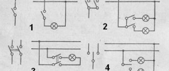
Passage
This type of switch is more of a switch. It is equipped with a changeover contact group - in one position one pair of contacts is closed, in the other - another. Such devices come in single-key and two-key versions.
Contact diagram for pass-through switch.
In appearance, it may not differ from a regular key (if there is no marking), but its internal diagram is usually applied on the back side. Available in single or double versions.
The back side of the pass-through apparatus.
Such devices are used in cases where it is necessary to organize independent lighting control from two or more points.
Cross
This switch has one key that controls two changeover groups of contacts connected in a special way.
Cross-type device contact diagram.
Such a device is used in conjunction with walk-throughs where it is necessary to control a load from three or more places.
Combined instruments
To increase the comfort of light control in an apartment, office or factory, devices have been created that combine several functions. For example, you can purchase:
- rotary switch with dimmer;
- pass-through switch with dimmer;
- other devices.
Devices based on microcontrollers have unlimited possibilities for combining functions. Such switches are used in Smart Home systems.
We recommend viewing.
There are many household lighting switches available for sale, differing in design, functionality, and appearance. With their help, you can organize a lighting system from simple to controlled from a smartphone. To do this, it is important to understand the capabilities and know the range of modern switching devices.
Connecting a two-key model
A standard two-button light switch is designed to control various lighting devices or multiple groups of one lamp from a single location. Most often they are used if the chandelier has more than 2 lamps (5.6). In this case, you need to know that two keys are used to control only two groups; if the lamp is divided into more of them, then you need to use a triple switch.
Photo - connecting a two-key model to a chandelier
How to connect a two-key light switch yourself:
- This model has three contacts - an input and two outputs. In this case, the phase from the distribution box is connected to the input contact, and the outputs are needed to control individual groups of the chandelier;
- You need to insert the phase wire of the network and its zero into the distribution box;
- First of all, all neutral conductors are connected to each other. The phase one is connected to the input of the electric light switch;
- It also has wires for each group of lamps. They are most often separated by color coding. In order for each group to burn independently of the other, each must be connected to a separate phase wire. For example, yellow and gray cables: yellow is assigned to group 1, and gray to group 2;
- The neutral wire of the switch is connected to the zeros of the lamps and the network;
- All that remains is to isolate the conductors.
In this case, a double light switch can be connected so that when one group (main) is turned off, the second (additional) is also turned off, then the circuit will be slightly different. It is necessary to switch the device not each group separately, but both at once. The triple can be connected in a similar way. The main thing is that when the keys are turned off, the phase is disconnected, not the zero.
It is also very often necessary to connect the switch to a sconce lamp and socket. This greatly saves space in the room allocated for electrical outlets. Then the diagram looks like this:
- The socket is installed parallel to the supply wires. The phase corresponds to the network phase, and the zero corresponds to zero;
- The procedure for turning on the lamp does not change; we do everything as described above.
In this way, you can install a model produced by Legrand, Viko, UAZ or any others.
Connection to a chandelier or lamp
In a lamp or chandelier, terminal blocks are usually used for connection. Place the wires of the cable coming from the junction box onto them according to the color marking.
A factory-made lamp must have cores of exactly the color specified in the rules. Phase - a gray or dark-colored conductor should go to the central contact of the lamp, and zero - blue to the light bulb base itself.
The yellow-green ground connection can be attached either to the terminal or directly under the screw on the housing.
Sources - https://cable.ru, Kabel.RF
Scope of application of push-button switches
Most often, push-button switches are used in household appliances and mobile lighting devices. They are included in the package of control panels, cabinets in stationary installations, and panels. Special operating conditions for push-button switches are not needed, because during operation the temperature range can be from - 60 to + 40 degrees with relative humidity up to 100%. They can be used for outdoor and indoor installation, in chemically active environments, explosive areas, in the oil and gas industry and other industries.
Design Features of Push Button Switches
In terms of variety of colors, designs and shapes, these controls are very little inferior to key switches. If you wish, you can choose a model with or without backlighting, find products in modern, retro style, and so on.
Push-button switches of the usual design are usually manufactured in plastic cases, due to which these products have a low cost. If you handle them carefully, they can last quite a long time, withstanding many thousands of switching cycles. For greater user convenience, the push-button switch with latching is supplemented with a light indicator indicating the state of this device (off or on). If similar products will be used in difficult conditions, it is recommended to purchase them in a vandal-proof design, because they have excellent mechanical strength.
Equipment Features
The KE push-button switch is used in almost all areas of industry. Such equipment is purchased both by mechanics for machine tools and by electricians for control panels. Products in this series are used on mobile installations or on stationary equipment.
This device includes:
- unified contact elements;
- control device;
- fasteners.
In a switch, the drive is the device responsible for the tightness of the connection and the pusher. It is equipped with a warning lamp to notify personnel of the operating condition. The NO/NC contacts are not connected to each other. When you press the working pusher, the traverse moves, which opens/closes the contact.
Before installing the product, you need to remove the front ring and tighten the slotted nut until it stops so that the switch does not rotate. The button is inserted into the hole with the back side so that there is a ring antenna there. Then, holding the device, you need to screw the front ring along the axis until it stops, run the power wires and connect it to the equipment.
Installation of connections for a two-gang switch in a distribution box
The following cables can enter the junction or distribution box:
- power cable from the machine in the panel
- cable going down to the switch
- one (if you have a chandelier with two lighting circuits) or two cables (if the light points are in different places) to the outgoing lamps
To avoid confusion, follow the following order:
First of all, connect all neutral conductors. They are usually blue. Zero does not pass through the two-key switch and goes directly from the panel to the lamp, through the connections in the distribution box.
All stripped wires can be connected using Wago quick-release terminals.
Although everyone has a different attitude towards them, they are an ideal option for lighting circuits with minimal loads.
Next in order is protective grounding. This is a yellow-green wire. If you do not have a grounding conductor in your apartment or the lamp body is insulated and the cable is two-core, then this connection will not be in the junction box.
It remains to connect the phase conductors. Here you need to be extremely careful. First, clamp the phase that comes from the power supply into the Vago terminal block. Then insert a wire into the same terminal that comes from the common phase contact of the two-key switch.
You should have 4 free, unconnected wires left. Two of them are the wiring that goes to the chandelier or sconce, and the other two wires are phases connected to the lower outgoing contacts of the two-key switch.
Take two more clamps and SEPARATELY connect these conductors through them. Thus, you will connect two lighting circuits to the lamps independently of each other.