Light-emitting diodes (also known as led) have been actively used for many years both in the production of televisions and as the main lighting of a house or apartment, but the question of how to properly connect LEDs is still relevant today.
Today there are a huge number of them, of varying power (super-bright Piranha), operating on constant voltage, which can be connected in three ways:
- Parallel.
- Consistently.
- Combined.
There are also specially designed circuits that allow you to connect the LED to a stationary 220V household network. Let's take a closer look at all the LED connection options, their advantages and disadvantages, as well as how to do it yourself.
Basic principles of connection
As mentioned earlier, the design of a light-emitting diode involves connecting them exclusively to a direct current source. However, since the working part of the LED is a semiconductor silicon crystal, it is very important to maintain polarity, otherwise the LED will not emit a luminous flux.
Each LED has technical documentation, which contains instructions and directions for correct connection. If there is no documentation, you can look at the LED markings. The marking will help you identify the manufacturer, and knowing the manufacturer, you can find the required datasheet, which contains information on the connection. Here, this is not a tricky piece of advice.
How to determine polarity?
There are only 3 ways to resolve the issue:
- Constructively . According to standards accepted throughout the world, on a regular LED (not SMD type), the long leg is always the “+” or the anode. For an LED to work, a positive half-wave must be supplied to it. And the short one is the cathode.
- Using a multimeter. To check, you need to set the device switch to the “Test” mode and install the red multimeter probe on the anode, and the black probe on the cathode. As a result, the LED should light up. If this does not happen, you need to change the polarity (black to the anode, and red to the cathode). If the result does not change, then the LED has failed (to establish a more accurate diagnosis, read how to check the LED).
- Visually . If you look closely at the LED, you can see 2 tips near the crystal. The larger one is the cathode, the smaller one is the anode.
We've sorted out the polarity, now we need to decide how to connect the LED to the network. For those who do not understand, read a detailed and interesting article on determining the polarity of an LED. In it we have collected all possible methods of checking, and even using a battery.
Installation features
To correctly connect spotlights, you need not only to choose the right circuit. It is necessary to follow a certain sequence of actions, which depends on the type of ceiling.
You just need to connect a few spotlights - and you have a beautiful interior
In suspended ceilings
Spotlights are usually installed with suspended or suspended ceilings. If the ceilings are suspended, all wires are laid in advance. They are attached to the ceiling without connecting to power, the lamps are placed and secured on pendants, then the wires are connected to them and the operation is checked.
Prepared for installation of suspended ceilings
Before installing suspended ceilings, turn off the power, remove the lamps and remove parts that may be damaged by temperature. After installing suspended ceilings, holes are cut in the material (the lamps are visible or can be felt), sealing rings are installed, and then the lamps are assembled.
In plasterboard ceilings
If the ceiling is made of plasterboard, you can proceed according to the same scheme, but the lamps must be installed after the ceiling has been plastered. That is, separate the wiring and leave the ends of the wiring hanging freely. To avoid problems with determining the location of lighting fixtures, it is necessary to draw a detailed plan indicating the exact distances from the walls and from each other. According to this plan, markings are made and holes are cut out using a drill with a crown of the appropriate size. Since there may be small movements - a few centimeters - when cutting the cable, leave a margin of 15-20 cm. This will be quite enough (but do not forget that the wires are attached to the main ceiling and they should extend 7-10 cm beyond the level of the drywall. If the ends turn out to be too long, you can always shorten them, but extending them is a big problem.
If you need to install a converter
There is a second way to connect spotlights to a plasterboard ceiling. It is used if there are few light sources - four to six pieces. The entire installation of spotlights along with wiring is done after the work on the ceiling has been completed. Before installation begins, the cable/cables from the junction box are led beyond the ceiling level. After finishing the puttying and sanding work, markings are made and holes are drilled. The cable is passed through them, bringing the ends out. Then the lamps themselves are installed.
Everything is simple, but this method cannot be called correct: the cables simply lie on the drywall, which definitely does not comply with fire safety standards. You can still turn a blind eye to this if the ceiling is concrete, the cable is non-flammable, the cross-section of the wire is not small, and the connection of the wires is done correctly.
Sequence of work in photo format
If the floors are wooden, the PUE requires installation in non-flammable all-metal trays (cable ducts) or metal pipes. You can install such wiring only before starting work on the ceiling. It is very undesirable to violate installation rules - wood, electricity, heat generation during operation... not the safest combination.
Connecting LEDs to 220V voltage
The first thing you need to know when connecting to a 220V network is that for a nominal glow, a current of 20 mA must pass through the LED, and the voltage drop across it should not exceed 2.2-3V. Based on this, it is necessary to calculate the value of the current-limiting resistor using the following formula:
in which 0.75 is the reliability coefficient of the led, U pit is the voltage of the power source, U pad is the voltage that drops across the light-emitting diode and creates the luminous flux, I is the rated current passing through it, and R is the nominal resistance for regulating the passing current After appropriate calculations, the resistance value should correspond to 30 kOhm.
However, do not forget that a large amount of heat will be generated at the resistance due to the voltage drop. For this reason, it is additionally necessary to calculate the power of this resistor using the formula:
For our case, U will be the difference between the supply voltage and the drop voltage across the LED. After appropriate calculations, to connect one LED, the resistance power should be 2W.
After determining the rating and power of the resistance, you can assemble a circuit to connect one LED to 220V. For its reliable operation, it is necessary to install an additional diode that will protect the light-emitting diode from breakdown when an amplitude voltage of 315V (220*√2) occurs at the LED terminals.
The circuit is practically not used, since very large losses occur in it due to heat generation in the resistance. Let's consider a more efficient connection diagram to 220 V:
In the diagram, as we can see, a reverse diode VD1 is installed, which passes both half-waves to the capacitor C1 with a capacity of 220 nF, on which the voltage drops to the required nominal value.
Resistance R1 with a nominal value of 240 kOhm discharges the capacitor when the network is turned off, and does not play any role during operation of the circuit.
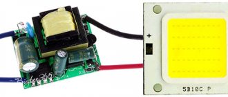
But this is a simplified model for connecting LEDs; most LED lamps already have a built-in driver (circuit) that converts 220V AC voltage into 5-24V DC voltage for their reliable operation. You can see the driver circuit in the following photo:
Some tips for creating a garland
When choosing the color of your future Christmas tree decoration, you should not pay attention to the RGB elements.
Assembly for a novice craftsman can become too complicated, and spending extra money to later connect them like ordinary components will be an unaffordable luxury. It is best to connect LEDs of different colors in parallel. Of course, you will have to make additional calculations of the resistor parameters, but the result will be much more interesting than when using single-color emitters. It is clear that a ready-made LED garland in a store is quite cheap. But you should understand that a product made by yourself will seem many times more beautiful. And the satisfaction that everything turned out as planned cannot be measured by any money.
When making such decorations, you should be extremely careful to ensure that there are no bare areas left and that the wires inside the controller do not overlap. The contacts must be properly soldered to avoid heating. It is necessary to understand that it will be located on the tree, and the needles flare up very quickly due to the resin it contains.
It makes sense to replace the power cable running from the controller to the socket - Chinese manufacturers are trying to save on everything. It is for this reason that the strands of this wire are slightly thicker than a hair. After opening the controller case, it makes sense to check the quality of soldering connections and contacts - in cheap models this is a sore spot.
Connecting LEDs to a 12V network
12 volts is a safe voltage that is used in particularly hazardous areas. These include bathrooms, baths, inspection pits, underground structures and other premises.
To connect to a DC voltage source rated 12V, similarly, to connect to 220V networks, a damping resistance is required. Otherwise, if you connect it directly to the source, the LED will instantly burn out due to the larger current flowing through.
The nominal value of this resistance and its power are calculated using the same formulas:
Unlike 220V circuits, to connect one LED to a 12V network we need a resistance with the following characteristics:
- R = 1.3 kOhm;
- P = 0.125W.
Another advantage of the 12V voltage is that in most cases it is already rectified (constant), which greatly simplifies the connection diagram. It is recommended to additionally install a voltage stabilizer such as KREN or an equivalent.
As we already know, a light-emitting diode can be connected to both 12V and 220V circuits, however, there are several variations of their connection to each other:
- Consistent.
- Parallel.
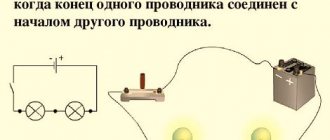
Serial connection
When connected in series through a current-limiting resistor, several LEDs are assembled into one chain, and the cathode of the previous one is soldered to the anode of the next one:
In the circuit, one current (20mA) will flow through all LEDs, and the voltage level will consist of the sum of the voltage drop across each. This means that using this connection diagram, you cannot include any number of LEDs in the circuit, because it is limited by voltage drop.
Voltage drop is the level of voltage that a light-emitting diode converts into light energy (glow).
For example, in the circuit the voltage drop across one LED will be 3 Volts. There are a total of 3 LEDs in the circuit. Power supply 12V. We consider 3 Volts * 3 led = 9 V - voltage drop.
After simple calculations, we see that we cannot include more than 4 LEDs (3 * 4 = 12V) in a parallel connection circuit, powering them from a regular car battery (or other source with a voltage of 12V).
If we want to connect more LEd in series, we will need a power supply with a higher rating.
This scheme was quite often found in Christmas tree garlands, however, due to one significant drawback, modern LED garlands use a mixed connection. We'll look at what the drawback is below.
Disadvantages of daisy chaining
- If at least one element fails, the entire circuit becomes inoperative;
- To power a large number of LEDs you need a high voltage source.
Use in everyday life
Where can you apply such a seemingly impractical scheme in everyday life?
The most widely known use of such structures is Christmas tree garlands.
You can also make consistent lighting in a long passage corridor and get loft-style lighting without much expense.
Are the light bulbs in your hallway or home constantly burning due to high voltage? The cheapest way out is to connect another one in series.
Instead of one 60W, you turn on two hundred parts and use them almost “forever”. Due to the reduced voltage of 110V, the likelihood of their failure is reduced hundreds of times.
Another original application, which I still do not recommend using, but some electricians resort to it in desperate situations. This is the so-called phasing of three-phase circuits.
Parallel connection
In this situation, everything happens the other way around. Each LED has the same voltage level, and the current is the sum of the currents passing through them.
Following from the above, we conclude that if we have a 12V source and 10 LEDs, the power supply must withstand a load of 0.2A (10 * 0.002).
Based on the above calculations, for a parallel connection you will need a current-limiting resistor with a nominal value of 2.4 Ohms (12 * 0.2).
This is a deep misconception!!! Why? You will find the answer below
The characteristics of each LED, even of the same series and batch, are always different. In other words: in order for one to light up, it is necessary to pass through it a current with a nominal value of 20 mA, and for the other this nominal value may already be 25 mA.
Thus, if only one resistance is installed in the circuit, the nominal value of which was calculated earlier, different currents will flow through the LEDs, which will cause overheating and failure of LEDs designed for a nominal value of 18 mA, and more powerful ones will shine at only 70% of the nominal value .
Based on the above, it is worth understanding that when connecting in parallel, it is necessary to install a separate resistance for each.
Disadvantages of parallel connection:
- A large number of elements;
- When one diode fails, the load on the others increases.
YOU CAN'T DO THIS!!!
As noted above, LEDs do not necessarily have the characteristics stated by the manufacturer. There is always variation. And so we set the current to 0.35 amperes and look at the glowing line of LEDs. But they all need different current. One, as we calculated, 25mA, another - 20mA, the third 21mA, but we found a completely crooked LED, it only needs 15mA. And we pass 25 through it - almost 2 times more. The LED gets hot and burns out quickly. There is 1 less LED in the line. Now we need 35mA to power the remaining LEDs. So far, things don't look particularly bad. We have limited the current with a margin. We're great. But another LED failed. There are 13 left. Now all our current is divided not into 15, but into 13 LEDs. Each of them accounts for 26mA. Now absolutely all LEDs operate at increased current. Very soon the next one will overheat. The most persistent ones will receive 29 mA - 116% of the nominal value. Just 2 burned out LEDs started a chain reaction. Soon the entire line will burn out, and you will never understand why (or you will understand, we just sorted everything out). Actually, it’s easy to get rid of such a sad scenario. Each LED needs to have its own current-limiting resistor. For a current of 25mA and a voltage of 12V, a 480 Ohm resistor is needed. This will not save you from the problem of “crooked” LEDs, but their burnout will not affect the others in any way.
Advantages: highest reliability. Disadvantages: high current consumption, high cost of the circuit.
Correct parallel connection of three LEDs
Parallel connection of LEDs is ideal. Always try to connect LEDs in parallel and limit the current of each LED individually with its own resistor. If you use LED drivers (current stabilizers), then each LED needs to connect its own driver. This is why parallel circuits with many LEDs become too expensive. In reality, you have to make a compromise and combine LEDs into chains.
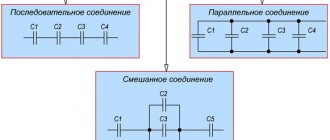
Mixed connection
This connection method is the most optimal. All LED strips are assembled using this principle. It involves a combination of parallel and serial connections. You can see how it is done in the photo:
The circuit involves connecting in parallel not individual LEDs, but serial chains of them. As a result of this, even if one or more chains fail, the LED garland or strip will still shine equally.
We looked at the main ways to connect simple LEDs. Now let's look at the methods for connecting high-power LEDs, and what problems you may encounter if connected incorrectly.
Instead of an epilogue
Every self-respecting home craftsman must know which connection is called serial and which is parallel and be able to perform it. These skills will be useful not only when making garlands. You can encounter different types of connections anywhere. For example, in a home electrical network, all sockets are connected in parallel, while the switches are switched in series. The main thing is to remember the basic rules, follow them and be attentive to detail. In this case, any work that a home craftsman undertakes will be completed safely, reliably and at the proper level.
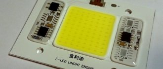
How to connect a powerful LED?
For powerful light-emitting diodes to work, just like simple ones, we need a power source. However, unlike the previous version, it should be an order of magnitude more powerful.
To illuminate a powerful 1W LED, the power source must withstand at least 350 mA of load. If the rating is 5W, then the DC power source must withstand a current load of at least 1.4A.
For the correct operation of a high-power LED, it is necessary to use an integrated voltage stabilizer of the LM type, which protects it from voltage surges.
If you need to connect not one, but several powerful LEDs, we recommend that you familiarize yourself with the rules for serial and parallel connection, which were described above.
Connection errors
- Direct connection to power source. In this case, the LED will burn out instantly, since there is no current limiting resistor.
- Parallel connection via one resistor.
LEDs will gradually fail because the operating current is different for each one. - Serial connection with different current consumption.
With this connection scheme, there are 2 options: either some will simply shine dimmer than others, or those designed for less current will burn out. - Incorrectly selected limiting resistor.
If the resistance is incorrectly selected, a large current will flow through the LEDs, as a result of which they will overheat and eventually burn out. With high resistance, they will not shine at full strength. - Connection to an alternating voltage network rated 220V without a diode or other protection components. If when connecting from a 220V network, e
If you do not install an additional diode, an amplitude voltage value of 315V will appear on the LED, which will instantly disable it.
220 volt LED driver circuit
The 220 volt LED driver circuit is nothing more than a switching power supply.
As a homemade LED driver from a 220V network, we will consider the simplest switching power supply without galvanic isolation. The main advantage of such schemes is simplicity and reliability.
But be careful when assembling, since this circuit has no current limit. The LEDs will draw their required one and a half amperes, but if you touch the bare wires with your hand, the current will reach ten amperes, and such a shock is very noticeable.
- The simplest driver circuit for 220V LEDs consists of three main stages:
- capacitive voltage divider;
- diode bridge;
- voltage stabilization cascade.
The first stage is capacitance on capacitor C1 with a resistor. The resistor is necessary for self-discharge of the capacitor and does not affect the operation of the circuit itself. Its rating is not particularly critical and can be from 100 kOhm to 1 Mohm with a power of 0.5-1 W. The capacitor is necessarily non-electrolytic at 400-500V (effective peak voltage of the network).
When a half-wave of voltage passes through a capacitor, it passes current until the plates are charged. The smaller its capacity, the faster the full charge occurs. With a capacity of 0.3-0.4 μF, the charging time is 1/10 of the half-wave period of the mains voltage.
In simple terms, only a tenth of the incoming voltage will pass through the capacitor.
The second stage is a diode bridge. It converts alternating voltage to direct voltage. After cutting off most of the half-wave voltage with a capacitor, we get about 20-24V DC at the output of the diode bridge.
The third stage is a smoothing stabilizing filter. A capacitor with a diode bridge acts as a voltage divider. When the voltage in the network changes, the amplitude at the output of the diode bridge will also change.
To smooth out the voltage ripple, we connect an electrolytic capacitor in parallel to the circuit. Its capacity depends on the power of our load. In the driver circuit, the supply voltage for the LEDs should not exceed 12V. The common element L7812 can be used as a stabilizer.
The assembled circuit of a 220-volt LED lamp begins to work immediately, but before connecting it to the network, carefully insulate all exposed wires and soldering points of circuit elements.
Driver option without current stabilizer
There are a huge number of driver circuits on the network for LEDs from a 220V network that do not have current stabilizers.
The problem with any transformerless driver is the ripple of the output voltage, and therefore the brightness of the LEDs. A capacitor installed after the diode bridge partially copes with this problem, but does not completely solve it.
There will be ripple on the diodes with an amplitude of 2-3V. When we install a 12V stabilizer in the circuit, even taking into account ripple, the amplitude of the incoming voltage will be higher than the cutoff range.
Voltage diagram in a circuit without a stabilizer
Diagram in a circuit with a stabilizer
Therefore, a driver for diode lamps, even one assembled with one’s own hands, will not be inferior in pulsation level to similar units of expensive factory-made lamps.
As you can see, assembling the driver with your own hands is not particularly difficult. By changing the parameters of the circuit elements, we can vary the output signal values within wide limits.
If you want to build a 220-volt LED floodlight circuit based on such a circuit, it is better to convert the output stage to 24V with an appropriate stabilizer, since the output current of the L7812 is 1.2A, this limits the load power to 10W.
For more powerful lighting sources, it is necessary to either increase the number of output stages, or use a more powerful stabilizer with an output current of up to 5A and install it on a radiator.
Video
Connection errors can lead to unpleasant consequences, from simple breakdown of LEDs to self-harm. Therefore, we strongly recommend watching a video where common errors are discussed.
Conclusion
After reading the article, we can conclude that all LEDs, regardless of the operating voltage, are always connected in parallel or in series - a school physics course. It is also worth remembering that no LED is connected directly to a 220V network; you should always use protective elements in the connection diagram. The type of protective elements used depends on the type of light-emitting diode being connected.
Is it necessary to change fluorescent light bulbs to LED lamps?
Today we can confidently say that LED light bulbs of any form factor are superior to their fluorescent counterparts in almost all respects. Moreover, LED technologies continue to progress, which means that products based on them will be even more advanced in the future. To confirm the above, a comparative description of two types of tubular lamps is given below.
T8 fluorescent lamps:
- MTBF is about 2000 hours and depends on the number of starts, but not more than 2000 cycles;
- light spreads in all directions, which is why they need a reflector;
- gradual increase in brightness at the moment of switching on;
- the ballast (ballast) serves as a source of network interference;
- degradation of the protective layer with a decrease in luminous flux by 30%;
- The glass flask and the mercury vapor inside it require careful handling and disposal.
T8 LED lamps:
service life is at least 10 thousand hours and does not depend on the on/off frequency; have a directional luminous flux; instantly turns on at full brightness; the driver does not affect the power grid; loss of brightness does not exceed 10% over 10 thousand hours; have significantly lower power consumption; completely environmentally friendly.
In addition, T8 LED lamps have twice the light output with equal energy consumption, are less likely to fail and have a manufacturer’s warranty. The ability to place different numbers of LEDs inside the bulb allows you to achieve an optimal level of illumination. This means that instead of a T8-G13-600 mm 18 W fluorescent lamp, you can install a 9, 18 or 24 W LED lamp of the same length.
Having weighed all the pros and cons, we can conclude that converting a fluorescent lamp to an LED light bulb is completely justified, both from a technical and economic point of view.