Home > Theory > Transformer no-load experience
Transformer performance can be predicted by knowing the equivalent circuit parameters. These values are established in experiments of no-load and short-circuit of the transformer, which are carried out without an actual load. Moreover, the tests give a more accurate result, in contrast to testing a loaded device.
Transformers
In accordance with the obtained figures, transformer efficiency can be easily determined in the future at any power indicator and any load current.
Idle experience
With the help of testing it is possible to establish:
- transformation ratio;
- how do current, power, and no-load power coefficient cosφ depend on the applied voltage;
- power losses in a steel magnetic circuit.
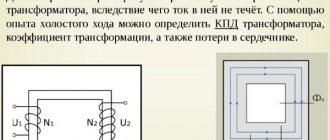
From the very name of the experiment it follows that it is carried out when the terminals of the secondary winding remain open, and the input power is supplied from the high voltage side. A reverse circuit is also used with power supply from the LV side and opening of the primary winding terminals.
The transformer no-load test is performed by connecting the selected winding to an alternating current power source through various instruments: ammeter, voltmeter, wattmeter. In order to establish the transformation ratio, a voltmeter is also connected on the other side. The applied voltage can be varied during the test. As a rule, its regulation occurs in the range of 0.6-1.1 from the nominal value.
Scheme for test x.x.
In an unloaded device, the primary current is very low - 3-5% of In. Losses in the wires of the transformer winding are insignificant.
Important! Transformer in idle mode. operates at Un, the generated magnetic flux in the steel magnetic core corresponds to the highest values. Almost all energy consumption is used to heat the core.
Measurements to calculate the transformation ratio
- After supplying the supply voltage, readings from two voltmeters are recorded synchronously. The transformation ratio is then calculated according to the formula:
K = U1/U2.
For three-phase devices, readings of phase or line voltages are taken;
- When connecting the windings of three-phase devices ∆/Y and Y/∆, the phase coefficient is measured by applying voltage to one phase and short-circuiting the others in turn. On the delta side, one phase is short-circuited and the remaining phases are energized. The calculated phase coefficient must be multiplied by 2 if the voltage is applied to Y, and divided by 2 if it is ∆.
Important! The phase coefficient value is calculated when significant deviations of the linear indicator are observed.
Definition of losses
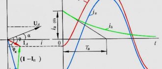
Graphic characteristics of no-load (no-load) are constructed based on several values of current, voltage and power read from devices in the process of voltage regulation. Quantitative current values for devices with low power indicators do not exceed 10% of the nominal values, and for high-power devices - 2%.
Formula for calculating the no-load power factor:
cosφ = P/I x U.
Important! In x.x mode. cosφ is 0.2-0.3.
The power indicator measured by a wattmeter is the power loss in the steel core.
You can also define:
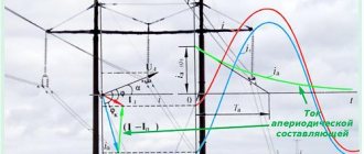
- magnetizing component of the current x.x.:
Im = I x sinφ
- active part of the current x.x.:
Ia = I x cosφ
- reactance:
X = U/Im
- resistance representing active losses in the magnetic circuit:
R = U/Ia.
General design and operating principle of the transformer
Structurally, the transformer consists of the following main parts:
- Closed core made of ferromagnetic material.
- Windings
The windings can be wound on a rigid frame or have a frameless design. Specially treated steel is used as the cores of industrial frequency voltage transformers. In some cases, there are devices without a core, but they are used only in the field of high-frequency circuitry and will not be considered within the framework of this topic.
The operating principle of the design in question is as follows:
- When the primary winding is connected to an alternating voltage source, it generates an alternating electromagnetic field.
- Under the influence of this field, a magnetic field is formed in the core.
- The magnetic field of the core, due to electromagnetic induction, creates an induced emf in all windings.
The induced emf is created, among other things, in the primary winding. Its direction is opposite to the connected voltage, so they cancel each other and the current through the winding when there is no load is zero. Accordingly, the power consumption when there is no load is zero.
Short circuit experience
Transformer calculation
Testing consists of connecting the HV winding to the power source via a voltmeter, ammeter, or wattmeter. The terminals of the LV winding are short-circuited. The second name of the experiment is low-voltage testing. With a short-circuited secondary winding and Un, the current consumption is high, given the low winding resistance. This may cause significant heat build-up and damage to the machine.
Important! To limit the current, the HV winding must be at a low U, sufficient to create In in it. This value of U is called Us (short circuit voltage). Ukz is within five percent of Un.
Short circuit test
At In, voltmeter and wattmeter data are recorded.
In this experiment the following are calculated:
- active, reactive, total resistance of winding wires;
- copper losses.
Important! The magnetization of the core is affected by voltage, therefore, the power losses in it can be ignored due to its small value, and the wattmeter will display the copper loss indicator.
Power losses, which are read from the wattmeter, are determined by the formula:
P = I² x R.
Based on the readings taken, calculations are made:
- active resistance of winding wires – R = P/I²;
- total resistance – Z = U/I;
- reactance – X = √ (Z² – R²)*
- short-circuit power coefficient – cosφ = P/ U x I;
- U*sq = (Z x I/U) x 100%. This indicator in percentage terms is indicated in the technical data sheet of the device.
, Ohm
3.
Contents and order of work
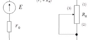
To study the electrical circuit according to the diagram in Fig. 1P measurement protocol uses: DC voltage sources from the POWER MODULE
: voltage source
E
1 = 9 V (
UZ 1
), current source
J
2
=
50 mA (
UZ 2
);
measuring instruments from
DC MEASURING
MODULE Passive elements and the electrical circuit are selected from the RESISTOR
MODULE ; for the resistor
Rn
the RESISTANCE STORE is used .
· Assemble the electrical circuit according to the diagram shown in Fig. 1P. Check the assembled electrical circuit in the presence of a teacher.
Turn on the QF
POWER MODULE
block .
Turn on toggle switch SA 1
of sources
UZ 1
and
UZ 2
.
Set the value of resistor R
n =
R
1. If the arrows of ammeters
PA 1, PA 2
and
PA 3
the MEASURING MODULE
block deviate to the right, then the current value is considered positive and equal to the device reading. If the arrow of the device deviates to the left, the polarity of the device connection should be reversed, and the current value should be considered negative. The voltages on the elements are measured similarly with a PV voltmeter.
· Enter the values of measured currents and voltages into the table. 1P of the measurement protocol.
Determination of equivalent generator parameters
In short circuit mode ( R
n
=
0) measure the current
I
short-circuit and the currents of the branches.
· In idle mode (branch with R
n open) measure voltage
U
xx, no-load current. Enter the measurement data into the table. 1P.
Comparison of experimental and theoretical data
· Fill out the table. 2P.
Determination of experimental dependencies
Measure currents I
n,
I
1, voltage
U
n for those indicated in the table.
3P resistance values R
n. Enter the measurement data into the table. 3P protocol.
P from measurements
n.
· Turn off the QF
POWER MODULE
block .
· Construct experimental dependencies I
n(
Rn
),
Un
(
In
),
Pn
(
In
),
I
1(
I
3).
Measurement protocol for laboratory work No. 3
“Equivalent generator method. Linear relationships"
The diagram of the electrical circuit under study is shown in Fig. 1P. Indicate on the diagram under study the positive directions of currents in the branches and the polarity of connecting the devices. In subsequent experiments, the selected directions are taken as positive; the experimental value of the current in the branches is taken in accordance with the deflection of the instrument needle.
E
1 = ___ V,
J
2 = ___ mA, = ____ Ohm, = ____ Ohm, Ohm.
R
n = ____ Ohm
, mA
, mA
, mA
, mA
Transformer efficiency calculation
A transformer has two types of main losses: in the steel core and in copper. They are released as heat. Due to wasted energy, the output power of the device is not equal to the power consumption.
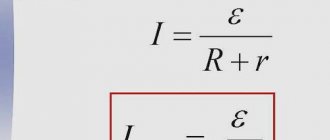
Transformer efficiency, or efficiency, is calculated by the formula:
η = output power in kW/power input in kW =
output power/(output power + core loss + copper loss),
or η = Pout/(Pout + Рхх + Ркз), where Рхх and Ркз are determined from experiments х.х. and short circuit
Short-circuit voltage – an important indicator in the technical characteristics of the transformer. It is used to determine whether the devices can be switched on for parallel operation, and to calculate the secondary U at different loads.
What does the magnetic flux of mutual induction in XX mode depend on?
The magnetic flux of mutual induction in a transformer depends on the method of placing the windings on the core and their design.
An important role is played by the fill factor of the magnetic circuit window, which shows the ratio of the total space to the space occupied by the winding.
The closer this coefficient is to unity, the higher the mutual inductance of the windings will be and the lower the losses in the transformer.
Loss table
Features of operation and application of the Tesla resonant transformer
When the second coil circuit is open, it does not use any operating power. The power that the first one consumes has a certain active percentage (this represents the losses of the device), but the reactive one, responsible for magnetization and given to the generator, dominates. As for the lost power, most of it is spent on magnetization reversal processes and the generation of magnetic circuit current eddies. Because of this, the latter begins to overheat. Since the leakage flux does not depend on the load electric current, there are power losses not only at idle, but also when applying loads. Another part of the losses (very small) is spent on heating the coil wire. Its low value is due to the wiring resistance and no-load current.
At a voltage of 10/0.4 kV, the amount of losses will increase as the power increases. For a rated power of 250 kVA, the losses will be 730 W, for 400 kVA - 1000 W, for 2500 kVA - 4200 W. After years of operation, processes occur in the magnetic circuit that increase the amount of losses: the insulation wears out, the structural characteristics of the metal change. Because of this, up to 50% of power can be lost.
Transformation ratio
When determining the operation of an installation, a concept such as transformation ratio is used. Its formula is presented below:
It follows that the voltage on the secondary circuit will be determined by the ratio of the number of turns. To be able to regulate the output electricity, a special device is built into the design of the installation. It switches the number of turns on the primary circuit. This is an antsapf.
To conduct the experiment at idle, the regulator is placed in the middle position. In this case, the coefficient is measured.
Single-phase devices
To carry out the presented experiment, when using a step-down or step-up household unit, the presented coefficient is taken into account. In this case, two voltmeters are used. The first device is connected to the primary winding. Accordingly, the second voltmeter is connected to the secondary circuit.
The input impedance of the measuring instruments must correspond to the nominal characteristics of the installation. It can operate in buck or boost mode. Therefore, if it is necessary to carry out repair work, not only the supply of low but also high voltage is measured on it.
Three-phase devices
For three-phase units, during the experiment, indicators on all circuits are examined. In this case, you will need to use 6 voltmeters at once. You can use one device that will be connected in turn to all measurement points.
If the value set by the manufacturer on the primary winding exceeds 6 kV, a current of 380 V is supplied to it. When measuring in high-voltage mode, it is impossible to determine indicators with the required accuracy class. Therefore, measurements are carried out in low voltage mode. It is safe.
Applying the coefficient
During the measurement process, the trunnion is moved to all positions specified by the manufacturer. In this case, the transformation coefficient is measured. This allows you to determine the presence of a short circuit in the turns.
If the phase readings have a scatter during measurements of more than 2%, as well as their decrease in comparison with previous data, this indicates deviations in the operation of the unit. In the first case, a short circuit is detected in the system, and in the second, a violation of the insulation of the windings is detected. The unit may not operate correctly.
Such facts require confirmation. For example, this could be a resistance measurement. An increase in the spread of the coefficient indicators can be influenced by an increase in the resistance between the contacts of the axle. When switching frequently, this situation occurs.