If you paid attention to this article, then you probably recently asked yourself the question: “What is an RCD and what is its purpose?” We will try to answer this question in as much detail as possible. Well, first of all, let’s say that the abbreviation RCD stands for residual current device.
What is an RCD
Technically, a disconnect device is a mechanical unit, the purpose of which is to automatically interrupt an electrical circuit when a specified imbalance current appears in it. Such devices have been used by professionals for a long time and are available in a variety of models: electricians are well acquainted with their types, their design, and their operating principles. But when installing home circuits, homeowners and the craftsmen they hire often do not fully understand why an RCD is needed and neglect to install it in the circuit, depriving the network of powerful protection.
It is especially important to install an RCD in the power supply circuits of wet rooms - in the bathroom, sauna, bathhouse, etc. Sockets and electrical consumers installed there are at increased risk, so protecting the bathroom network is strictly necessary.
The mechanism protects against:
- fires due to power problems;
- damaging a person with electricity from a damaged circuit.
One of the key tasks of electrical engineering is to protect people from electric shocks. Its solution required considerable time and technical research. After all, even if conventional circuit breakers perfectly control the load current, they will not save a person from danger if they touch a conductive part or cable under high voltage. Also, these devices are not able to respond in a timely manner to leakage currents associated with violations of the integrity of the insulation of cable systems and effectively protect against fires arising for this reason.
The situation improved after the development of the RCD. They monitor the differential current and disconnect the circuit after it reaches a certain set value. These devices received the name UZO-D (differential). During the Soviet Union, UZO-D was produced by the country's own industry, at the Gomel Electrical Apparatus Plant. Nowadays, there are both imported and Russian-made samples on the market.
There are also differential circuit breakers that combine an RCD and a conventional circuit breaker. They are very popular for installation at home.
Purpose
The RCD compares the values of the input and output currents of the serviced circuit. When a difference is detected, indicating that the flow of electrons is escaping into foreign objects, the device opens the contacts.
Current leakage occurs in one of the following cases:
- the user received an electric shock;
- a phase short circuit occurred to the grounded body of the device: an accident that also threatens the user with electrical injury;
- contact has occurred between live parts and grounded metal objects, for example, a building structure, which is fraught with fire.
Therefore, if there is an unauthorized loss of current, it is extremely important to quickly de-energize the circuit.
It must be understood that the RCD does not protect the circuit from overloads and short circuit currents. This function is performed by automatic switches. There are two-in-one devices that include an RCD and a circuit breaker. In everyday life they are called difavtomats.
How it works
The principle of operation of an RCD in a single-phase network is simple. The device detects leakage electric currents going to ground and turns off the circuit. Detection is performed based on the difference in types of currents:
- energy leaving the RCD;
- electricity returning to the system.
In a working electrical network, these currents are equal in strength, but the direction should be opposite. If for some reason a leak occurs (broken insulation, touching a wire, and other situations), part of the electricity will go through a new “channel” to the “ground”. The electric current going to the residual current device will become less than the outgoing one. A similar thing will happen after some part comes under electrical voltage - for example, a housing or other conductive parts.
The difference in current readings is recorded by a transformer assembly with a ring core. The primary winding (neutral and phase) is located inside. The secondary winding is connected directly to the actuator that opens the electrical circuit. The circuit will operate without the presence of a person as a source of failure, detect a leak and remove power from the damaged line.
The operating principle of a two-phase RCD-D is described above. There are also three-phase protective devices: they detect leaks and unbalanced load distribution. These are more advanced devices that provide an additional level of protection.
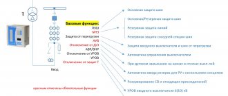
Main technical characteristics
Each RCD has a certain set of technical parameters that should be studied before purchasing:
- manufacturer;
- model name;
- operating current - the maximum current value that the device can switch;
- power supply parameters (voltage and frequency);
- leakage current - the maximum value of leakage current to which the device responds;
- RCD type;
- operating temperature range;
- rated conditional short circuit current;
- RCD device diagram.
Example of RCD operation
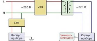
Let's give a small example of a typical RCD-D. Given:
- two-wire power supply circuit for 220 V, without grounding;
- as an energy consumer - a washing machine;
- switching device built into the circuit.
Normally, the RCD passes electricity directly and without obstacles. Incoming and outgoing currents are of equal importance. If, for example, an electric motor malfunctions, voltage will be applied to the body of the machine. By touching it, an unsuspecting person will be subjected to a powerful shock of electricity.
A leakage current and imbalance occurs: part of the energy flows through the body of the person under attack. Less electricity is returned to the RCD than was left, and the device breaks the circuit.
There are both simple mechanical protection devices and models with semiconductor contact breakers. There are also versions with more complex built-in logic. But electronic ones are more expensive and require additional power to maintain the operation of the circuits.
Device
The RCD device requires the presence of:
- leak sensor;
- polarized magnetic relay.
The operation of the device is based on laws based on incoming and outgoing electricity in closed circuits with extremely high loads. This indicates that the current should have only one value, regardless of the phase of passage.
There are three magnetic coils inside the device. A phase passes through the first, and zero through the second. The current creates magnetic fields at the input and output of the device coils.
If everything works as it should, the mutual fields cancel each other out. If an imbalance occurs on one of the coils, that is, a current leak occurs, this will lead to the action of the third coil, which has a relay to turn off the power.
RCD classification
Let's look at what types of protective devices there are in accordance with GOST standards.
According to their mode of action they are divided into:
- RCD with auxiliary power supply;
- without additional source;
- with automatic switching on after restoration of power supply from the source;
- without automatic switching on;
- with shutdown after detection of a dangerous source failure situation;
- without such automatic shutdown.
By installation type:
- stationary RCDs mounted on standard permanent electrical wiring;
- portable - mounted on flexible cables and extension cords.
By number of poles:
- single-pole two-wire RCDs;
- devices with two poles;
- three-wire two-pole models;
- three-pole protective systems;
- four-wire three-pole models;
- four-pole RCDs.
There is a classification according to the type of protection against overcurrents at the poles and overloads:
- without and with overcurrent protection;
- without built-in overload protection system;
- with protection against short circuits (short circuits).
According to the possibilities of setting the DT shutdown value:
- adjustable - with discrete adjustment;
- unregulated RCDs.
In terms of resistance to impulse voltages:
- with the device turned off after the pulse current appears;
- resistant to surge voltage.
Another important characteristic is control of the DC component of the differential current (DC). There are several types of RCDs:
- AC. They are turned off when sinusoidal DTs occur or gradually increase;
- A. These models are disconnected from sinusoidal differential currents and pulsating direct currents. There are varieties with switching off from pulsating with a level of up to 0.006A and controlling the phase shift angle;
- B. Similar to A, they open the circuit with sinusoidal variables and constant DTs - including flow modulations up to 0.006 A. In addition, type B can switch off from constant DTs with a rectifier.
The considered types and classification characteristics determine the choice of RCD in a particular situation, the method and location of installation, and other important details of the design of the electrical network. In addition to the above, there are some general characteristics shown in the table:
| RCD characteristic name | Possible values according to the passport |
| Network voltage, V | 100–440 |
| Rated operating current, A | 6–200 |
| Nominal DT shutdown, A | 0.006–20 |
| Rated non-switching DT of the device, A | 0.5 |
| Limit non-switching DT with distorted phase symmetry, A | 6 |
The RCD must operate quickly. The time is set by GOSTs (in particular, GOST R 50807-95) and is calculated for various models operating with certain rated breaking currents. For example, for a device with a trip temperature of 0.03 A, the response time should be 0.5 seconds. If the threshold value is exceeded twice, the shutdown timeout is 0.2 seconds, and if it is exceeded eight times, the RCD-D will open the circuit in 0.04 s.
Connection to a three-phase network (with and without grounding)
Connecting an RCD in a three-phase network with grounding is not much different from a single-phase one. Protection of three-phase load circuits is carried out by a three-phase (four-pole RCD). In this case, single-phase load circuits must be protected with a separate single-phase (two-pole) RCD. There are many schemes on the Internet where a three-pole RCD is used simultaneously to protect both three-phase and single-phase consumers. This is only permissible if the RCD is fireproof, with a leakage current of 100 mA or more. Connecting an RCD in a three-phase network without grounding is prohibited by the PUE.
How does an RCD work?
There are two types of devices:
- electromechanical;
- electronic models of RCDs.
Electromechanical
These devices consist of several parts:
- zero sequence electric current transformer. It monitors leaks and transfers energy to the secondary winding of the transformer;
- magnetoelectric element performing threshold functions;
- a relay that is triggered when a magnetoelectric “latch” is triggered.
All mechanical parts must be very high-precision, which is why the cost is high. But it is compensated by reliability and the ability to work without additional power, detecting leaks at any voltage value. The independence factor is extremely important: a mechanical RCD will detect a leak and turn on the relay in 100 percent of cases. For electronic devices, this percentage is lower, since if the total voltage level is below a certain threshold, the circuit will be inoperable. Therefore, it is electromechanical models that are internationally recognized as the standard and mandatory for use, especially at critical facilities.
Electronic RCDs
Their cost is sometimes an order of magnitude lower than the classic ones. But there is also the above-mentioned drawback - not a 100% guarantee of operation. The design of such protection systems is similar to that of electromechanical ones. But instead of a sensitive element, a logical comparison unit is installed - a zener diode, a comparator. The functionality of the device is ensured by the filter and rectifier.
A signal amplifier is also required, since the included transformer is a step-down transformer. Unfortunately, the amplifier modulates not only the “useful” load, but also noise, which also reduces reliability. But to protect an ordinary residential premises, an electronic RCD in quite a number of cases is sufficient. The choice should be based on the details of the electrical installation project being implemented.
Let there be srach!
A separate discipline of debate is which RCD is better, electromechanical or electronic. An electromechanical RCD uses differential current energy to turn off, so it can operate if the neutral conductor breaks, and in general it does not contain delicate electronics, but contains delicate mechanics. An electronic RCD requires power to operate the electronic amplifier, so if the zero is broken, it stops working, often without disconnecting the circuit. Each configuration has its own advantages and disadvantages. And to protect against zero loss, I strongly recommend installing a voltage control relay.
But since most readers expect a specific answer from me, I will say that this is not important. There are standard requirements, there are required characteristics, and in the end there is a competitive price. Therefore, the manufacturer gives exactly what is required of him, but how the desired is obtained is not so important. And if the manufacturer is a handyman, then the absence of electronics does not automatically mean that the product will be suitable. In addition, no manufacturer has been able to produce a type B RCD without adding electronics.
To monitor the serviceability of the RCD, there is a “test” button on the front panel, which, by closing the circuit with a resistor, simulates the appearance of a differential current. If the RCD turns off when you press the test button, then it is working properly. Manufacturers recommend checking the serviceability of the RCD monthly (what optimists!), or, realistically, I’m talking about testing once every six months.
Checking the RCD operation
Checking the RCD for correct operation is usually performed using a special test button - it is located on the body of almost every device of this type.
There is also a way to test the RCD with a battery: connect a 10 cm wire to one of the poles, take a AA battery and connect the wires to its poles (the second RCD wire is usually present from the factory). When the battery wires touch the battery, the protection should work.
When you can't trust anyone
Manufacturers of some devices cannot rely that the buyer is adequate and there is protection in his electrical panel, so they add their own.
In the form of a personal RCD for a device in a plug or in the form of a box on a cord. If the buyer connects the boiler with plastic pipes and does not ground the housing, then if the heating element loses its tightness, electricity will flow through the water in the pipes through the person into the grounded bath. This RCD protects one device in particular, and in some countries there are regulations that require the addition of RCDs to certain types of devices. As you can see, the device also contains a “test” button to check the functionality of the protection.
Standards
As mentioned above, the requirements for RCDs are given in various GOSTs. The package of documentation related to RCD-D covers AC devices used in protection against electric shock and the negative consequences of leakage with voltages up to 440 V and power up to 200 A. Among these documents:
- GOST R 50807-95 - classifies, lists the characteristics of RCDs and contains testing measures and methods;
- GOST R 30331.3 - defines the rules of application.
The standards are similar to internationally accepted ones and contain all the necessary information. Note that GOST R 50807-95 classifies only mechanical electrical switching devices/complexes as RCD-D.
Purpose of the protection device
The RCD ground loop device is a PE conductor of neutral conductive housings or parts of electrical mechanisms with a resistance not exceeding 4 Ohms.
If a leakage current occurs, these equipment elements may be energized, which poses a danger to human and animal life in contact with them, as well as to property in general.
To save from electrical injuries is the calling of survey devices. When a leakage current is detected, they turn off the voltage.
The greatest danger lies in the fact that such disturbances in the circuit are invisible and, in rare cases, noticeable, when you can feel a slight electric shock when touching the device.
The main reason for this phenomenon is a violation of the insulating layer of the wiring. Uncontrolled processes can cause great harm, which is why protective equipment is becoming increasingly popular in domestic environments.
The impact of conductive networks on the human body can result in disastrous consequences. This problem was solved with the help of RCD control devices belonging to the protective segment. Basic requirements for installation and use are described in IEC 60364
The use of RCDs is most widespread in single-phase networks with alternating current and neutral line grounding, as well as with voltage levels up to 1 kW in the household power supply format.
RCD selection
When the fundamental issue of the availability of protection has been resolved, it is necessary to understand which RCD to install in a private house or city apartment. When selecting a model, you should focus on the power supplied to the housing, the number of consumers, their individual and total power, the type of cable at the input and on the internal wiring. For example, for a conditional object with a consumer power of 1850 W and internal wiring of 3 × 2.5 sq. mm, 8 meters long, based on calculations, we select and install a two-pole electromechanical RCD type A with a short-circuit current of 6000 A and a differential breaking current of 10 A. For example, a washing machine in an apartment is suitable for such characteristics.
When selecting a protection system, its parameters should be calculated. The calculation of RCD power is done using special formulas. To help those who do not know how to select an RCD and a machine based on power, there are various correspondence and compatibility tables.
In general, to calculate the target leakage current, you must be guided by the formula:
- IΔ= IΔep + IΔnetworks =0.4 Icalc+0.01Lwires, where:
- IΔep is the leakage current of the energy receiver, indicated in milliamps;
- IΔnetwork—mains leakage current, also in mA;
- Icalc—calculated load current in the electrical circuit under consideration (in amperes);
- Lwire is the total length of the phase conductor in meters.
IΔ in the example under consideration is equal to 3.45 mA.
The rated trip current must be at least three times higher than IΔ!
Thus, the final formula for how to choose an RCD based on power:
- IΔn > = 3 IΔ.
- 3 IΔ=3×3.45=10.35 mA
The above calculation of the denomination was carried out using exactly this method.
Video on the topic
About the types of RCDs and selection rules in the video:
So, for domestic conditions, in the vast majority of cases, electromechanical 2-pole RCDs with a leakage current setting of 30 mA or 10 mA (for wet rooms) class A with installation on a DIN rail are suitable.
A difavtomat - a device that combines the functions of an RCD and a circuit breaker - is more expensive than individual devices, but takes up less space in the panel. It is better to choose a difavtomatic device with an indicator that helps determine which part has tripped - the RCD or the automatic device.
Causes of electrical fires
Causes of electrical fires may include:
- Heating of conductors (local or over an extended area) due to overload.
- Sparking at the site of poor electrical contact (in connections, at the terminals of electrical appliances and devices)
- Leakage from non-insulated sections of the circuit (in connection, branch and feed-through boxes, distribution boards, electrical devices).
- The burning of an electric arc in any part of the circuit caused by a short circuit current.
- Damage to cable insulation.
Damage to cable insulation can occur for the following reasons:
- Electrical - from overvoltage and overcurrent.
- Mechanical - impact, pressure, squeezing, bending, damage by a foreign body.
- Environmental influences - humidity, heat, radiation (ultraviolet), aging, chemical exposure.
The development of a short circuit from a leakage current, leading to a fire, occurs as follows:
- At the point of microdamage to the insulation, an extremely small point current begins to flow between energized conductors.
- Under the influence of humidity, pollution, and the penetration of dust over time, a conductive bridge is formed through which leakage current flows.
- As the insulation condition deteriorates, starting from a current value of approximately 1 mA, the conductive channel gradually becomes charred, a “carbon bridge” appears, and the current continuously increases.
- With a leakage current of 150 mA, which corresponds to a power of 33 W, there is a real danger of fire due to the heating of various flammable materials by the heat generated at the site of insulation damage.