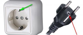
Instructions for replacing an electrical plug will be useful for newbie electricians who do not know which conductor to connect to which pin. Today, all household appliances are connected to the network using a Euro plug, which differs from the usual version by the presence of grounding. As a result, instead of the usual 2 wires, you need to connect 3, which causes difficulties for some home craftsmen. Next, we will tell you how to change the plug on the wire, providing step-by-step instructions with photo examples, as well as visual video lessons!
What to check lastly when replacing a plug
- Make sure the wires are connected to the correct terminals.
- Make sure there are no erroneous wires.
- Make sure the flexible clamp secures the outer sheath and not the thinner wires. If you don't do this, the wires may become loose.
- Make sure all screws are tight.
Protection connection.
Connect the correct fuse for the device. Read the manual if you are not sure which amplifier fuse is appropriate.
Reinstalling the cover and securing it.
At the very end, we assemble the fork body, installing the cover with a screw.
This is how a plug with three wires is connected. And there are quite a lot of situations when you need to connect a plug. For example, when you bought an oven without a plug, and you have to connect it yourself. Or other situations during electrical installation work in an apartment or house.
This concerns Euro forks. What to do with old forks?
DIY tutorial: how to make an extension cord. Easier than it seems!
For most people, a country house is not only a vacation spot. Fixing a roof, putting up a fence, washing a car, mowing the grass on the property is a lot of work! And after work it would be nice to take a shower, have lunch, and watch a movie. It sounds good. But in reality, the power cords of equipment and tools are not enough to reach a fixed outlet. And besides, those few power sources are already occupied by basic household appliances.
An extension cord will help you! However, ready-made carriers are expensive and are not always ideal in length and power. You can make an extension cord yourself - there is nothing complicated about it. And most importantly, you will be confident in the quality of the chosen materials and the integrity of the assembly. We will tell you how to calculate the load and wire cross-section. In the steps we will describe the assembly process in detail. And you will find all the necessary parts and accessories on our website.
Installation of sockets
Before looking for how to wire a 4-socket outlet, it is better to become familiar with the requirements and installation process of a simple single device. The fact is that there is no difference in installing double, triple sockets, or devices with a large number of sockets.
Complete blackout is the first condition for any electrical work. When installing, be sure to pay attention to the color coding of the wires. Phase wires (L) can be:
- white;
- turquoise;
- brown;
- red;
- orange;
- pink;
- gray;
- purple;
- black.
But still, 3 colors are more often used - white, black or brown. Neutral (N) - zero working contact - blue or blue. Grounding (PE), which is often called “zero protection,” has a shell of yellow and green stripes (longitudinal, transverse), sometimes a yellow-green tint, and can also be purely yellow or only green.
The process of installing sockets looks like this:
- First, a hole of the required diameter is drilled in the wall for the socket box, and grooves are made for electrical wiring. These operations are not necessary if the task is simple - replacing a failed socket. In this case, pull the end of the power cable out and remove all accumulated debris using a vacuum cleaner or brush.
- To install the socket box, prepare a cement/gypsum mortar. After applying it, insert the installation box into the hole, pull the cable into it, and fix it flush with the wall. Leave the work until the solution has completely set.
- Then the insulation is removed from the ends of the wires, they are inserted into the contact mounts (phase - on the left, zero - on the right, protective cable - in the center) and tightened with a screwdriver. Check the connection for strength.
- The body is installed inside the box, aligned horizontally, and temporarily fixed on both sides with self-tapping screws. The position is corrected using a level, then the fasteners and spacer tabs are tightened, finally fixing the socket body
- Attach the cover to the body and tighten the central screw. Turn on the electricity and use the indicator to check the functionality of the outlet.
Parallel connection
Popularly, the connection diagram by powering several sockets to one power cable is called a “star”. An electrician installs a distribution box and connects branches to it in accordance with a pre-developed electrical wiring plan. The advantage of this method is that each power point operates autonomously. Voltage disappears at all electrical points only if the main electrical cable burns out. In this case, the load on each point can be selected based on the power of the electrical appliance. The only negative is the high wiring consumption.
Fork adaptation
Quite often there are electrical appliances whose plugs are not suitable for domestic sockets. In this case, there is only one solution to the problem - connecting the device through a special adapter - an adapter.
Adaptation of three-pole design type IEC 60906-1
The distance between the pins for this configuration is 19 mm, the diameter of each pin is 4 mm, like the C5 type. But unlike the latter, they are equipped with an additional grounding pin, which will not allow you to insert the plug into the socket.
To solve the problem, the structure is clamped in a vice and carefully, so as not to damage the necessary pins, the third one is cut off with a hacksaw. The absence of a grounding pin allows you to easily connect the device to an outlet
Adaptation of the English model BS 13-63
Such Euro plugs also have three pins, but are flat in shape. Two of them are on the same horizontal line, they are designed to supply power voltage, and the third is for proper connection and grounding.
The width of each pin is 6.5 mm. The interval between the internal planes is 16 mm, as with type C5. To make the mechanism usable, you will need to reduce the width of the pins by 2.5 mm and remove the ground. The excess is removed with a hacksaw, and with its help the remaining pins are ground off. This is where the adaptation ends, the plug can be used at home.
Read further:
How to assemble a grounding plug
How to replace a plug on a wire
How to change a plug on a wire
How to assemble a socket plug
How to fix a socket plug
Is it possible to take it apart?
Before you repair a socket plug, you need to understand whether it can be disassembled or not.
There are several types of collapsible forks. Unfortunately, there is no single global standard for such devices, and this causes a lot of problems. For example, you bought a device abroad, you are trying to turn it on, but the pins do not fit in because the distance between them is greater or less than that at which the holes are located at the socket. Or there is an additional rod of an incomprehensible shape, which there is nowhere to stick.
You can use an adapter, but most often in such cases the plug is removed:
- unscrews;
- trimmed.
To repair an electrical plug in this situation, replace the old one with a new one that is suitable specifically for your outlet. Such an operation usually has no effect on the operation of the device.
Types of electrical plugs
Currently, in Russia, all electrical appliances are produced with cords at the end with two types of permanent plugs, type C, in accordance with GOST 7396.1-89. The body of each plug is usually marked with a marking indicating its technical characteristics - the maximum permissible current and the permissible supply voltage. This does not mean that the given one is of such strength, but only indicates that the plug is designed to transmit current up to the specified value.
C5
(analogue of European electrical plugs CEE 7/16) - with round pins with a diameter of 4 mm, converging slightly towards the free ends, the pins are insulated to a length of 10 mm from the body, without a grounding contact. The C5 plug is designed for a load current of up to 6 A (with a supply voltage of 220 V it can withstand a power of 1300 W).
C6
(analogous to European plugs CEE 7/17) - with round pins with a diameter of 4.8 mm, there are three-pole with a grounding contact and two-pole without a grounding contact. The C6 plug is designed for a load current of up to 10 A (with a supply voltage of 220 V it can withstand a power of 2200 W).
There are still many devices in use with cords equipped with collapsible plugs type C1-b
with round pins with a diameter of 4 mm without a grounding contact and designed for a load current of up to 6 A (with a supply voltage of 220 V it can withstand a power of 1300 W).
We carry out calculations
To correctly select components for an extension cord, you need to know two parameters - voltage and current. The voltage is usually 220 V in household networks, 380 V in industrial networks. The current is calculated using a formula based on the connected load, that is, the total power of consumers. In our calculations we neglect inrush currents.
For example, we plan to connect a water pump (800 W), a drill (400 W) and a trimmer (1000 W) to the extension cord. The total power is 2200 W.
To determine the current, divide the resulting amount by the voltage.
2200 (W) : 220 (V) = 10 (A)
Now we can select the socket and plug. Current values are always indicated in the technical specifications, as well as on the housings of the elements.
To determine the required cross-sectional area of the wire, refer to the table below. It is better to choose a wire with the closest value upward, so that there is a reserve when connecting more powerful consumers.
Table for determining cable cross-section
| Current, A | power, kWt | Cable cross-section, mm2 | |
| 220 V | 380 V | ||
| 11 | 2,4 | — | 0,5 |
| 15 | 3,3 | — | 0,75 |
| 17 | 3,7 | 6,4 | 1,0 |
| 23 | 5,0 | 8,7 | 1,5 |
| 26 | 5,7 | 9,8 | 2,0 |
| 30 | 6,6 | 11 | 2,5 |
| 41 | 9,0 | 15 | 4,0 |
| 50 | 11 | 19 | 6,0 |
| 80 | 17 | 30 | 10 |
Difference between zero and ground
Some novice electricians do not know what color the ground wire is or what it is needed for. Let's look at this question in more detail. Electric current flows through zero and phase, so you cannot touch them. The ground serves to remove voltage if it breaks through to the body of the device. This is a kind of protection that has become mandatory in recent years - some devices do not work if they are not grounded.
If you are not sure which wire is ground and which is zero, then use the following tips. They will help you decide without the color code of the wires
- Measure the resistance of the wire - it will be less than 4 ohms (check that there is no voltage on it so as not to burn the multimeter).
- Find the phase, use a voltmeter to measure the voltage between the supposed zero and ground. On the ground the value will be higher than at zero.
- If you measure the voltage between the ground and a grounded device (for example, a battery in a multi-story building) with a multimeter, the voltmeter will not detect the voltage. If you measure the voltage between zero and ground, a certain value will be displayed.
All this is true only for three or more conductor cables. If there are only two wires in the cable, then by default one will be ground (blue), the second phase (black or brown).
Observe cable connections
Answers from experts
Ivan:
Uh comrade, you've stumbled upon a three-phase thing!
380 volts. 3 phases and zero.
It may be possible to connect, but you need to have it checked by a specialist. If you are not familiar with this, you should not do it. Minimum, it will blow out the fuses, maximum, it will burn the house down))
Alexey Bebekin:
A regular fork typically has four tines. So what's the problem? Each tooth has a wire. It's business.
DT830B:
There should be instructions, or contact the store for advice..
Pavel Ihalainen:
black to ground the rest - three phases
I don't give af**k:
definitely by twisting the wires in pairs. but it would be better to do this under the supervision of the one who is dragging, where in the unit these wires go) but I don’t know about the three-phase gimmick)
Andrey Silkov:
I don’t understand what kind of veins there are? if there are two zeros and two phases, twist zeros with zeros, phase with phase, and make a fork, if the market goes for a current of more than 220, then there are not enough cores... Is it the Chinese who are making this?
Yura:
3 to one, 1 to one. And on the nose.
Egor:
It really looks like you got it on 380 V. You can’t turn this on at home (without dancing with a tambourine)
Alexander Grigoriev:
!!!BLUE-zero !!!!YELLOW-GREEN-earth the rest of any color, even black or gray-brown-buckled PHASE or PHASES
I would ask again here with the COLOR of the conductors!!! !
and the model of the heater, even if you look at the instructions and study them, you’ll burn them!!!
Sergey:
Ring the ends and you will determine!
Andrey Gurich:
yellow is usually used for grounding. The other two are connected to the plug.
Pin:
Are you laughing or what? ? the third wire is to ground, don’t connect anything yourself, call a technician. the machine will burn out and all the wiring will fly away, and everything that is included in the network too
I&R:
yellow grounding. on the fork there is a place for it; the rest, no matter, put it on the two remaining terminals
Grandfather Au:
throw away the plug you need a 3 wire euro plug yellow ground the machine has a connection diagram blue this is PHASE
a lion:
Yellow - earth, the rest to the plug in any form
Truculentus:
GROUNDING (EARTH) The “ground” wire should be yellow-green in color. In the distribution panel (DP) it should be connected to the grounding bus, to the housing and the metal door of the panel. As for the distribution box, the connection goes to the grounding wires from the lamps and from the grounding contacts of the sockets. The “ground” wire does not need to be connected to an RCD (residual current device), therefore RCDs are installed in houses and apartments, since electrical wiring is usually carried out with only two wires
ZERO (NEUTRAL) The “zero” wire should be blue. In the distribution board it must be connected to the zero bus, which is designated by the Latin letter N. All blue wires must be connected to it. The bus is connected to the input via a meter or directly, without additional installation of the machine. In the distribution box, all wires (except for the wire from the switch) of blue color (neutral) are connected and do not participate in switching. To the sockets, the blue “zero” wires are connected to the contact, which is designated by the letter N, which is marked on the back of the sockets.
PHASE The designation of the phase wire is not so clear. It can be either brown, or black, or red, or white. In an apartment switchboard, the phase wire coming from the load consumer is connected to the lower contact of the circuit breaker or to the RCD. In switches, the phase wire is switched; during switching off, the contact closes and voltage is supplied to consumers. In phase sockets, the black wire must be connected to the contact marked with the letter L.
Yellow is redundant. Brown and blue can be connected to the plug in any way you like.
Anat.:
cut off 10cm of this wire and take it with the plug to your uncle's electrician, ask him to connect it, he'll do it - come home and connect it to the rest, insulate the wires
Victor Demin:
What if there are two yellow ones?
Features of replacing different types of electrical plugs
Replacement of European design
Stages of replacing a European-style electrical plug
As a rule, the need for replacement arises when the integrity of one of the pins has been damaged. The technology is quite simple:
- Replacement begins with dismantling the old Euro plug and removing the outer sheath from the wire. At least 5 cm is removed from the end.
- Each wire core is stripped approximately 15 mm. This length will be sufficient to connect wires in a European-style design.
- All bare wires are cut so that the length of the bare wires is no more than 10 mm. This is enough to replace the plug with a new one yourself.
- To ensure reliable contact, you need to bend the ends of the wires using pliers.
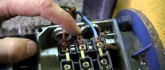
- The next step is the correct connection of the wires. Most cords have three wires. Brown – phase, yellow or green – ground, blue – zero.
- To prevent the plug from wobbling, it must be firmly fixed by clamping the wire with a plastic jumper.
- The final stage is to assemble the working mechanism and check its functionality.
Replacing an old Soviet-style electrical plug
One of the most common plug designs in the USSR, designed for 220V
The old electrical plug has an even simpler design compared to its previous counterpart. The replacement algorithm in this case is slightly different. The main steps that make up the replacement:
The old building is dismantled and disassembled. As in the previous case, the wires are exposed. The ends are trimmed to 15 mm. In this case, there is no grounding, so you only need to connect two wires
When connecting, it is important to pay attention to the polarity.
The final stage is the assembly of a ready-made electric plug.
Replacing the old Euro plug
You may need to replace the electrical plug if one of the pins is broken. The electric plug has a simple replacement technology, which includes:
It is necessary to cut off the old Euro plug and remove the outer sheath from the cord. From the end you need to cut about 5 cm from the cord.
You need to strip all the wires to 15 cm. This length will be enough to connect the wires to the electrical plug.
Now you need to cut all the wires so that only 10 cm of bare wires remain. This will be quite enough to change the plug yourself.
To improve contact, you need to bend the ends of the wires with pliers.
Replacing a broken Euro plug has the most important step, which includes connecting the wires. As a rule, all cords have three wires. The blue contact is zero, the yellow contact is ground and the brown contact is phase. In order to correctly change the plug yourself, you will need to connect the ground to the central contact.
As you can see, the design of the electrical plug is quite simple. If your refrigerator does not turn off, then you should read about this problem. That is why you can easily carry out the replacement yourself. You can watch this process in the video below.
Lawn mower fork repair
I was faced with the repair of a non-standard plug, the pins of which were pressed into the body of the switching unit of an electric lawn mower.
Due to the design peculiarities, it was not possible to replace the plug and we had to come up with a technology for fixing the pins.
Not only were the plug pins heavily oxidized from poor contact with the socket on the cord, but one of them was sunk into the plastic housing.
To secure the pins, it was necessary to disassemble the block, but I was faced with the fact that the self-tapping screws had slots with three oblique edges, allowing only the screw to be tightened. I had to heat the heads of the screws with a soldering iron and unscrew them with a flat-blade screwdriver of a suitable tire. After the repair, I screwed in other screws with heads under a standard cross.
The ends of the pins connected to the wires were located under the limit switch, which was fixed in the grooves of the block body.
After removing the switch, the recessed pin was heated with a soldering iron and returned to its original state. But the reliability of its fastening was low. When pressed with fingers, the pin swayed.
To prevent repeated breakage of the plug, the pins on the wire connection side were filled with epoxy resin, as shown in the photograph.
After the resin had cured, the block was assembled and the pins were sanded using fine sandpaper. The test showed reliable operation of the unit. Now the pins of the plug, even in the case of strong heating, will not be able to move.
Typical malfunctions of electrical plugs and methods for eliminating them
Plug malfunctions can result from their incorrect use. Any problem is easy to detect in the early stages.
| Malfunction | Signs of a problem | Repair methods |
| Carbon deposits on conductive pins | The pins get hot. Covered with black coating, soot and oxide. Sometimes craters and traces of pin melting are formed. | If there are no craters and there is just soot on the pins, it is enough to clean them with sandpaper. If the pins have melted and have craters with a diameter of more than 2 mm, it is advisable to replace the plug with a new one. |
| Poor contact between conductive pin and wire | The fork, when working under load, cracks and emits a characteristic burning smell. | It is necessary to open the plug and clean the burnt parts with sandpaper. Then securely screw the wires to the cleaned contacts and reassemble them to their original state. It is better to bite off the burnt ends of the wires. |
| Broken wire | If you move the wire at the bend, the contact disappears. This often happens with a vacuum cleaner, drill and other portable equipment. | It is necessary to cut out the section of the cable with a break. |
| Hull destruction | The plug body falls apart when pressed with fingers. | The plug should be replaced with a new one. The probable cause is overheating. It is necessary to additionally check the condition of the outlet. |
Important! If the pins burn, you need to check the lamellas in the socket. With a high probability they overheat and are in disrepair. Do not use overheated plugs or sockets. Heating can cause a fire in the wiring.
Installation process
Preparing tools for installing sockets
Installation of sockets is a procedure that is carried out in a certain sequence.
First you need to prepare the following tools and materials:
- perforator;
- Bulgarian;
- level;
- roulette;
- indicator;
- knife;
- pliers;
- screwdriver;
- pencil;
- putty knife;
- cement;
- sand;
- primer for concrete.
When installing the electrical system, you must wear safety glasses, gloves, and a respirator.
Preparatory work
Wiring layout rules
The scope of this process depends on whether a new cable will be laid or everything will be limited to replacing the socket.
The sequence of actions when electrifying a building under construction or its major renovation is carried out:
- Drawing up a diagram and marking. It should be calculated so that the holes for the mounting boxes are on the same vertical or horizontal line.
- Wall chipping. Grooves are made for the cable and round holes for the points. After drilling, they are connected to each other to install jumpers. The openings are cleaned of dust and crumbs and treated with a primer. If the external method is chosen, channels or fasteners are installed - plastic boxes, metal or plastic pipes, ceramic insulators, strings.
- Installation of socket boxes. The plugs are broken off from them, after which the products are coated with a solution and inserted into the holes. Excess putty is removed.
When the solution has completely hardened, it is sanded flush with the wall surface.
Connecting wires to the outlet
To prevent damage to the cable when the building shrinks or comes into contact with moisture, it should be pulled through a corrugated plastic tube. After this, the channel is walled up in grooves. The ends of the cable are led out into mounting boxes so that there is enough material left to make the connection. Further actions are carried out after the solution has completely hardened.
Connecting the socket
Connecting a double socket with grounding
Before connecting the wires to the outlet, you need to make sure that they are not live. To completely protect yourself, you should turn off the input switch.
After this you need to do the following:
- Remove the insulation from the cable, and then from the cores, exposing 10-12 mm of metal.
- If the wire is copper, twist it and solder it. This will prevent it from oxidizing.
- Connect the ends of the wires to the holes on the terminals. Tighten the bolts as tightly as possible.
- Insert the socket housing into the installation box. After alignment, secure it with presser feet.
- Install the cover. Check the strength of the fastening using the plug - insert it and pull it out of the connectors several times.
After this, you can supply electricity and use the point.
Design features
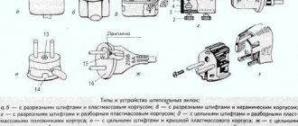
The design of electrical plugs is divided into several types. You need to familiarize yourself with the technical characteristics, advantages and disadvantages of each in more detail.
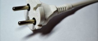
Non-removable fork device
The design features of non-separable modifications are the same everywhere. The pins are installed at intervals of 19 mm into a strip made of plastic; conductors are pressed into it. The bar is equipped with two protrusions, the purpose of which is to guide the wire. The bypass is important because it eliminates the possibility of the plug cord breaking if significant force has been applied to it.
The wire and pins are filled with molten plastic. This is ensured by a high degree of tightness of the case with the power cord securely fixed in it.
Device of a collapsible three-pole design
Not so long ago, only collapsible structures were used to connect electrical appliances. Today they are still used by a large number of Russians. You cannot do without such a part if you need to replace a cast mechanism that has failed. The advantage of such a fork is its maintainability and the ability to use it repeatedly. It can be dismantled and installed on another cord without much effort.
Design device type C1-B
This design is incredibly simple in its implementation. It consists of two halves of a plastic body, two brass pins, fasteners and a clamping bar.
Design features of the collapsible structure type C6
The design is also not particularly complicated. Modifications are available with or without a grounding contact. Designed to operate devices with a power of no more than 220 W. The pins are made of brass; contact pads with threads are pressed onto them for screwing wires. The pins are attached to the base of the plug. An additional grounding contact can be installed in the housing, which has the shape of a brass strip. There is also a strip for securely fastening the wire with a plastic gasket.
Connector A standards
Angled plug with type A connectors is used in Japan and America. In the American version, the pins have different thicknesses, in the Japanese they are the same. Another name is Class II. An Asian plug fits into an American outlet, but not vice versa. Here is an example of an American plug. If the standard of the plug or socket does not coincide with the Russian one, then adapters are used.
How to check for ground in an outlet
We figured out how to connect an outlet with grounding, but it is also advisable to understand whether the grounding works or not. To make everything official, you need to invite electricians. They will use an ohmmeter to measure grounding parameters. In general, this procedure is mandatory before putting electrical wiring into operation - today no one will connect your electricity without grounding. Moreover, grounding must meet the requirements, but no one checks it on sockets. You just need to invite electricians.
In different countries, sockets and grounding contacts have different shapes. In our country there is type F
Self check
You can check the quality of grounding in the outlet yourself. But keep in mind: all such methods are prohibited by regulatory documents. There are simply no “normal” and safe ones. There are risky ones in which you can get electrocuted. They usually check it using a tester - this is a socket with a 220 V incandescent lamp of low power (25-30 W). Two wires with a cross section of 2.5 mm² are screwed/soldered to the cartridge terminals. For convenience, you can solder crocodiles to the ends of the wires. And it’s better if they have an insulated housing - it will be easier to comply with safety precautions.
Checks using a light bulb are prohibited.
First, we determine the phase on the outlet. Even if you just connected it, double-check. This can be done using an indicator screwdriver: if the LED lights up when you touch the screwdriver probe, this is a phase. Next, we connect one of the control wires to the found phase. We touch zero with the second wire - the light should light up. When you touch the ground wire, the RCD should trip, since by your test you created a leakage current. If this happens, your grounding and RCD are working normally.
If the wiring is old and there is no RCD, the lamp will simply burn. By the brightness of its glow, you can determine whether the grounding parameters are normal or not. In theory, the brightness of the combustion when connected through zero and ground should not differ. This is if the “ground” works normally. If the brightness drops noticeably with ground, the grounding parameters are bad and it is necessary to redo it, check contacts, pins, etc.
On the issue of safety
Please note once again: it is better to invite an electrician to check the functionality of grounding in sockets. He will take measurements and give a conclusion based on the results
But if you still decide to try one of the methods of self-checking, you need to be well prepared and take all possible precautions:
Avoid touching exposed wires and metal parts with your hands.
- Place a rubber mat under your feet.
- Handle only isolated parts.
- Don't check alone. So that “if something happens” there is someone to react.
But as we have already said several times above, it is better to call an electrician. You may be able to connect a grounded outlet yourself, but it’s better to entrust the quality of the work to a professional.
If the power cord is broken
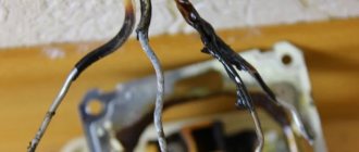
Most often, a burnt out or melted plug is only the result of a short circuit that has occurred, and the source of the problem lies in something completely different. For example, in a broken power cord. The power cable suffers after being crushed by a heavy object or externally damaged by a snag on a sharp nail or corner. Therefore, we are not in a hurry to disassemble the adapter, but carefully inspect the surface of the wire for cracks, bends or burn marks.
The easiest way to check the integrity of the cord is to use a multimeter. You just need to find the tester, switch it to “Buzzer” mode and ring the cable. If the device detects a current leak, a high-pitched squeak will be heard.
If it is necessary to test a chain longer than two meters, then an additional wire should be prepared and included in the overall circuit. When there is no spare conductor, there is another option - to twist the phase and zero at one end of the wiring. Next, connect the multimeter probes to the nearest contacts. This option has several advantages over the first one:
- you can check for leakage two wires connected in series into a single circuit at a time;
- there is no need to look for a compatible conductor and expand the circuit.
If you don’t have a multimeter at hand, you can verify the integrity of the conductor using a special homemade universal device. To make it you will need a 3.5 Volt Ilyich light bulb, a power battery (preferably a square one with a power of 4.5 Volts), two connecting wires and a gripping connector. We connect all the elements in the following sequence:
- connect a light bulb to the “plus” of the battery;
- We connect a flexible conductor with an alligator clip to the negative of the battery.
It is better to first test the resulting device on an already familiar and working section of the network. It is enough to hook the clamp anywhere, and if the circuit is assembled correctly and current flows into the wire, the light bulb will light up. If there is no glow, we make a logical conclusion that there is a leak or a wire break.
If there are doubts about the integrity of the cord and plug or there are obvious traces of melting and burning, immediate action must be taken. Knowing what to do first and how to make repairs, you can protect your life, health and property.
Share your opinion - leave a comment
How to change a plug on a wire
Repairing a power plug is not difficult, but it is very important to follow personal safety precautions while performing work.
How to disassemble an electrical plug type C1-B
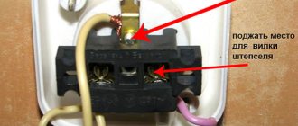
It is necessary to prepare the ends of the wires for connection. To do this, the cord is cut at intervals of no more than 5 cm from the plug. If the plug overheats due to an unreliable connection, as a rule, the insulation in these places becomes hard and must be replaced. Rings are formed at the ends of the wire. After this, spring groovers and flat washers are installed on the screws. Now this design can be inserted into the screws.
The screw must be screwed into the pin until it stops. The wire is connected to the second pin in a similar way. They are mounted with protrusions in the housing in special recesses. A strip is placed on the wire and pressed to the body using two screws. If the insulation is thin, in order to prevent it from rubbing where it exits the structure, it is recommended to put a polyvinyl chloride or rubber tube over the insulating layer.
Replacing electrical plug type C1-B
Finally, connect the halves of the housing and tighten them with a nut and screw. If the two halves of the wire are prevented from touching tightly, they need to be moved away.
How to connect a three-pole C6 plug to a wire
Preparing the wire for connection is carried out in the same way as in the previous section. The assembly technology is the same.
If the kit does not include grower plugs, they must be installed. The yellow-green wire can only be connected to the ground contact. As a rule, it is located in the middle between the contact pads of the pins.
Device
Most plugs have a standard design. They consist of a dielectric body and metal pins. Modern models that comply with the European standard provide an additional grounding contact. Such models usually have a non-separable body. Soviet-style forks are usually collapsible. However, they do not have grounding. This sharply narrows the list of devices on which they can be used.
Non-separable forks
Non-separable models are made using injection molding technology. They can often be found on extension cords. During manufacture, an electrical cable is connected to the conductive pins. Then the resulting structure is filled with liquid plastic mass. Sometimes rubber-like flexible compounds are used.
The result is a monolithic structure. It is completely sealed, so it is not afraid of a humid environment. Such a plug cannot be disassembled so that it can be used later.
Removable grounding plugs
Removable plugs with a third grounding prong are available at almost any electrical supply store. They comply with European safety requirements and allow the connection of a ground wire.
These plugs are sold assembled. The approximate price is 100-200 rubles. They are universal. They can be installed on any household appliance. Often these models have a finger ring that allows you to conveniently remove them from sockets.
Collapsible C1-B
With the advent of European standards, C1-B plugs lost their relevance. Their design is familiar to every electrician. Plug C1-B is suitable for low power devices. For example, for a fan or a table lamp.
The C1-B plug consists of a dismountable plastic housing, brass conductive pins and a pair of screws. Sometimes it is supplemented with fasteners for fixing the cable. The body consists of 2 almost identical halves. They are distinguished by the presence of holes for attaching conductive pins. There is a hole in one half, but not in the other. This point is important for ease of plug assembly. The plastic halves of the housing are secured together with a screw.
Collapsible C6
These plugs are analogous to European models CEE 7/17. They are available in both versions with and without a grounding contact. The permissible power for the C6 plug is 2.2 kW, which allows them to be used on washing machines and instantaneous water heaters. The C6 pins have an increased diameter of 4.8mm. This ensures a tighter fit in the socket slats and reliable electrical contact.
Types of plugs
Forks are divided into two main types - solid and collapsible. Their operating principle is the same; they differ only in their internal structure. The part of the plug that makes direct contact with the socket is called the pins.
Solid forks
They have pins that do not provide normal contact with old-style sockets, since their sockets do not have coil springs. They are mainly made of plastic or rubber. The pins, together with the attached cord cores, are pressed monolithically with hot plastic or rubber. Constant mechanical stress that occurs during operation can lead to loss of connection between the pin and the core.
Most modern household electrical appliances are equipped with non-dismountable plugs made of plastic. As a rule, such forks cannot be repaired. A temporary repair can be made by cutting through the fork body approximately at the location of the damage. The ends of the pin and the core are soldered to each other. After which the body together with the cut is wrapped with electrical tape. A plug repaired in this way cannot be used for a long time; it must be urgently replaced.
Collapsible forks
Based on a collapsible body. This fork can be easily disassembled and can be repaired in any way. After detecting a breakdown, first of all, its compatibility with the outlet is checked. Old plugs stop working because the wires that are secured to the pins with screws have become disconnected or loose. To hold the cord at the base of the plug, there is a metal bracket inside the housing with two screws.
The housing is disassembled by unscrewing the central screw that holds its parts together. After this, you can check the quality of the connection of the cores. To repair the damage, the core of the cord is connected in a loop to a pin, which is then fixed in the cavity of the housing. Using the depressions, the required distance is maintained between both pins, coinciding with the sockets.
It should be remembered that a poorly secured loop on the pin first of all causes the body to heat up, even to the point of melting the plastic. In this case, the housing must be replaced.
Thus, the question of how to repair or replace a power plug is quite simple and does not require any special skills or special knowledge.
Grounding and zeroing: what is the difference
One of the common installation mistakes is when connecting an outlet with grounding is done by using the “0” two-wire network. This method is called “zeroing” in the language of electricians. When implementing it, “0” is used as both a protective and zero working contact.
The desired effect is achieved by installing a jumper from the “neutral” to the “ground”; but this installation method contradicts the requirements of the PUE
But grounding is not an equivalent alternative to grounding. After all, a line cannot protect itself from itself.
So, for example, if “0” disappears as a result of the same cable break on the input panel or rash actions of an unqualified “craftsman,” the circuit is closed at the moment the device is turned on. But at the same time, the same voltage appears on the neutral wire, which is essentially not connected to the ground, as on the phase wire.
As a consequence: an electrical installation that is grounded by grounding and becomes energized transmits it to a person. The most favorable outcome in this situation is if a short circuit occurs, which causes the machine to “knock out.” Otherwise, the price of such zeroing can become deplorable.
It is also worth considering the fact that according to the technology for installing indoor electrical wiring, packets or two-pole circuit breakers are installed at the input, which switch both “phase” and “0”.
According to accepted standards, in a circuit where there is a switching device, it is prohibited to use the neutral conductor as a protective conductor.
Old electrical plug and its replacement
The old electrical plug has a simpler design. Here the replacement technique will be slightly different. Here are the main steps you will need to complete:
First, you need to cut off the old electrical plug housing and disassemble it.
As with the Euro plug, you need to expose the wires. The ends should be stripped to 15 cm of the wire. The design of a regular plug may differ, which is why it is necessary to strip the wires, as indicated in the photo below.
There is no grounding here, so you only need to connect two wires
When connecting, be sure to pay attention to the polarity
Now you can begin assembling the electrical plug housing.
As you can see, the old electrical plug has a simple assembly design. You can see how to do this in the video below. If your washing machine is noisy, then you should read about this problem.
