Current problems mainly deal with determining current, voltage, and resistance. In this section you will find formulas for solving problems. We will look at solving typical elementary problems using Ohm's law.
An electric charge equal to 30 C passes through the filament of a flashlight bulb in 2 minutes. Determine the current in this light bulb.
| Given: | SI | Solution |
| q = 30 C | The current strength I is determined by the formula | |
| t = 2 min | 120 s | I= q/t |
| I – ? | I = 30Kl/120s = 0.25A = 250mA |
Current strength. Problem solving
Expert opinion
It-Technology, Electrical power and electronics specialist
Ask questions to the “Specialist for modernization of energy generation systems”
How to find voltage through EMF and resistance? In this graph, the resistance of the conductors in ohms is plotted along the horizontal axis on a conventionally selected scale, and the current in amperes is plotted along the vertical axis. Ask, I'm in touch!
Meaning of Ohm's Law
Ohm's law determines the current strength in an electrical circuit at a given voltage and known resistance.
It allows you to calculate the thermal, chemical and magnetic effects of current, as they depend on the strength of the current. Ohm's Law is extremely useful in engineering (electronic/electrical) because it deals with three basic electrical quantities: current, voltage and resistance. It shows how these three quantities are interdependent at the macroscopic level.
If it were possible to characterize Ohm's law in simple words, then it would clearly look like this:
It follows from Ohm's law that it is dangerous to close a conventional lighting network with a conductor of low resistance. The current will be so strong that it can have serious consequences.
Problem 1.1
Calculate the current passing through a copper wire 100 m long, with a cross-sectional area of 0.5 mm2, if a voltage of 12 V is applied to the ends of the wire.
The task is simple; it consists in finding the resistance of a copper wire and then calculating the current strength using the Ohm's law formula for a section of the circuit. Let's get started.
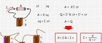
Ohm's law for a complete circuit
The formulation of Ohm's law for a complete circuit is that the current strength is directly proportional to the sum of the EMF of the circuit, and inversely proportional to the sum of the source and circuit resistances, where E is the EMF, R is the circuit resistance, r is the internal resistance of the source.
Questions may arise here. For example, what is EMF?
Electromotive force is a physical quantity that characterizes the work of external forces in an EMF source. For example, in a regular AA battery, EMF is a chemical reaction that causes charges to move from one pole to the other. The word electromotive itself means that this force moves a charge.
Each source has an internal resistance r, it depends on the parameters of the source itself. There is also a resistance R in the circuit; it depends on the parameters of the circuit itself.
The formula for Ohm's law for a complete chain can be presented in another form. Namely: the EMF of the circuit source is equal to the sum of the voltage drops on the source and on the external circuit.
To consolidate the material, we will solve two problems using the formula of Ohm's law for a complete circuit.
Problem 2.1
Find the current strength in the circuit if it is known that the circuit resistance is 11 ohms, and the source connected to it has an emf of 12 V and an internal resistance of 1 ohm.
Now let's solve a more difficult problem.
Problem 2.2
The EMF source is connected to a 10 ohm resistor using a copper wire 1 m long and with a cross-sectional area of 1 mm2. Find the current strength, knowing that the source emf is 12 V and the internal resistance is 1.9825 Ohms.
Let's get started.
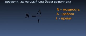
Calculation of the power of an electrical appliance based on current consumption
Knowing the current value, you can determine the power consumption of any electrical energy consumer, be it a light bulb in a car or an air conditioner in an apartment. It is enough to use a simple law of physics, which was established simultaneously by two physicists, independently of each other. In 1841 James Joule, and in 1842 Emil Lenz. This law was named after them - the Joule-Lenz Law
.
where P
is power, measured in watts and denoted by
W
;
U
– voltage, measured in volts and denoted by the letter
B
;
I
– current strength, measured in amperes and denoted by the
letter A.
Let's look at how to calculate power consumption using an example: You measured the current consumption of a car headlight bulb, which was 5 A, the on-board voltage is 12 V. This means that to find the power consumption of a light bulb, you need to multiply the voltage by the current. P=12 V×5 A=60 W. The power consumption of the light bulb was 60 W.
| Online calculator to determine power consumption |
| Voltage, V: |
| Current strength, A: |
You need to determine the power consumption of the washing machine. You measured the current consumption, which was 10 A, therefore, the power will be: 220 V × 10 A = 2.2 kW. As you can see, everything is very simple.
| Online calculator for determining current strength by power consumption |
| Power consumption, W: |
| Supply voltage, V: |
Electrical circuit
A source of electric current connected by wires to various electrical appliances and consumers of electrical energy forms an electrical circuit.
It is customary to depict an electrical circuit using diagrams in which the elements of the electrical circuit (resistances, current sources, switches, lamps, devices, etc.) are indicated with special icons.
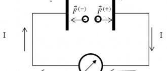
The direction of current in a circuit is the direction from the positive pole of the current source to the negative pole. This rule was established in the 19th century. and has been observed ever since. The movement of real charges may not coincide with the conventional direction of the current. Thus, in metals, current carriers are negatively charged electrons, and they move from the negative pole to the positive one, that is, in the opposite direction. In electrolytes, the actual movement of charges may coincide with or be opposite to the direction of the current, depending on whether the ions are charge carriers - positive or negative.
The inclusion of elements in an electrical circuit can be serial or parallel.
Ohm's law for a circuit
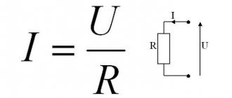
Ohm’s law for a section of a circuit can, of course, be described by the formula known from a school physics course: I=U/R, but I think it’s worth making some changes and clarifications. Let's take a closed electrical circuit and consider its section between points 1-2. For simplicity, I took a section of the electrical circuit that did not contain sources of emf (E).
So, Ohm's law for the section of the circuit under consideration has the form:
φ1-φ2=I*R, where
- I – current flowing through a section of the circuit.
- R is the resistance of this section.
- φ1-φ2 – potential difference between points 1-2.
If we take into account that the potential difference is voltage, then we come to the derivative formula of Ohm's law, which is given at the beginning of the page: U=I*R. This is the formula of Ohm's law for the passive section of the circuit (containing no sources of electricity).
Interesting on the topic: How to check a zener diode.
In an unbranched electrical circuit (Fig. 2), the current strength in all sections is the same, and the voltage in any section is determined by its resistance:
- U1=I*R1
- U2=I*R2
- Un=I*Rn
- U=I*(R1+R2+…+Rn
From here you can obtain formulas that are useful in practical calculations. For example:
U=U1+U2+…+Un or U1/U2/…/Un=R1/R2/…/Rn
The calculation of complex (branched) circuits is carried out using Kirchhoff's laws.
Ohm's law for a section of a circuit.
For EMF
Before considering Ohm's law for a complete (closed) circuit, I will give a sign rule for EMF, which states:
If inside an EMF source the current flows from the cathode (-) to the anode (+) (the direction of the field strength of external forces coincides with the direction of the current in the circuit, then the EMF of such a source is considered positive. Otherwise, the EMF is considered negative.
A practical application of this rule is the possibility of bringing several sources of EMF in a circuit to one with the value E=E1+E2+…+En, naturally, taking into account the signs determined by the above rule. For example (Fig. 3.3) E=E1+E2-E3. In the absence of a back-to-back source E3 (in practice this almost never happens), we have a widespread serial connection of batteries, in which their voltages are summed.
Tags
- algorithm for calculating circuits under non-sinusoidal periodic influences
- algorithm for calculating circuits of periodic non-sinusoidal current
- power balance
- CVC of a nonlinear element
- Vector diagram
- branches of communication
- mutual inductance
- mutual conductivity
- current-voltage characteristic of a nonlinear element
- Kirchhoff's second law
- Kirchhoff's second law for magnetic circuits
- input conductance
- voltage harmonics
- current harmonics
- Voltage generator
- current generator
- main contours
- graphical method for calculating nonlinear electrical circuits
- dynamic resistance
- differential resistance
- two-wire line capacity
- coaxial cable capacity
- capacitor capacity
- single wire line capacity
- parallel plate capacitor capacitance
- cylindrical capacitance
- Ampere's law
- Biot-Savart-Laplace's law
- Ohm's law
- total current law
- law of electromagnetic induction
- Kirchhoff's laws
- inductance
- two-wire line inductance
- single wire line inductance
- solenoid inductance
- steel reel
- Capacitor in DC circuit
- loop currents
- crest factor
- harmonic distortion factor
- distortion factor
- magnetic coupling coefficient
- transformer power factor
- transformation ratio
- form factor
- piecewise linear approximation
- magnetic constant
- magnetic circuit
- magnetic leakage flux
- active two-terminal method
- two node method
- loop current method
- overlay method
- nodal stress method
- nodal potential method
- equivalent generator method
- EMF equivalent source method
- Equivalent transformation method
- methods for calculating magnetic circuits
- independent circuits
- nonlinear element
- non-sinusoidal periodic current
- generalized Ohm's law
- support node
- main magnetic flux
- parallel connection of capacitors
- Kirchhoff's first law
- Kirchhoff's first law for magnetic circuits
- series connection of capacitors
- series oscillating circuit
- DC current component
- copper losses
- steel losses
- led transformer
- Examples of circuit calculations for non-sinusoidal periodic influences
- principle of reciprocity
- principle of compensation
- current harmonics calculation
- magnetic circuit calculation
- calculation of nonlinear DC circuits
- calculation of non-sinusoidal current circuits
- Capacitor circuit calculation
- calculation of a circuit with non-sinusoidal periodic sources
- Resonance in an electrical circuit
- problem solving magnetic circuits
- Ampere power
- Lorentz force
- Symbolic method
- intrinsic conductivity
- static resistance
- spherical capacitor
- equivalent source theorem
- Thevenin's theorem
- topographic diagram
- Transformers
- three phase system
- specific magnetic field energy
- transformer equations
- Circuits with capacitors
- partial currents
- phase rotation
- Self-induced emf
- transformer equivalent circuit
- electrical constant
- electrical capacity
- magnetic field energy
Serial and parallel connection of elements
For elements of an electrical circuit (section of a circuit), a characteristic point is a serial or parallel connection. Accordingly, each type of connection is accompanied by a different pattern of current flow and voltage supply. In this regard, Ohm's law is also applied differently, depending on the option of including elements.
Circuit of series-connected resistive elements
In relation to a series connection (a section of a circuit with two components), the following formulation is used:
- I = I1= I2 ;
- U = U1+ U2 ;
- R = R1+ R2
This formulation clearly demonstrates that, regardless of the number of resistive components connected in series, the current flowing through a section of the circuit does not change in value. The magnitude of the voltage applied to the effective resistive components of the circuit is the sum and totals the value of the emf source.
In this case, the voltage on each individual component is equal to: Ux = I * Rx. The total resistance should be considered the sum of the values of all resistive components in the circuit.
Circuit of parallel connected resistive elements
In the case when there is a parallel connection of resistive components, the following formulation is considered fair in relation to the law of the German physicist Ohm:
- I = I1+ I2 … ;
- U = U1= U2 … ;
- 1 / R = 1 / R1+ 1 / R2 + …
Options for creating circuit sections of a “mixed” type, when parallel and serial connections are used, are not excluded. For such options, the calculation is usually carried out by initially calculating the resistive rating of the parallel connection. Then the value of the resistor connected in series is added to the result obtained.
Capacitance
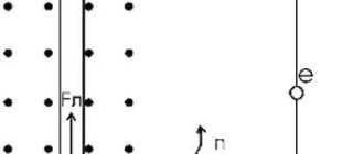
Let us assume that a capacitor of capacitance $C$ is included in a section of the circuit, and $R=0$ and $L=0$. We will consider the current strength ($I$) to be positive if it has the direction indicated in Fig. 2. Let the charge on the capacitor be equal to $q$.
Figure 2.
We can use the following relationships:
If $I(t)$ is defined by equation (1), then the charge is expressed as:
where $q_0$ is an arbitrary constant charge of the capacitor, which is not associated with current fluctuations, so we can assume that $q_0=0.$ We obtain the voltage equal to:
Formula (6) shows that voltage fluctuations on a capacitor lag behind current fluctuations in phase by $frac{pi }{2}.$ The voltage amplitude across the capacitor is equal to:
The quantity $X_C=frac{1}{omega C}$ is called reactive capacitance (capacitance, apparent resistance of a capacitance). If the current is constant, then $X_C=infty $. This means that no direct current flows through the capacitor. From the definition of capacitance it is clear that at high oscillation frequencies, small capacitances are small resistances to alternating current.
Do you need advice on your academic work? Ask your teacher a question and get an answer in 15 minutes! Ask a Question
Third party force
Nevertheless, current flows through the circuit; therefore, there is a force that “pulls” the charge through the source despite the resistance of the electric field of the terminals (Fig. 1).
Rice. 1. Third party force
This force is called a third party force; It is thanks to it that the current source functions. Third party force
has no relation to a stationary electric field - it is said to have a non-electric origin; in batteries, for example, it arises due to the occurrence of appropriate chemical reactions.
Let us denote by
the work of an external force to move a positive charge q inside a current source from the negative terminal to the positive. This work is positive, since the direction of the external force coincides with the direction of charge movement. The work of an external force is also called the work of a current source.
There is no external force in the external circuit, so the work done by the external force to move the charge in the external circuit is zero. Therefore, the work of an external force to move the charge
around the entire circuit comes down to the work of moving this charge only inside the current source. Thus, this is also the work of an external force to move charge throughout the circuit.
We see that the external force is non-potential - its work when moving a charge along a closed path is not zero. It is this non-potentiality that allows the electric current to circulate; a potential electric field, as we said earlier, cannot support a constant current.
Experience shows that work
directly proportional to the charge being moved. Therefore, the ratio no longer depends on the charge and is a quantitative characteristic of the current source. This relationship is denoted by: (1)
This quantity is called the electromotive force (EMF) of the current source. As you can see, EMF is measured in volts (V), so the name “electromotive force” is extremely unfortunate. But it has long been ingrained, so you have to come to terms with it.
When you see the inscription on the battery: “1.5 V”, then know that this is exactly the EMF. Is this value equal to the voltage created by the battery in the external circuit? It turns out not! Now we will understand why.
How to measure current consumption of an electrical appliance
For the convenience and safety of measuring current consumption by electrical appliances, it is necessary to make a special extension cord with two sockets. In appearance, a homemade extension cord is no different from an ordinary extension cord.
But if you remove the covers from the sockets, it is not difficult to notice that their terminals are connected not in parallel, as in all extension cords, but in series.
As you can see in the photo, the mains voltage is supplied to the lower terminals of the sockets, and the upper terminals are connected to each other by a jumper made of wire with yellow insulation.
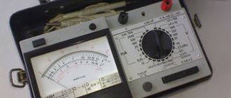
Everything is ready for measurement. Insert the plug of the electrical appliance into any of the sockets, and the ammeter probes into the other socket. Before measurements, it is necessary to set the device switches in accordance with the type of current (AC or DC) and to the maximum measurement limit.
As can be seen from the ammeter readings, the current consumption of the device was 0.25 A. If the device scale does not allow direct reading, as in my case, then it is necessary to calculate the results, which is very inconvenient. Since the ammeter measurement limit is 0.5 A, to find out the division value, you need to divide 0.5 A by the number of divisions on the scale. For this ammeter it turns out 0.5/100=0.005 A. The needle has deviated by 50 divisions. So now you need 0.005×50=0.25 A.
As you can see, taking current readings from pointer instruments is inconvenient and you can easily make a mistake. It is much more convenient to use digital instruments, such as the M890G multimeter.
The photo shows a universal multimeter turned on in the AC current measurement mode to a limit of 10 A. The measured current consumed by the electrical device was 5.1 A at a supply voltage of 220 V. Therefore, the device consumes 1122 W of power.
The multimeter has two sectors for measuring current, designated by the letters A–
for direct current and
A~
for measuring alternating current. Therefore, before starting measurements, you need to determine the type of current, estimate its magnitude and set the switch pointer to the appropriate position.
Multimeter socket labeled COM
is common to all types of measurements.
Sockets marked mA
and
10A
are intended only for connecting a probe when measuring current.
For a measured current of less than 200 mA, the probe plug is inserted into a mA socket, and for a current of up to 10 A, into a 10 A socket.
Attention, if you measure a current that is many times greater than 200 mA when the probe plug is in the mA socket, the multimeter can be damaged. If the magnitude of the measured current is not known, then measurements must be started by setting the measurement limit to 10 A
If the current is less than 200 mA, then switch the device to the appropriate position. Switching multimeter measurement modes can only be done by de-energizing the circuit being measured.
If the value of the measured current is not known, then measurements should be started by setting the measurement limit to 10 A. If the current is less than 200 mA, then switch the device to the appropriate position. Switching multimeter measurement modes can only be done by de-energizing the circuit being measured.
.
Electrical circuit efficiency
It is not difficult to understand why the resistor
called the payload. Imagine it's a light bulb. The heat generated by the light bulb is useful, since thanks to this heat the light bulb fulfills its purpose - giving light.
The amount of heat released by the payload
for time, let's denote .
If the current in the circuit is equal to
, That
A certain amount of heat is also released at the current source:
The total amount of heat released in the circuit is equal to:
The efficiency of an electrical circuit is the ratio of useful heat to total heat:
The efficiency of the circuit is equal to unity only if the current source is ideal
.
Where and when can Ohm's law be applied?
Ohm's law in the form mentioned is valid within fairly wide limits for metals. It is carried out until the metal begins to melt. A less wide range of applications is in solutions (melts) of electrolytes and in highly ionized gases (plasma).
When working with electrical circuits, sometimes you need to determine the voltage drop across a certain element. If it is a resistor with a known resistance value (it is marked on the case), and the current passing through it is also known, you can find out the voltage using Ohm’s formula without connecting a voltmeter.
Sources
- https://toe.1c-umi.ru/lekcii/lekciya_6_-_zakon_oma/
- https://www.calc.ru/Zakon-Oma-Dlya-Polnoy-Elektricheskoy-Tsepi.html
- https://ElectroInfo.net/teorija/vse-o-zakone-oma-prostymi-slovami-s-primerami-dlja-chajnikov.html
- https://ege-study.ru/ru/ege/materialy/fizika/eds-zakon-oma-dlya-polnoj-cepi/
- https://OFaze.ru/teoriya/zakona-oma-dlya-polnoj-tsepi