In an area of uncertain reception of a television signal, in order to obtain a high-quality picture when watching television, you have to install an external antenna on the mast, on the vibrator of which an antenna amplifier is additionally installed. Installing an additional amplifier ensures a high-quality picture on the TV when the TV transmission tower is up to 100 km away.
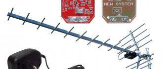
Antenna amplifiers of the SWA line have become widespread due to their high reliability and low price. They are produced for different channel ranges and different gain factors, from 34 to 43 dB in the UHF range and from 10 to 15 dB in the meter range. The photo shows an amplifier type SWA-555/LUX.
The SWA television signal antenna amplifier must be powered with a constant voltage of 12 V. There is a circuit solution that allows supply voltage to the television amplifier via a coaxial cable simultaneously with the television signal. The photo shows how to connect a television wire to the SWA antenna amplifier.
The central core is clamped with one screw, and the shielding wire is stripped of insulation, wrapped and clamped with screws using a strip. The main thing here is to prevent the screen wires from shorting out with the central core. In this way, antenna amplifiers of any type installed directly on the antenna are connected.
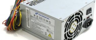
There are special power supplies on sale - adapters with adapters that allow you to supply power to the antenna amplifier. The photo shows one of them. Connecting such an adapter is simple; the cable coming from the antenna is inserted into one coaxial wire, and the cable going to the TV is inserted into the second. The adapter itself is plugged into the socket. It is impossible to mix up the wires when connecting; the coaxial wires coming out of the adapter have different connectors, which prevents erroneous connections.
Power supply - adapter for antenna amplifier
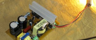
If you open any power supply with an adapter, you will see a power transformer, four diodes, an electrolytic capacitor, a simple capacitor, a choke and a voltage stabilizer microcircuit.
All parts of the decoupling circuit, except the power transformer, are installed on the printed circuit board.
Electrical circuit diagram of the power supply for the antenna amplifier with adapter
The power supply shown above in the photo - an adapter for powering the antenna amplifier - is assembled according to a classic electrical circuit diagram. AC mains voltage 220 V is supplied to power transformer T1, which lowers it to 12-15 V. The diode bridge VD1-VD4 rectifies the voltage, the electrolytic capacitor C1 smoothes out the ripples, after which a constant voltage of about 16 V is supplied to the integrated voltage stabilizer DA1.
To eliminate video signal losses and loss of DC voltage, an LC filter is provided at the input of the television receiver, made on elements L1 and C3. Choke L1 does not pass a high-frequency television signal to the power supply circuit, but without losses it allows direct current to flow to the central core of the television cable coming from the television antenna amplifier. Capacitor C3 prevents DC current from flowing from the power supply to the TV input, but passes the TV signal without loss.
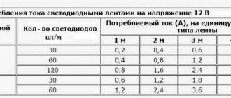
When making your own power supply with an adapter, parts can be used of any type. Typically, the current consumption of antenna amplifiers does not exceed 150 mA, which is less than 2 watts, so the transformer for the power supply is suitable for any power with an output voltage of 15-18 V. The choke can be made by winding it on a dielectric base, for example, a strip of fiberglass 5 mm wide, 25-18 V. 30 turns of enameled copper wire with a diameter of 0.1-0.5 mm.
Disadvantages of the presented design of the power supply with adapter
The disadvantages of a power supply adapter of this design include the presence of an unshielded section of the central core of the television cable at the place where it is sealed into the printed circuit board, which, in the presence of interference, for example from a working vacuum cleaner, can lead to interference with the video signal. The penetration of interference can be eliminated by installing an additional shield on the printed circuit board at the place where the wires are soldered.
What are the features
When it comes to choosing between a passive and active antenna, it is enough to remember the operating features and advantages of the latter.
We have already figured out that each antenna is capable of catching an incoming signal. Another thing is to convert it and make it powerful enough for ideal sound quality. This task is performed by the amplifier, which is equipped with active antennas. The quality and strength of the signal largely depends on a number of factors - the distance to the signal source, the terrain, and so on. For example, if the area around is flat, the signal will arrive without any interference. If there are hills or mountains, the quality may deteriorate. Having an amplifier built into the antenna can correct the problem. At the same time, the sound is of high quality at different signal strengths.
Video: Review of parcels from China Active internal car antenna amplifier
By the way, passive antennas are not always effective even in city conditions. A large number of concrete buildings with metal reinforcement at the base - all this is an obstacle to the signal and can deteriorate the sound quality, causing unnecessary noise. The active car antenna copes with the task “excellently” here too.
Another nuance is tinting. A simple car film contains a metal coating, which acts as a screen for the signal. If your car has a passive indoor antenna, you may not get good sound. Of course, if the receiving device is located outside, then such problems due to tinting are excluded. In the case of an active antenna, you can safely tint the car and install the device in the cabin - the signal quality will always be decent.
Design and diagram of the crab
The TV crab is a metal box with F-connectors. Inside, on the central terminals of the connectors, parts (high-frequency transformers) of the television signal splitter are soldered. A high-frequency transformer is shaped like a ring or tube made of ferrite with a magnetic permeability of 600-2000, on which 1 to 10 turns of enameled wire with a diameter of 0.2-0.3 mm are wound, evenly spaced around the entire circumference.
In the photograph of the crab from which the back cover has been removed, you can clearly see how the ferrite transformers are wired for connecting three TVs. This crab is assembled according to the Electrical Circuit Diagram below.
All produced crabs are assembled according to the given electrical circuit diagram; there may be minor deviations - additional separating and filtering capacitors, chokes, and matching resistors are installed.
Review of popular active car antennas
If you choose from simple, high-quality and budget antennas, then a good option is the Triad antenna. Its advantage is full adaptation to operating conditions in Russia and the maximum range of received signals. At the same time, you can find five different types of such antennas on the market. There is no point in dwelling on all of them - let’s look at the advantages of the most popular model - “610 Standard”. Many experts put the antenna on a par with such giants as Prologi or Pioneer.
Active antenna Triad “610 Standard”
The main advantages of the Triad antenna include:
- reduction of interference from the ignition system due to the presence of a double filter in the power system;
- the presence of a powerful amplifier capable of optimizing wave signals of various lengths (UHF and MV);
- additional operating modes – “turbo” and “city”. The first option must be activated when driving outside the city, where the signal is quite weak and needs to be strengthened. The second mode (“city”) is suitable for use in populated areas when the signal quality is high enough.
The Triad 610 “Standard” antenna is equipped with a special radio splitter, with which you can enjoy high-quality reception of television and radio signals.
Another popular device is the “Scat” antenna (installed inside the cabin). Unlike the previous device, this antenna is aimed exclusively at receiving radio signals. Product manufacturer – . The peculiarity of the antenna is the minimum configuration and sale in already assembled form. This is very convenient, because all that is required of the car enthusiast is to mount the device on the windshield.
The main advantage of the Skat model is metal vibrators on the canvas, which are increasingly used on prestigious antennas
When installing the device, no special skills are required - only caution and accuracy. A napkin is included for cleaning the installation site.
Automotive active antenna "Scat"
Among the main technical parameters it is worth highlighting:
- high-quality antenna assembly made using industrial methods;
- high-frequency Telefunken microcircuit, which is the main active element and ensures high-quality signal reception;
- two operating modes – for weak and strong signals;
- the presence of moisture protection, which guarantees the operation of the device for ten years or more;
- operability at reduced voltage to seven volts;
- A high-quality filter allows you to connect and configure the antenna with any radio.
Conclusion
Buying an active car antenna is the best option for a car enthusiast. These devices are reliable and easy to set up, and most importantly, they provide a high-quality signal.
How to make your own adapter for supplying power to an antenna amplifier
When making an adapter for supplying power to an isolated antenna amplifier, I decided not to install an additional connector for connecting the power supply, but to use one of the connectors for connecting the F-plug. To do this, we had to remove one of the transformers, limiting the crab's ability to connect only two TVs.
As a result of the modification, only two TVs can be connected to the crab, and its circuitry has changed.
All that remains is to install the LC filter in the crab and the adapter will be ready for use. Since the crab body is made of duralumin, the capacitor lead had to be connected to it through an additionally installed brass terminal, screwed to the adapter body using a screw and nut with a shaped washer.
As a result of the modification, the electrical circuit diagram of the crab acquired the following form. As can be seen from the diagram, transformer T1 remained original, but a choke and two capacitors were added.
To better match the circuit, you can solder a 150 Ohm resistor between the output pins XW2 and XW3. You can install the adapter in any convenient place, directly next to one of the TVs, or, for example, at the cable entrance to the apartment. If you need to connect only one TV, then transformer T1 can be removed, and the right terminal of capacitor C1 can be soldered directly to the central terminal of one of the connectors XW2 or XW3, to which the cable going to the TV can be connected.
DIY car antenna.
Dop-AvtoService Blog How to properly install and connect an amplifier
When you return from the store with a new purchase, be sure to read the manufacturer’s instructions before installation. Surely, there you will find recommendations on where to install this device, and there should also be a connection diagram to the car’s audio system.
Connecting a passive antenna.
If this is a regular passive antenna, then you will have to run a cable from the place where it is attached to the place where it is connected. If you want high-quality antenna performance, then the cable must be shielded braided. If the manufacturer saved money and included a regular one in the kit, and even a shorter one than necessary, well, you’ll have to go to the store again.
When laying the cable, remember that its length should be as short as possible, so that there are no unnecessary twists of its remains near the connection points. Also, do not strain the cable, since such an arrangement can lead to its rapid failure.
If you need to connect two sections of cable, which, of course, is not advisable (it is better to purchase one of the required length), then these sections must be securely connected and soldered; connecting the cables is also possible through special plugs.
The antenna wire input to the car's audio system must also be made using a plug. Many people are sometimes too lazy to bother with attaching the plug, and they simply insert the stripped end into the connection socket. This scheme is unacceptable. Later, it will remind itself of the poor performance of the antenna, since due to vibration and oxidation such contact will be very unreliable. So spend a little time and get the job done.
Attaching a car antenna to the car body.
So, we also sorted out the connection. Now let's move on directly to attaching the antenna to the car body. You can read in detail about the installation location and the mounting methods themselves in the installation instructions. I'll just give you a couple of tips.
First, securely mount the antenna. Remember, at high speeds, if it is poorly secured, air currents can very easily tear off your antenna. Secondly, if you need to make a hole (one or more) to install the antenna, then waterproof it well. If this moment is missed, corrosion of the body and damage to the paintwork can very quickly begin in this place. By the way, be very careful when installing antennas that are mounted on magnets; remember, in order not to damage the paintwork, there should be no dust or dirt under the installation site, and the magnet itself should be covered with a material that avoids damage to the body. Thirdly, internal antennas, for the most part, are mounted on top of the windshield or rear window
When installing them, make sure that they do not impair your visibility. After all, a good overview is, first of all, your safety and the safety of your passengers.
In addition, try to hide the wires coming from such an antenna under the interior trim elements. Because wires rattling on uneven roads and dangling all over the windshield will greatly distract attention from the road and also impair visibility. Directly attaching the antenna itself won’t take much work. They attach it with double-sided tape, which almost always comes with the antenna. But under no circumstances glue the antenna with super glue; such an imaginary improvement in some cases, due to temperature changes, will lead to cracking of the windshield in the places of gluing. Do you need these extra problems?!
In principle, that’s probably all about car antennas. Yes, of course, today I focused only on car antennas for connecting to car audio systems, but in addition to them, antennas can also be installed for GSM communications, GPS communications and much more. They also have their own nuances, but the essence of their installation remains unchanged. Understanding the connection diagram of conventional antennas, it will not be difficult for you to connect any other antenna yourself, having only the manufacturer’s instructions available. Good luck!
Video
Connecting the power supply to the adapter
Since I decided to connect the power supply to the crab through one of its F-connectors, to implement this idea I had to make an adapter from an ordinary double wire coming from the power supply to a coaxial cable.
To do this, you need to take a piece of antenna cable 5 cm long, cut one end of it and put on an F-wrap. To the second end, as shown in the photographs, solder the wires coming from the power supply with a shift. The positive terminal is soldered to the central core of the antenna cable.
If you don’t want to mess around, you can install a standard connector in the crab body for connecting power supplies and through it supply voltage to the antenna amplifier through a home-made adapter.
Satellite TV
In order for the antenna amplifier installed in the “Polish Grid” antenna housing to work, it must be connected to a power source. The amplifier is powered via a coaxial cable running from the antenna to the TV. This means we need to connect the power supply to this cable. Many users find it difficult to do this. Let's consider a simple connection option.
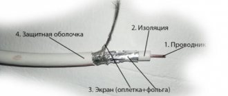
| The power supply is a converter of high voltage household electricity to low voltage. This voltage is used to provide power to the electrical circuit components. It also serves to stabilize and protect the supply voltage. |
First you need to cut the end of the television cable (more about cutting the cable). We step back 1.5 cm from the end of the cable and carefully remove the outer insulation, trying not to damage the screen and the insulation of the central core. Remove the outer shell cut in a circle. Then we move the hairs of the screen and the foil back. Next, we retreat 0.5 cm from the moved braid and cut off the inner insulation from the central core in a circle. The cable is ready for connection.
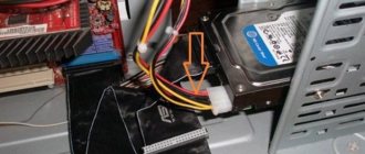
Carefully place the cut cable into a special fastener on the power supply separator board. It is necessary that the cable braid tightly touches the lower contact pad, and the central core is inserted into the screw retainer.
We tighten the screws until the cable contacts are completely fixed.
| It is necessary to ensure that the central core and the braid do not touch under any circumstances, otherwise we will get a short circuit and the system will not work. In this case, the indicator on the power supply will light very dimly or not light at all. You also need to ensure that the braid is in close contact with the pad on the board. Otherwise, the voltage may not flow through the cable. |
If connected correctly, the TV will begin to show channels when scanning and tuning them. If you turn off the power supply, the image may deteriorate or disappear altogether.
Happy connection!
9, total, today
Please give us your valuable comments
digitalsattv.ru
Selecting the size of output transistors
The size of the output transistors is selected to optimize heat dissipation in all operating modes. In order for the voltage on the transistor Vt to be small at a high current It, the transistor must have a small resistance in the on state, Ron (usually 0.1 or 0.2 Ohm).
This requires large transistors, with large gate capacitance (CG). The power consumed by the gate control circuits is CU2f, where C is the capacitance, U is the change in voltage when switching transistors, f is the switching frequency. Switching losses become large if the capacitance or frequency is high, so there is a practical upper limit. The choice of transistor size is a compromise between Vt x It losses and switching losses.
Resistive losses will dominate at high output power, switching losses will dominate at low output power. Power transistor manufacturers try to minimize the Ron x CG product to reduce the overall power dissipation of the transistor switches and provide flexibility in selecting the switching frequency.
How to boost a TV antenna signal with your own hands
How to improve/strengthen a TV antenna? You can install a TV signal amplifier for an outdoor antenna in your dacha yourself, following some recommendations and tips. Use silicone for coating, it will make the board airtight. Choose a good quality connection cable. It must be securely attached to the match. Outdoor televisions must be mounted on the roof or roofing using matches. Matcha should not be made very high. No matter how surprised you are, the amplifier is powered by a power supply. It can be external, but it can also be internal. Therefore, it is necessary to ensure a connection to the electrical network. Many people advise using with an external connection, because they will ensure a stable supply of current without a voltage drop. As for mounting the amplifier itself, it is mounted using bolts. After all the settings, you can connect the cable to the TV and proceed to setting up TV channels and antenna. If you are wondering how to connect correctly, then there is no difficulty in this; the cable is connected to the TV in the same way as from a regular indoor TV antenna. How to check whether the design works or not? Connect the cable to the TV, go to the menu, namely the TV channel search item. And use manual or auto search. If the image and sound appear, channels are found, then you did everything correctly. Also, a powerful indoor TV antenna can provide excellent reception of radio waves in the country if there is a TV tower within a radius of a couple of kilometers.
On the pages of Internet resources, you will find a large number of videos, as well as detailed diagrams of how you can independently make such an important part for your dacha. Such modern technological solutions to eliminating bad radio signals allow you to watch TV without interference and keep abreast of the latest world news. A large assortment for choosing different models with a variety of technical characteristics is suitable for almost all modern and not so modern TV antennas. The coordinated work of the two devices will allow you to watch familiar TV channels in excellent quality.