01/12/18
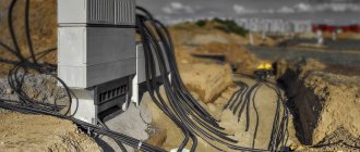
High-voltage cable lines (CL) are exposed to weight and soil shifts, temperature changes and other external factors. Testing cable lines with high voltage allows you to check the condition of the insulating layer and promptly replace damaged areas. Regularly conducting such checks is a necessary condition for the trouble-free operation of cable lines and helps prevent accidents, property damage and other unpleasant consequences.
Testing of 10 kV high voltage cable is required:
- after laying or replacing the cable - before filling the trench and turning on the power line;
- in relation to used cable lines - after a long outage and scheduled or unscheduled repairs;
- in relation to the cable sheath, which is laid in the ground and operates without electrical breakdowns - with a frequency of 5 years;
- for main cable lines - with an interval of 3 years;
- for reserves - with a 5-year frequency;
- for main and reserve cable lines supplying facilities of special importance - annually.
When carrying out excavation work, landslides, sedimentation or erosion of soil, extraordinary tests of cable lines are required. Additional checks are carried out upon completion of work.
Engineering has all the necessary licenses for testing high-voltage cables, a well-coordinated team of professionals and certificates that give the right to carry out all the necessary tests and measurements. By choosing the ProfEnergia electrical laboratory, you are choosing reliable and high-quality operation of your equipment!
If you want to order high-voltage tests, as well as for other questions, call: +7 (495) 181-50-34.
Test conditions
High voltage testing of power cables must be carried out by competent personnel who are at least 18 years of age and have undergone appropriate training. First, the CLs are inspected to identify defects in the insulating layer. Significant contamination is removed from the surface. The funnels are wiped clean.
The permissible air temperature for testing work is from 0 °C. First of all, the resistance of the cable insulation coating is measured with a megger. The required high voltage resistance is not lower than 1 MOhm. Such measurements make it possible to detect significant defects, violations of integrity and errors made during repair activities.
Insulation resistance is measured as follows:
1. Using an increased voltage device, check whether the cable is de-energized.
2. Grounding with clamps is installed on the cable cores.
3. On the opposite side, the cable outlets are left free. Warnings are placed here or a supervisory person is left to avoid accidental passers-by becoming energized.
4. Insulation resistance is measured with a megger, 60 seconds per wire.
5. The obtained measurement results are recorded in a notepad.
| Item no. | names | brand | basic error threshold |
| 1 | Megaohmmeter | ESO 202/2-G | ±15% |
| 2 | High voltage apparatus | AID-70 | ±4% |
| 3 | Voltage indicator with phasing tube | UVN-80-2M | — |
Existing standards
How long does it take to check the insulation strength of power cables? For cables with paper and plastic insulation, it takes 10 minutes after installation, and during operation - only 5 minutes. The same number of minutes is required for a cable whose insulation is made of rubber.
AII-70
To test the strength of electrical insulation, the AII-70 and IVK-5 devices are used, while the latter of them is more often used for field work.
How to correctly carry out high-voltage tests can be illustrated by the example of a power cable of the AAShV brand with a wire cross-section of 3 to 95. Using one of the above-mentioned units, at a current speed of 1-2 kV, in just one second, you can increase the rated voltage to 60 kV. After this, the time for passing the tests begins to count down.
AID-70M
When high-voltage testing of the cable sheath is completed, measurements are usually taken again to determine the resistance of the entire insulation.
High voltage cable testing
Testing a 10 kV cable with increased voltage makes it possible to detect problems not detected by a megger and bring it to breakdown in faulty places. The increased voltage is supplied through a high-voltage wire of special equipment to 1 core, and portable grounding is applied to the rest. The voltage increases smoothly to a maximum of 60 kW.
The required test time (5-10 minutes) is then counted, and current and voltage leakage are carefully monitored. At the final minute, the current leakage is counted according to the readings of the microammeter. The voltage gradually decreases to zero. The high-voltage terminal of the equipment is grounded. All conductors are checked in the same way. The results of the checks are entered into a notebook. The permissible difference in current leakage between phases is not higher than 50%.
The cable is considered to have passed the test in the absence of:
- current surges, breakdowns;
- reducing the resistance of the insulating layer;
- increase in current leakage;
- surface discharges.
If the leakage current increases, the cable line is allowed to operate provided that it is monitored and tested more often. When a breakdown is detected, work is suspended and a search for faulty areas begins.
| SCL, kV | voltage, kV | DTU, mA | DKA |
| 6 | 36 | 0,2 | 8 |
| 10 | 45 | 0,3 | |
| 50 | 0,5 | ||
| 60 |
T. Permissible leakage currents and asymmetry coefficients for SCL.
Pass or fail the test
Testing
A cable test is generally considered to have passed perfectly if:
- the process was carried out without breakdowns, also if the surface discharges were not blocked from the outside;
- the current flowing out during the test does not increase in its indicators;
- the value shown by the resistance on the cable insulation did not change downward.
We often have to deal with the fact that the currents flowing during testing can have a value that is an order of magnitude greater than those indicated in the tables as standard. If this happens, the cable can be used, but its service life will be significantly reduced.
Checking the integrity of the cores
The integrity of the cores is checked with an ohmmeter. A closed circuit is formed with the core and conductor, and the resistance of the cable components is measured sequentially. Before using the ohmmeter, inspect it for damage. Then its trial testing is carried out with the probes separated and connected.
When checking with a mechanical device, to eliminate errors, it is placed on a horizontal plane. Due to the variability of the resistance of the insulating layer depending on external factors, the test takes at least 1 minute. The values are recorded from 15 seconds.
Checking the integrity of the cores includes the following steps:
- Removal of people from the tested part of the electrical installation.
- Grounding the terminals of the test object.
- Lack of voltage control.
- Removing and cleaning the cable insulation coating.
- Installation of measuring tentacles of a megohmmeter.
- Removing grounding.
- Check the insulation of all cores one by one.
- Recording the test results in the protocol.
- Disabling the machines and disconnecting the neutral wires from the terminal.
All inspection work is carried out wearing rubber gloves, with strict adherence to safety requirements. If a defect is detected, the part being tested is disassembled in order to find and eliminate the fault. Upon completion of the work, the residual charge of the megohmmeter is removed by a short circuit, discharging the probes with each other.
Typical cable damage
High voltage testing allows you to identify the following common types of defects in high-voltage lines:
- breaks (including individual cores) without grounding;
- breaks of one or more wires with their grounding;
- breaks of one or several cores, with grounding of entire cores;
- short circuit between conductors or to ground, occurring as a result of aging of the insulating coating or corrosion of metal shells;
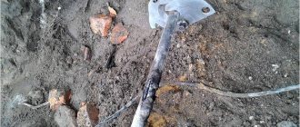
- mechanical damage (most common for cables running in the ground);
- oil leakage from oil-filled cables;
- other types of damage, including multiple violations of insulation integrity or wire breaks along the entire length of the cable.
During the operation of the cable, regardless of external conditions, it ages and wears out. That is why periodic checking for breakdowns is mandatory for all types of high-voltage lines.
Among all these defects, single-phase damage is the most common - in this case, one of the current-carrying wires is shorted to the shielding sheath of the cable. In turn, interfacial faults (in which several cores are melted and welded together (and often with a shielding shell) account for no more than 20% of all damage.
If we consider the reasons why such defects occur, we can highlight the following:
- design errors (for example, underestimated cross-sectional area of the cores);
- factory defects (uneven insulation, burrs on current-carrying conductors, etc.);
- mechanical damage during installation;
- violations during installation of couplings;
- cable damage during operation.
In any case, in order to avoid destruction of the cable during operation and to detect its damage in time, tests are carried out using increased voltage.
Testing of XLPE insulated cable
Cable with XLPE insulation is tested with alternating current voltage. By changing the polarity of the charge, it is possible to compensate and discharge the accumulated charges. When testing with a particularly low frequency voltage, it is possible to obtain the maximum rate of breakdown development and detect problems. To prevent damage to the cable line, the supplied voltage must have the form of a strictly symmetrical sinusoid.
Tests of cable lines, high-voltage tests of cross-linked polyethylene cables and inserts with XLPE insulation are mandatory before putting lines into operation and after completion of repair activities. Testing of a cable made of cross-linked polyethylene 10 kV and other voltages is carried out according to the instructions UP-B-1. Its requirements are presented in the table
Sequence of SCL testing
- Familiarization with design and technical documentation.
- Study of passports of tested electrical installations.
- Implementation of a set of organizational and technical measures required when carrying out work on existing electrical installations.
- Monitoring the serviceability of instrumentation equipment and other devices used for testing, in accordance with the requirements of the Operating Manual for a specific device model.
- Testing of cable power lines up to 10 kV in the scope specified in Chapter. 1.8.37 PUE-7.
Testing the sheath of XLPE cable
The sheath of XLPE-insulated cables is often damaged due to mechanical or corrosive influences. If this defect is not corrected in a timely manner, the main insulation will lose its protective qualities and a breakdown will occur. The sheath of an XLPE cable with a voltage of 10–20 kV is tested with a voltage of 5 V DC for 10 minutes. When a breakdown is detected, a local search for the location of the defect is carried out.
Sheaths of 10–20 kV cables with XLPE insulation must be tested:
- before putting the cable line into operation;
- 2.5 years after the cable line was put into operation and thereafter with an interval of 5 years;
- after repair of the insulating layer;
- during excavations carried out in the security area of the cable line - due to the risk of damage to the protective shells.
For comprehensive testing of cables, testing of 10 kV power cables and their sheaths, a special hardware complex is used. It identifies damaged areas and pinpoints the location of defects with high precision automatically using a step-by-step voltage method.
| type of power cable, kV | less than 1* | 6 | 10 | ||
| paper insulating sheath | |||||
| P | 6 | 36 | 60 | ||
| TO | 2,5 | ||||
| M | — | ||||
| plastic insulating shell | |||||
| P | 3,5 | 36 | 60 | ||
| TO | — | ||||
| M | — | ||||
| rubber insulating shell | |||||
| P | 6 | 12 | 20 | ||
| TO | |||||
| M | 6* | 12* | 20* | ||
Test report for power cable line above 1000V
Below is an example of filling out the test report tables:
In the “General Data” table, in the column number of couplings, I suggest recording not only intermediate couplings, but also end couplings. In this case, even on a cable without intermediate couplings, it is necessary to indicate the number 2 in this column. With this filling, this column remains empty only in the case of testing the power cable, for example on a drum, or before laying and installation.
| Beginning of CL | End of CL | Cable type | Length, m | Number of couplings | Note |
| ZRU, cell 1 | TP-2, T-1 | SBG 3x35 | 250 | 2 | — |
In the table “High Voltage Insulation Test”, in the leakage current column, it is necessary to record the current at the beginning of the test (steady-state) and the current at the end of the test before removing the voltage.
| Name | Cable | Note | ||
| L1–(L2+L3+^) | L2–(L1+L3+^) | L3–(L2+L1+^) | ||
| Usp (kV) | 60 | 60 | 60 | |
| Iut. (µA) | 110/100 | 120/100 | 110/80 | start/end |
| Cont. tests | 5 minutes | 5 minutes | 5 minutes | |
Prices for electrical measuring work "PROFENERGIYA":
| Services | Unit | Cost per unit of measurement, rub. | |
| Electrical installations over 1000 V to 35 kV | |||
| Checking compliance of the installed electrical installation with the requirements of the design documentation | inspection | From 3000 | |
| Checking the presence of a circuit between grounding conductors and grounded elements | dot | From 25 | |
| Testing of fuses, fuse-disconnectors for voltages over 1 kV. | PC. | From 490 | |
| Testing of power cable lines with voltage up to 20 kV. | PC. | From 9500 | |
| Testing of power cable lines with cross-linked polyethylene insulation with voltage up to 35 kV. | Trial | From 8000 | |
| Testing of power transformers, autotransformers, oil reactors and grounding arc arresters with rated voltage up to 35 kV. power up to 63000 kVA | PC. | From 15000 | |
| Testing of switchgear and switchgear. | PC. | From 14900 | |
| Testing of oil, air, vacuum circuit breakers, disconnectors, short circuiters and separators. | PC. | From 1400 | |
| Testing of complete busbars (busbars). | PC. | From 2500 | |
| Testing of busbars and connecting busbars. | PC. | From 2500 | |
| Testing of valve, tubular arresters and surge suppressors. | PC. | From 4000 | |
| Testing of bushings and bushings. | PC. | From 5000 | |
| Testing of suspension and support insulators | PC. | From 6000 | |
| Testing of dry current-limiting reactors. trial | Trial | From 5000 | |
| Inspection of cells (checking and adjusting relay equipment) | Complex | From 15000 | |
| Testing of AC electric motors with rated voltage up to 20 kV. | Complex | From 20000 | |
| Checking switchgear and their connections | Complex | From 10000 | |
| Testing of electrical equipment with increased voltage 1 kV industrial frequency | Measurement | From 500 | |
| Testing of synchronous generators and compensators | Measurement | From 8000 | |
| Testing of measuring current transformers | Trial | From 5000 | |
| Testing of voltage transformers | Trial | From 3500 | |
| Testing of dry current-limiting reactors. | Trial | From 4500 | |
| Capacitor testing. | PC. | From 1800 | |
| Transformer oil testing | Sample (1 liter) | From 8000 | |
| Testing power lines with voltages above 1 kV | Complex | From 20000 | |
| Comprehensive testing | |||
| Carrying out electrical measuring work with the preparation of a technical report from 1000V to 35kV | |||
| Acceptance tests. | Complex of works | From 20000 | |
| Performance tests. | Complex of works | From 20000 | |
| For certification purposes | Complex of works | From 8000 | |
| Engineer visit | Departure | For free | |
| Drawing up single-line diagrams | PC. | From 2000 | |
| Drawing up a grounding device passport | PC. | From 10000 | |
Locations of insulation defects are also determined in stage 2. First, preliminary localization is carried out using the loop method and precision bridge, and then precise identification of defective locations is carried out using the step voltage technique.
To identify locations of damage to the cores themselves, various technologies are used:
- for a 3-core cable – burning;
- for initial localization - non-burning methods;
- for high-precision detection of defects - acoustic method.
Timely testing of high-voltage lines is necessary to increase the reliability of electrical networks and increase the period of their uninterrupted use.
| Carrying out electrical measuring work with the preparation of a technical report from 1000V to 35kV | |||
| Acceptance tests. | Complex of works | From 20000 | |
| Performance tests. | Complex of works | From 20000 | |
| For certification purposes | Complex of works | From 8000 | |
| Engineer visit | Departure | For free | |
| Drawing up single-line diagrams | PC. | From 2000 | |
| Drawing up a grounding device passport | PC. | From 10000 | |
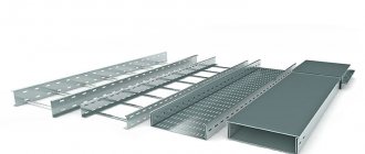
Modern electrical capabilities make it possible to provide energy to any national economic facility. Due to the density of urban infrastructure, as well as the minimum distance between industrial and manufacturing enterprises, power lines are equipped with high voltage power cables. When distributed to consumption points, it is transformed to the required level.
Beginning of work
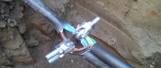
We connect the conductors to each other and to the ground
The test is carried out after applying a higher voltage, but the current must be rectified. It must be applied to all parts of the power cable individually. In this case, everything to which voltage is not applied must be grounded, namely:
- unused cores;
- metal protection;
- shielding surface.
So it is possible to determine whether the insulation between a certain residential area and the surface of the earth is strong, and of course, also in relation to other phases.
Two conductors and a screen are grounded
If the cable is not armored and not shielded, then the voltage is applied between the desired core and other parts that are connected to each other and grounding.
You can simultaneously take all the phases in the cable, no matter how many there are, and test everything at once with an increased voltage, but then the value of the leakage currents must be accurately measured for each wire. If the power cable has only one phase conductor, protected by armor or a shielding surface (made of cross-linked polyethylene), then this voltage must be applied between one of the conductors and the shell, in the latter case this will be metal protection or a shielded coating.
Two conductors and armor are grounded
The power cable is completely de-energized from the equipment connected to it or the buses connected to it; its wires are separated and diverted to the sides by 15 cm.
Why are tests carried out?
During long-term operation, cable lines are inevitably exposed to external influences.
The factors that determine the wear of the CL include:
- sharp amplitude of seasonal temperatures;
- groundwater activity;
- excessive atmospheric activity (ice storm is especially dangerous);
- soil mobility.
In addition, constant overloading of lines has a detrimental effect. As the insulating layer wears out, the CL gradually loses its original performance characteristics.
To prevent external factors from having a destructive effect, it is recommended to systematically test cable lines with high voltage. Proper organization of testing ensures the flawless functioning of networks, as well as minimizing emergency and abnormal situations.
Treatment frequency
Inspection of cable lines is required after construction and installation activities, before putting the facility into operation, and upon completion of modernization and reconstruction. Possible errors during installation are identified and eliminated.
During operation, the equipment is exposed to the negative effects of the external environment (soil displacement, temperature changes, mechanical damage, natural wear and tear of the material). To ensure trouble-free operation of high-voltage lines, preventive tests are carried out:
- for spare networks – every five years;
- for workers - every three years;
- for main and reserve ones supplying especially significant facilities - annually.
Our staff is staffed by qualified engineers who are authorized to carry out such actions and prepare relevant reports.
Who has the right to perform an inspection?
Since this type of work is a task of increased complexity and contains a potential danger to health and even life, employees with permits are allowed to test cables.
For example, when working with a megohmmeter, electrical safety group III is required, and for performers of a full range of work - IV. The organizer (leader) is required to have group V in electrical safety. The fact of admission is recorded in the appropriate certificate. In addition to the group, it reflects information about aptitude tests.
In this case, the minimum work experience in the profile is 3 full months. This refers to direct experience in testing cables that took place during the specified 3 months. Without the practice of high-voltage testing, even an actual three-month presence in the profession is considered insignificant.
Measuring current distribution in single-core cables
On the power cable, currents flowing both in the conductors and in the metal sheaths and armor are measured. Measurements are made using current clamps.
Depending on the sheath material, armor and position of the cable in space, the currents in them can reach 100% relative to the core current and greatly affect the heating of the cables. Simultaneously with measuring currents at loads close to the rated load, the temperature of the outer covers of the cables must be measured, from which the temperature of the core can be calculated. This temperature should be measured at the hottest point of the cable line and should not exceed the permissible temperature for a given measurement location. If the current distribution is uneven by more than 10%, when individual cables limit the throughput of the entire group of cables, measures must be taken to equalize the currents across phases.
Tests: how they are carried out
The first check for serviceability is carried out immediately after laying the cable, even before the official commissioning. Later in everyday functionality this operation is repeated.
Work is not carried out at sub-zero temperatures. Even a slight drop in the mercury column beyond zero is a good reason to cancel tests. The fact is that icy water particles have dielectric properties (some of them are very likely to get into the cable). High voltage tests will be useless or the results obtained will not be reliable.
The test method with increased rectified voltage is that it is applied to each cable core (while the rest are grounded).
Leakage is defined as follows:
- insulation test to earth;
- phase-to-phase insulation testing.
The performance of the CL is recognized if shocks and small discharges are not traced. When completed, the line is discharged.
High-voltage testing of cross-linked polyethylene cable (regulations)
| Periodicity |
Important ! If there are no breakdowns, the cable sheath is inspected for integrity once every 5 years. | |
| First method | Second method | |
| Testing 10 kV XLPE cable | It is carried out using alternating voltage with a frequency of 0.1 Hz. Duration: 30 minutes. If the cable line repair work has just finished, 20 minutes is enough. Important ! An industrial diagnostic VLF installation for XLPE cables is used. Test procedure:
| Checking CL 10 6 kV is performed with alternating voltage (10 or 6 kV, respectively). Voltage is applied between the core and the screen. Duration - 24 hours. Test procedure:
Important ! Timing begins from the moment the voltage rises to the maximum level. |
| Current leaks considered normal | For a 6 kV cable - up to 200 µA. For 10 kV - no more than 500 µA. | |
A licensed engineer conducts 10 kV cable testing with quality assurance. Availability of licenses from Rostekhnadzor and SRO, modern equipment - a guarantee of the accuracy of the results obtained. Based on the test results, our specialists prepare a report.
Determination of the electrical working capacitance of the cores.
Produced for lines 35 kV and above. The measured capacity, reduced to specific values, should not differ from the factory test results by more than 5%.
The capacitance of cable lines is measured using an ammeter-voltmeter method or a bridge circuit.
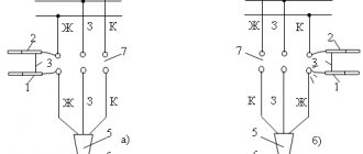
Ammeter-voltmeter method. allows you to accurately determine capacitances with values of C≥0.1 µF, which corresponds to the parameters of the cables. The measurement scheme for this method is shown in Fig. 2.
Based on the results of measuring voltage and current, the capacitance, μF, is calculated using the formula
where: I - capacitive current, A; U is the voltage on the cable, V; f is the frequency of the network voltage, Hz.
Based on the measurement data, the specific capacitance of the cable is determined, μF/km
In the case when measurement by the ammeter-voltmeter method requires special equipment and instruments, it is desirable to use the bridge method.
When measuring with the bridge method, alternating current bridges such as MD-16, P5026, P595, etc. are used. Measurements are made using an inverted circuit (the instructions for the measurement procedure should be followed). When choosing measuring instruments, it should be taken into account that the specific linear capacitance of cables of 35 kV and above is tenths of μF/km, and the limits for measuring capacitance with AC bridges are in the ranges:
bridge P5026 at a voltage of 3-10 kV - 10 ÷ 1 µF, at a voltage less than 100 V - 6.5 10-4 ÷ 5 10 2 µF;
MD-16 bridge at a voltage of 6-10 kV - 0.3 10-4 ÷0.4 µF, at a voltage of 100 V - 0.3 10-3 ÷100 µF;
bridge P595 at a voltage of 3-10 kV –3 10-5 ÷1 µF, at a voltage less than 100 V – 3 10-4 ÷102 µF.
Measuring 6-10 kV cable insulation resistance
First, a visual inspection of the integrity of the shell is carried out and it is cleaned of contaminants. If damage to other network elements (couplings, protective screens) is detected, the check continues only after they have been eliminated. Tests are carried out at air temperatures above zero degrees. The condition is mandatory, since moisture frozen on the coating will distort the real readings (ice is a dielectric).
Resistance measurement is the first stage of the study, which is carried out with a megohmmeter. The device must show at least ten megohms, otherwise you will have to determine the location of cracks and other defects.
A breakdown of the insulation of a high-voltage cable can lead to shutdown or failure of electrical equipment, a fire, and a threat to human health and life. Therefore, it is so important to constantly carry out such measurements.