- home
- Miscellaneous
>
⬎
Battery screwdrivers are very convenient to use and are widely used by both professionals and home craftsmen. The battery is usually the first to fail. Currently, all manufacturers of power tools have switched to lithium batteries and purchasing a new nickel-cadmium battery for an old screwdriver is becoming more and more problematic, and the prices for these batteries are much higher than for lithium ones.
Of course, it is possible to purchase batteries on various services that sell Chinese goods. But it takes time for the package with the “cans” to arrive, and again, these are certain costs. There is an alternative to buying batteries/cans - connect the screwdriver to the mains power supply and forget about quickly draining the batteries. Powerful power supply on Aliexpress. There are many inconveniences due to the power cord, but you always have to sacrifice something.
How much current does a screwdriver consume?
Before choosing a suitable power supply, you need to understand what current consumption you need to count on. Unfortunately, cordless screwdriver manufacturers do not indicate the current consumed by the motor. The capacity of the battery itself in ampere-hours, which is necessarily indicated on the battery, does not allow us to understand how much current the screwdriver consumes in operating mode
. The maximum that the manufacturer can indicate is the power in watts, but this is very rare, usually the power is indicated directly in torque.
If the power in watts is still indicated, we can have an idea of the current consumption and select an appropriate power supply with a small current/power margin. To calculate the current, it is enough to divide the power in watts by the operating voltage of the screwdriver, in this case it is 12 volts. So, if the manufacturer indicated a power of, for example, 200 watts - 200:12 = 16.6 A - this is the current consumed by the screwdriver in operating mode.
However, the indicated power is very rare and there is no universal figure that characterizes all 12-volt screwdrivers. You need to understand that when the motor shaft is fully braked, the currents can significantly exceed the rated ones and calculating this value is not very easy. At the same time, an analysis of various forums and our own experience has shown that a current of 10 A is often sufficient to operate a screwdriver; this is enough to perform many screwing and drilling functions. It is known that current surges during complete braking of the shaft can exceed 30 A.
Well, what conclusion can be drawn from all this? A 12 V power supply providing 10 A current is suitable for a screwdriver; if it is possible to use a 20-30 A unit, this is even better. These are average figures that apply to most screwdrivers.
Capacitance or voltage
The elementary sources from which the battery for a screwdriver is assembled have different voltages, so a Ca-Ni battery has 3.2 V, a Li-ion battery has 3.6 V. If we connect three batteries in series, we get 12, 6V and 13.2V. A series connection is a connection in which the positive terminal is connected to the negative terminal of the next battery, and the positive terminal to the negative terminal of the next battery, forming a continuous chain. With this connection, the battery voltage is added. If you connect the batteries plus to plus, and the negative terminal to minus, then the voltage remains the original, but the capacity will double. Thus, if it is necessary to increase the voltage, we assemble a serial (serial) connection, if the capacitance is a parallel connection (parallel).
power unit
We will not consider purchasing any units or transformers, and if we do buy it, it will be a new battery! We will consider using what we have on hand. I’ll say right away that the charger from the same screwdriver is only suitable for drilling overripe bananas, its power is too low.
Ideally, a step-down, powerful 12 V transformer, for example from a computer uninterruptible power supply, would be suitable. The power of such a transformer is usually 350-500 watts. But I didn’t have such a transformer, but I had a lot of computer power supplies. I am sure that if someone has various electronic junk, ATX computers are definitely lying around in it.
This is one of the first representatives of computer ATX power supplies.
The computer ATX unit is quite suitable for a screwdriver; the load capacity on the +12 volt bus allows you to remove currents of 10-20 amperes. I would like to dispel a small myth - it will not be possible to stuff the unit into the battery housing of a screwdriver, the ATX board is too large. You will have to make a separate case for the block or leave it in its original metal case. The disadvantage of the original case is sensitivity to dust, and even the smallest repair requires a lot of dust.
A rather weak unit, the load on the +12V bus is only 10 A. If possible, it is better to choose units with a more powerful twelve-volt bus.
Benefits of Upgrading
Transforming a cordless tool into a device that operates continuously from the mains has the following advantages:
- The need to recharge the device is completely eliminated, reducing downtime during long-term work.
- Providing a constant current strength, due to which the torque receives a constant value.
- The screwdriver can not be used for a long time, its technical parameters do not deteriorate.
The only drawback to improving the device is the presence of an electrical outlet near the work being performed. This problem is easily solved by connecting an extension cord.
Mock Tests
Before starting to build a working structure, you should test everything on the knees, make sure that the screwdriver is operating stable under load and that there is no severe overheating in the power supply.
We take the computer power supply and check it: plug it into the network, find green in the output bundle of wires (they say it can be a different color, but I always came across green ones) and connect it with a jumper to any of the black ones (all black wires at the output are the common output, in our case it is a minus). The unit should turn on and a voltage of 12 volts will appear between the black and yellow wires. You can check this with a multimeter or by connecting any computer cooler to the named terminals.
If everything is in order and the unit produces about 12 volts on the yellow (+) and black (-) terminals, continue. If there is no voltage at the output, we look for another unit or repair this one; this separate topic will be described separately.
We cut off the plug from the output of the block and take 3-4 yellow and black wires coming from the block and connect them in parallel. When cutting off the plug, do not forget about the green starting conductor, it must be shorted to black. We received a 12 V source with a decent current load capacity of 10-20 A, the currents depend on the model and power of the unit.
Now we need to connect our 12 V to the terminals of the screwdriver without a battery; we look at the polarity of the connection using the battery. Well, we check the screwdriver - at idle speed, then slowing down by hand. At this stage, I encountered a problem: when I press the button fully, the screwdriver works, but when I slowly, smoothly press the screwdriver button, the power supply goes into protection. To reset the protection, you must disconnect the unit from the network and turn it on again. This won’t work at all, we need to somehow correct this instability.
I pulled the block board out of the case and additionally hooked up a multimeter to constantly monitor the voltage
In my opinion, this phenomenon may occur due to the fact that the power supply and the screwdriver button are controlled by PWM controllers; due to interference along the power wires, the controllers somehow interfere with each other. We are trying to solve this problem using an improvised LC filter.
I assembled the filter in 5 minutes from what was at hand: 3 electrolytic capacitors of 1000 uF at 16 volts, a non-polar capacitor of less than 1 uF and wound 20 turns of copper wire with a diameter of 2 mm on a ferrite ring from another unit. Here is his diagram:
And this is what he looks like. This is a purely trial version, in the future this design will be transferred to the battery housing of the screwdriver and will be made more accurately.
We check the entire structure: the block does not go into protection in any position of the button, great! Now you can try tightening several screws - all in a bunch. It seems that the screwdriver will be able to tighten larger screws.
Well, now you need to remove all the snot and piles of wires, remove the “dead cans” from the battery case, replace them with an LC filter, and test the screwdriver in more realistic conditions.
Easy tool restoration
The main advantage of a cordless screwdriver is its mobility. These tools use a lithium-ion battery, which is protected from overload and complete discharge. In addition, there is protection against overcharging in the form of a separate circuit built into the element itself. The main power source (primary) is 220 V, and the battery is also recharged.
Depending on the model of the screwdriver, the battery receives a charging voltage from 14 V to 21 V. The battery output produces a supply voltage from 12 to 18 V. This type of battery lasts a long time, but if the tool is not used for a long time, the built-in discharge protection will not help battery cells: discharge occurs constantly.
To increase service life, it is necessary to constantly discharge and charge the battery. If for some reason it was not possible to “keep track” of the tool, a specific battery element often fails. There are basic ways to solve this problem:
- Replace the battery with a new one.
- Buy a new tool.
- Convert a mains-powered screwdriver.
When replacing the battery, please note that a new one is quite difficult to find. The tools are made in such a way that it is difficult to find spare parts for them. It is not profitable for a company to produce its product with high repairability, since it needs income from the purchase of products. You can only find a new battery at dealers. In addition, another option is possible: disassemble the battery and replace the faulty battery.
When purchasing a new tool, the user tends to buy a model of a higher quality, forgetting about the rules for using lithium-ion batteries. Basic rules that will help preserve the service life of the tool for a long time:
- When purchasing in winter, it is strictly forbidden to “launch” the tool immediately. You need to wait about an hour until it “warms up” to room temperature.
- Place the battery on charge.
- Perform the battery charging and discharging cycle about 3 times.
If none of the options for solving the problem are suitable, you need to start converting the screwdriver to a network one with your own hands. It's easy to do. There are many simple and complex ways. Changing the tool model has several positive aspects:
- There is no need to recharge the battery.
- The load on the mechanical part is reduced.
- Lots of power supply options.
- Increasing the quality characteristics of the product.
In addition, it is possible to maintain mobility by converting the charger into a block version for charging almost any battery.
Assembly of the working structure
For ease of use and connection, I brought the cord from the power supply into the battery case. I took a 3.5 meter long cord that was available. I removed all the battery cells from the battery and installed an LC filter. Now, if I somehow get a working battery, I can always put it on a screwdriver and put the power supply away as a reserve. I didn’t throw the batteries out of the battery, I have an idea where to use them, but that’s a topic for another review.
Since the cord connecting the unit to the screwdriver has a certain resistance and inductance, you can try to close the terminals of the L1 coil with a jumper. In theory, this could increase power by a tiny amount.
The screwdriver feels great with a cord, but to be honest, it seemed a little weak to me when braking by hand. But trial tightening of the self-tapping screws dispelled my doubts: self-tapping screws 35 mm long can easily be screwed into 20 mm plywood. This means that a screwdriver will cover most repair needs.
I cut off all the output wires from the block, leaving the green starting wire; I soldered its end to the common conductor of the board, where all the black ones are soldered. It's best to carefully desolder all the wires, but my soldering iron was too weak for this and had to be cut. I soldered two short, hard copper wires to the common contact and +12 (where the yellow ones are soldered) and connected them through the terminal block to the cord to the Shura.
This is where we will finish this review; we have achieved what we wanted - the screwdriver works perfectly with a computer power supply. In the future, I plan to make a high-quality plywood case without cracks for the power supply board - tests have shown that the heatsinks on the board do not heat up at all and you don’t have to worry about overheating of the elements in a closed case.
Operating rules
If the screwdriver has relatively little power, you need to install a homemade power supply in the battery compartment. When assembled separately, all power supplies must be provided with cooling using a fan or motor with an impeller. The case should not be sealed, as overheating will occur (hot air will have nowhere to escape). When the power supply is ready, you need to check the screwdriver in combination with the power source. Basic requirements for using the tool to extend its service life:
- Working time: 30-40 minutes, after which you need to pause until it cools completely.
- Avoid working at high altitudes.
- Monitor the condition of the power cable, battery (if used), temperature of the tool and homemade power supply.
Thus, if the battery of an 18 V screwdriver fails, you can avoid unnecessary costs. If mobility is important, then it makes sense to purchase a new battery or the tool itself. There are many options proposed by radio amateurs to extend its service life. It is necessary to select the optimal one for the specific application of the device.
Originally posted 2018-04-18 12:15:52.
Few additions
To compensate for losses in the cord connecting the screwdriver to the power supply, it is useful to increase the voltage by 2-3 volts. But this is provided that you know the circuit design of ATX computers and know what to do.
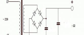
If it is possible to use a powerful transformer, then its output, secondary winding should have an alternating voltage of 12 V. If the voltage is different, it is recommended to adjust the secondary winding by unwinding (if the voltage is more than 12 V) or rewinding (if less than 12 V) several turns. It is worth noting that when rectifying and filtering the 12 V AC voltage, it turns out to be about 14.4 V without load. So don’t let this confuse you, this is the EMF voltage and it is natural that it is higher than the nominal one.
In addition to the transformer, a rectifier is assembled; the diodes should easily hold 30 A. It is more expedient to place the capacitor filter in the battery case, as in the ATX version.
Makita
Makita spare parts can also be purchased separately. The manufacturer offers a universal charger for all existing types of batteries. The system will automatically select the required voltage.
On a special control panel you can see the progress of the process. If the battery is not working, this will also be indicated.
Prices for Makita spare parts start at 2,000 rubles (for household models). Chargers and batteries for professional tools will cost much more.
Tips for use
Experts in changing screwdrivers, who easily cope with the assigned task, advise beginners to follow certain rules:
- A corded screwdriver can operate for several hours at a time, so give it five-minute breaks to protect it from overload.
- The wire should be attached to the elbow area to prevent interference during operation.
- The power supply must be systematically cleaned of dust and dirt.
- The battery (new) is provided with grounding.
- It is not recommended to use a large number of extension cords.
- Do not use a screwdriver when working at height (from two meters and above).
Following these tips will help keep the tool in working condition and extend its life.
Connecting the screwdriver to the charger
Sequencing:
- Solder or attach two wires with alligator clips to the terminals of the charger.
- Disassemble the old battery and remove the dead cells from it.
- Drill a hole in the battery case for the cable, thread the cable into the hole. It is advisable to seal the connection with electrical tape or heat-shrink tubing to prevent the wire from tearing out of the housing.
- Elements removed from the battery will disrupt the weight distribution of the screwdriver - your hand will get tired. To restore balance, a weight should be placed in the body - it can be dense wood or a piece of rubber.
- Solder the cable to the terminals of the former battery, connected to the screwdriver.
- Assemble the battery housing.
- All that remains is to test the updated tool in action.
Installation of a finished power supply in the housing of an old battery
Procedure:
- Disassemble the old battery and remove the non-functioning elements from it.
- Install the power supply into the battery case. Connect the high voltage terminals and low voltage terminals.
- Assemble and close the battery case.
- Install the battery into the screwdriver.
- Plug the power supply into the outlet and check the updated network tool in operation.
Homemade power supply
Step-by-step instruction:
- Disassemble the old battery case and remove the dead batteries from it.
- Install the elements of the electrical circuit of the power supply onto the circuit board, solder the contacts.
- Install the assembled board into the case. Use a tester to check the presence of voltage at the output.
- Connect the low voltage wires to the terminals of the old battery. Assemble the body.
- Connect the screwdriver to the electrical network and check its operation.
Connecting to an external power supply
What to do:
- Disassemble the screwdriver and find the motor power wires inside. Install the connector for the power supply into the case and solder the wires to the connector. Secure the wires with hot glue.
- Choose a suitable power supply, for example, from a laptop. Find an adapter for the low voltage connector.
- Connect the screwdriver to the new power supply and check its operation.
Connecting to a power supply from a computer
Instructions:
- Find or buy a computer power supply with a power of at least 300 W.
- Disassemble the screwdriver body. Find the motor power wires inside. Solder the connectors for the computer power supply to the wires.
- Remove the connectors for connecting the computer power supply from the case.
- Connect the screwdriver to the new power supply.
- Connect the power supply to the network and check the operation of the device.
Homemade charging devices
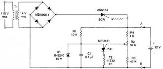
It’s quite simple to make a charger for a 12-volt screwdriver yourself, by analogy with the one used in the Interskol charger. To do this, you will need to take advantage of the ability of the thermal relay to break the contact when a certain temperature is reached.
In the circuit, R1 and VD2 represent a sensor for the flow of charge current, R1 is designed to protect the diode VD2. When voltage is applied, transistor VT1 opens, current passes through it and LED LH1 begins to glow. The voltage drops across the chain R1, D1 and is applied to the battery. The charging current passes through the thermal relay. As soon as the temperature of the battery to which the thermal relay is connected exceeds the permissible value, it is triggered. The relay contacts switch and the charging current begins to flow through resistance R4, the LED LH2 lights up, indicating the end of the charge.
Circuit with two transistors
Another simple device can be made using available elements. This circuit operates on two transistors KT829 and KT361.
The amount of charge current is controlled by the KT361 transistor to the collector to which the LED is connected. This transistor also controls the state of the KT829 component. As soon as the battery capacity begins to increase, the charging current decreases and the LED gradually goes out accordingly. Resistance R1 sets the maximum current.
The moment the battery is fully charged is determined by the required voltage on it. The required value is set with a 10 kOhm variable resistor. To check it, you will need to place a voltmeter on the battery connection terminals, without connecting the battery itself. Any rectifier unit designed for a current of at least one ampere is used as a constant voltage source.
Using a custom chip
Manufacturers of screwdrivers are trying to reduce prices for their products, often this is achieved by simplifying the charger circuit. But such actions lead to rapid failure of the battery itself. By using a universal chip designed specifically for the MAXIM MAX713 charger, you can achieve good charging performance. This is what the charger circuit for an 18-volt screwdriver looks like:
The MAX713 chip allows you to charge nickel-cadmium and nickel-metal hydride batteries in fast charge mode, with a current of up to 4 C. It can monitor battery parameters and, if necessary, reduce the current automatically. Once charging is complete, the IC-based circuit draws virtually no power from the battery. It can interrupt its operation due to time or when the temperature sensor is triggered.
HL1 is used to indicate power, and HL2 is used to display fast charge. The setup of the circuit is as follows. To begin with, the charging current is selected, usually its value is equal to 0.5 C, where C is the battery capacity in ampere hours. The PGM1 pin is connected to the positive supply voltage (+U). The power of the output transistor is calculated using the formula P=(Uin - Ubat)*Icharge, where:
- Uin – highest voltage at the input;
- Ubat – battery voltage;
- Icharge – charging current.
Resistance R1 and R6 is calculated using the formulas: R1=(Uin-5)/5, R6=0.25/Icharge. The choice of time after which the charging current turns off is determined by connecting the PGM2 and PGM3 contacts to different terminals. So, for 22 minutes PGM2 is left unconnected, and PGM3 is connected to +U, for 90 minutes PGM3 is switched to the 16th leg of the REF chip. When it is necessary to increase the charging time to 180 minutes, PGM3 is short-circuited with the 12th leg of the MAX713. The longest time of 264 minutes is achieved by connecting PGM2 to the second leg, and PGM3 to the 12th leg of the microcircuit.
Safety precautions
The work area when altering the device must be sufficiently illuminated. The most effective are fluorescent or LED lamps combined with daylight falling from the window on the left. Glare or direct light entering the eyes should be avoided.
To avoid electric shock, it is better to avoid contact with grounded objects, such as radiators and gas stoves. The work table, chair, floor should not have conductive surfaces.
When working with radio components, you need to check that there is no voltage on them; an indicator screwdriver is suitable for this. After disconnecting from the power supply, you need to remove the charge from the circuit capacitors. Remove the charge, for example, with a voltmeter.
Connect the equipment only after checking the strength of the connections. It is better to check not only visually, but also mechanically.
The workplace must be ventilated or equipped with an exhaust hood.
- https://amperof.ru/elektropribory/peredelka-shurupoverta-pitanie-ot-seti.html
- https://metmastanki.ru/peredelat-akkumulyatornyy-shurupovert-v-setevoy
- https://100uslug.com/neskolko-sposobov-peredelat-akkumulyatornyj-shurupovyort-v-setevoj/
- https://kraska.guru/instrumenty/elektro/kak-perevesti-akkumulyatornyj-shurupovert-na-pitanie-ot-seti.html
- https://tehnika.expert/dlya-remonta/shurupovert/peredelka-akkumuljatornogo-na-setevoj.html
- https://tool-and-tools.ru/dreli-i-shurupoverty/peredelyvaem-shurupovert-na-setevoj.html
- https://100uslug.com/kak-sdelat-shurupovyort-napryamuyu-ot-zaryadki/
- https://CleverDIY.ru/kak-sdelat-shurupovert-ot-seti-svoimi-rukami
- https://DomZastroika.ru/instrumenty/kak-peredelat-akkumuljatornyj-shurupovert.html
- https://intehstroy-spb.ru/elektroinstrument/peredelka-shurupoverta-na-pitanie-ot-seti.html
- https://my-class.ru/kak-podklyuchit-shurupovert-napryamuyu-k-yego-zaryadnomu-ustroystvu/
- https://morflot.su/podkljuchenie-shurupoverta-k-zarjadnomu-ustrojstvu/
- https://m-strana.ru/articles/peredelka-shurupoverta-na-pitanie-ot-seti/
- https://MegaBattery.ru/articles/info/zaryadnye-ustrojstva-shurupovertov/mozhno-li-podklyuchit-shurupovert-napryamuyu-k-zaryadke/