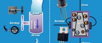
The operating principle of IGBT transistors is based on the use of a low-power n-channel MOS transistor to control a powerful bipolar transistor. Thus, it was possible to combine the advantages of a bipolar and field-effect transistor. Low control power, high input resistance, high level of breakdown voltage, low on-state resistance - allow IGBTs to be used in circuits with high voltages and high currents.
Insulated gate bipolar transistors (IGBTs or IGBTs) are useful for high-current, high-voltage switching circuits. Welding machines, uninterruptible power supplies, electric motor drives, powerful voltage converters - this is the scope of application of such elements.
IGBT pin names: gate, emitter, collector.
Insulated gate bipolar transistors are capable of switching currents of thousands of amperes; the emitter-collector voltage can reach several kilovolts. But the operating frequency of these transistors is much lower than the frequency of field-effect transistors.
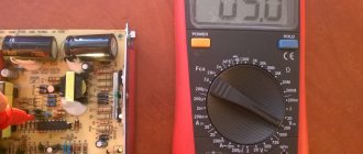
How to test an IGBT transistor with a multimeter
IGBT FGH40N60SFD is being tested. IGBTs are often short-circuited; such faulty transistors can be easily identified using a multimeter. Before checking the IGBT transistor with a multimeter, you need to refer to the reference data and find out the purpose of its terminals.
Then do the following:
1. Switch the multimeter to the “dialer” mode. Take a measurement between the gate and emitter to identify a possible short.
2. Take a measurement between the gate and the collector to identify a possible short circuit.
- IGBT transistors. Device and operation. Parameters and Application
3. Briefly short-circuit the emitter and gate with tweezers or a jumper. After this, the transistor will be guaranteed to be closed.
4. Connect the “V/Ω” multimeter probe to the emitter, the “COM” probe to the collector. The multimeter should show the voltage drop across the internal diode.
5. Connect the “V/Ω” multimeter probe to the collector, the “COM” probe to the emitter. The multimeter should show no short circuit or leakage.
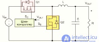
For a more reliable test of the IGBT transistor, you can assemble the following circuit:
When the contacts of the button are closed, the light should light up, and when opened, it should go out.
This video shows how to test IGBT with a multimeter:
Published 11/05/2016