Date: 04/26/2016 //
Often, when repairing or converting an ATX power supply into a car charger, a diagram of this unit is needed. Taking into account the fact that at the moment there are a huge number of block models, we decided to collect a small selection from the network, where typical circuits of ATX computer power supplies will be posted. At this stage, the selection is far from complete and will be constantly updated. If you have diagrams of ATX computer power supplies that are not included in this article and want to share, we will always be happy to add new and interesting materials.
DIY crafts for car enthusiasts
Hello everyone, you have been asking me for a long time to show you how to convert a computer power supply into a charger for a car battery or into a laboratory power supply.
Well, arm yourself with a soldering iron because this day has come, but before we begin, I will note that during the remodeling we need to be extremely careful, since we will be dealing with high voltage.
During setup work, be sure to make sure that the power supply is disconnected from the network; it would also be a good idea to discharge the capacious electrolytes on the power supply board with a light bulb, or after disconnecting, wait a few minutes until the resistors shunting them discharge the capacitance.
The circuit according to which we will remake is quite popular, it is better known as the “scheme from the Italian”, it is relevant for “at” format power supplies based on TL494. Modern power supplies are built on a variety of PWM chips; the most common are power supplies based on the TL490 PWM controller or its analogue KA7500 and the LM339 comparator.
Previously, I have never talked about the process of remaking power supplies, because I believe that it is easier to assemble a new power supply with your own hands than to remake a computer one.
Although there are a lot of archives on the Internet on this topic, they all tell us about remaking specific power supplies; there are no universal methods and there cannot be.
I had to work hard to get the power supply to work as it should, the Italian’s circuit is working (available in the archive at the end of the article), but in order to use it for power supplies based on TL494 and the LM339 comparator, you will have to throw out half of the circuit, and very carefully, so that accidentally Don’t throw away what you need for work.
Therefore, it was decided to make an extremely accessible guide to remaking power supplies; everything will be very clear in pictures and in the smallest detail.
First you need to find a power supply . Blocks built on one TL494 or more modern ones using an LM339 comparator and a TL494 PWM controller are suitable.
First, we connect the green wire with any of the black ones,
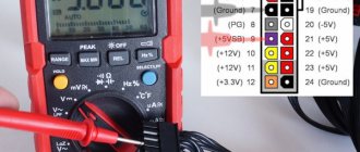
By doing this, by starting the power supply, the fan will start spinning, which indicates that the unit is working, but you shouldn’t be lazy; it’s better to check the voltage at the output of the power supply with a multimeter.
As we know, we have 3.3 volts, 5 volts and 12 volts, if everything is fine, we open the case, take out the board and solder all the wires, leaving only a couple of black, a couple of yellow and a green wire.
They are needed for tests and will be replaced or removed later.
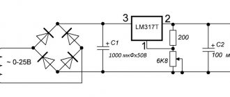
Next , you can also throw out the diode assemblies on the 5 and 3.3 volt lines,
and replace the capacitor on the 12 volt bus with 25,
or better yet, 35 or 50 volt, capacity from 1000 to 2.2 thousand microfarads.
It is very, very desirable to use capacitors with low internal resistance.
Now let’s get serious, look at the TL494 microcircuit (in my case it’s an analogue of the K7500), solder off everything that goes to the first pin of the microcircuit, these are usually several resistors.
Next we look at pins 13, 14 and 15 of the same microcircuit, most likely they will all be shorted to each other, you need to disconnect pin 15 from the other two,
or rather from the 13th and 14th. I personally cut the path,
Thus, conclusions 1 and 15 are already hanging in the air,
go ahead.
We carry out the same operation with pin 16, freeing it from the rest of the harness. Next, take any resistor with a resistance of 2.2 kilo-ohms,
we stretch this resistor from the ground of the power supply, (that is, from the black wire), to the first pin of the microcircuit.
The next thing is to find a 20 kOhm variable resistor and connect it as shown in the photo.
In theory, we have the voltage regulation ready, but we don’t need to check anything yet.
Next, we find a pair of resistors with a resistance of 0.1 ohm, the power of each resistor is 5 watts,
we connect them in parallel and connect one pin to the power ground, the other end of the resistor is connected to pin 16 of the TL494 chip, we will use this resistor as a current sensor.
You think that’s it))) , no... only half the job is done, then you need to download the archive, which is located at the end of the article, there is a printed circuit board in the “sprint layout” program, which I made especially for you and signed in detail.
All points on this board must be connected to the corresponding points indicated on the diagram,
that's it guys now.
You can be happy and move on to the tests, I did everything on a prototype, since I had to experiment.
Now we need to cultivate this whole thing. It is advisable to take the wires that come from the homemade board shielded and as short as possible; it is advisable and even obligatory to fill the places where they connect with resin or hot-melt adhesive.
A broken wire can cause the entire structure to fail.
Now we connect the green wire with the black one, but before that, be sure to take a safety lamp of 40, 60 watts and connect the power supply to the network only through this lamp, otherwise fireworks are possible if there are jambs.
We turn on the power source, first adjust the voltage, make sure that everything is fine and smoothly regulated in the range from one and a half to more than 15 volts, more is possible, but this power supply will be used as a charger for car batteries, and there 15 volts will be enough.
We drive the power supply for several minutes, even with a small load, if everything is fine, remove the safety lamp and connect a more serious load to the output of the power supply, in my case a 60-watt halogen.
Enter your email and receive emails with new crafts.
The multimeter shows the value of the current in the circuit and, as you can see, the current is also perfectly regulated; by the way, you can read more than 10 amperes.
All that remains is to connect a more or less normal voltammeter, for example a Chinese, digital one, for a couple of bucks and good luck, connect as follows.
You can modify this power supply with reverse polarity protection, but that’s another story... Thank you all for your attention.
Archive for the article;
Author; AKA Kasyan
Popular;
- A simple laboratory power supply made from an old computer power supply.
- Charger from power supply from computer
- Charger from a computer power supply
- Charger made from PSU LED strips.
- How to charge a car battery from a laptop power supply, diagram
- Charger for a car from a power supply from an LED strip
- Power supply from an economy lamp
- Charger from economy lamp
Submit Comment
The current stabilization coefficient turned out to be low, plus the voltage drop on the ground wires additionally introduced an error. The placement of power transistors is shown. If a faulty transistor is found, then before soldering a new one, it is necessary to test its entire wiring, consisting of diodes, low-resistance resistances and electrolytic capacitors. Diagram of the new control unit The amplifier in the current control circuit is assembled according to a similar differential circuit for switching on op-amp DA1. Constant airflow is required!
Monitor the heating of the power elements. In principle, the total current consumption of these elements is not high - the standby power supply will handle it just fine.
I set this threshold “by eye” when the radiator with the diode assembly burned my finger..
The design of the front panel has remained virtually unchanged - it has proven itself well from an ergonomic point of view.
For example, at a voltage of 14 V, the unit can supply a current of 16 A to the load, which is very tempting!
The power supply turned out to be so powerful and reliable that it allows: 3 years.
First of all, this is due to the negative feedback chains of the OOS between the pins. In the first option, I abandoned the use of a differential amplifier in the current control loop in order to reduce the number of wires. Converting an ATX sparkman 300 into an adjustable one
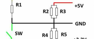
Where is 12 volts and where is 5? Understanding color coding
How can you find out which wires produce which voltages? Where, for example, is 12 volts on the computer power supply? You don't need a tester for this, since all the wires coming out of the computer power supply have a strictly defined, generally accepted color. Therefore, instead of a tester, we arm ourselves with the sign below.
Colors and assignment of ATX power supply wires
| Color | Purpose | Note |
| black | GND | wire common minus |
| red | +5 V | main power bus |
| yellow | +12 V | main power bus |
| blue | -12 V | main power bus (may be missing) |
| orange | +3.3 V | main power bus |
| white | -5 V | main power bus |
| violet | +5 VSB | standby food |
| grey | Power good | nutrition is normal |
| green | Power on | command to start power supply |
The plate does not require any special explanation. We got acquainted with the green wire (Power on) in the previous section - the motherboard sends a low-level signal to it (short to common) to turn on the power supply. The blue wire may be missing in new power supply models, since motherboard manufacturers have abandoned the RS-232C interface (COM port), which requires -12 V.
The purple wire (+5 VSB) is just the standby +5 V that powers the standby nodes of the motherboard. Via the gray wire (Power good), the power supply reports that all voltages are normal and the computer can be turned on. If any of the voltages during operation goes beyond the permissible limits or disappears, the signal is removed. Moreover, this happens before the storage capacitors of the power supply have time to discharge, giving the processor time to take emergency measures to stop the system in an emergency. The remaining wires are power wires for the motherboard and peripheral devices - disk drives, external video cards, etc.
Utilities and reference books.
cables.zip - Cable layout - Directory in .chm format. The author of this file is Pavel Andreevich Kucheryavenko. Most of the source documents were taken from the website pinouts.ru - brief descriptions and pinouts of more than 1000 connectors, cables, adapters. Descriptions of buses, slots, interfaces. Not only computer equipment, but also cell phones, GPS receivers, audio, photo and video equipment, game consoles and other equipment.
Capacitor 1.0 - The program is designed to determine the capacitance of a capacitor by color marking (12 types of capacitors).
Transistors.rar — Database on transistors in Access format.
So, ATX has risen.
The frequency of the internal oscillator is determined by the formula:
Pin 14 is the output of the internal +5 volt reference voltage.
Pins 1,2,15 and 16 are the inputs of 2 built-in comparators, which the user can use at his discretion, i.e. control the width of the PWM output pulses. Both comparators are exactly the same, with the only difference being that the comparator with pins 15-16 operates with a “delay” of 80 mV. In the ATXs I received, this comparator was not used, pin 16 is grounded, and pin 15 is connected to Uref, i.e. 14 output.
Pin 13 is intended for switching the TL-494 into control mode for flyback single-ended converters. In this case, the “dead time” can be increased to 96%. In our “push-pull” case, this pin is also connected to Uref.
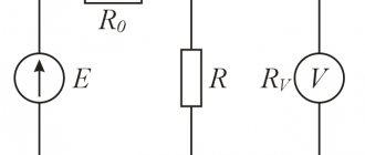
We will use the comparator on pins 1-2 to set the output voltage; for this, we apply part of Uref to pin 2, which is done in most AT and ATX. Typically this voltage is approximately 2.5 volts, i.e. with Uref (+5Volt) through a resistive divider.
The RC chain from pin 2 to pin 3 (FB or OS) is designed to limit the PWM speed while stabilizing the voltage and is available in all AT-ATX circuits. It also cannot be cut out.
I am drawing a simplified output voltage control circuit.