Home > Antennas > Power supply for antenna
The vast majority of antennas for receiving television programs include a signal amplifier. Like any electronic device, it requires a power supply. The main feature is the use of an antenna cable to simultaneously transmit the useful signal and supply voltage. This principle of organizing power supply for an antenna amplifier has long been accepted as a de facto standard by most manufacturers of antennas and amplifiers for them. This is due to the fact that the distance from the amplifier to the power source is large, but no additional cable to the power supply is required.
Antenna with amplifier
Amplifier purpose
Reliable reception of programs for viewing channels on terrestrial television using a conventional antenna is only possible at a short distance from the transmitting center. In all other cases, the active antenna is supplemented with a reception amplifier. As an example, we can cite Polish antennas, which have become very widespread, and Delta-type antennas.
Polish antenna
Antenna Delta
The main function of TV antenna amplifier:
- increasing the level of the useful signal to acceptable values;
- reduction of interference level.
These qualities are listed because the quality of reception is affected not only by the magnitude of the useful signal, but also by its relationship to the level of interference. Based on this consideration, the antenna amplifier is located in close proximity to the antenna, often entering directly into its structure.
The power supply voltage for the antenna amplifier is supplied through the antenna cable. To isolate the useful signal, an antenna, either Delta or any other, is connected to the TV via an adapter. Some TV or tuner models have an antenna socket that already contains voltage. Thus, the need for a power supply and adapter is eliminated, although this does not exclude the possibility of using them. To do this, there must be an item in the TV settings menu that allows you to turn off the antenna power through the antenna input.
Important! The simultaneous supply of power from the antenna socket and the external power supply is not allowed, as this may lead to failure of one or more devices. At best, the quality of reception will suffer.
Signal amplification methods
TV antenna signal amplification is achieved in 5 ways:
- Use a higher quality TV antenna than the one you have. Depending on the design, a few decibels of gain can be gained here. Check if your antenna is selected correctly.
- Precise orientation. Almost all devices operating in the UHF range have a clearly oriented diagram and most efficiently receive a signal from one direction. Even a rotation of 5–10 degrees can give a serious increase in signal strength.
- Replace cable. If the distance between the antenna and the television receiver is too large, the lion's share of the received signal power is lost due to the resistance of the conductor. This can be avoided by using a feeder with reduced resistance (for example, with a central core made of pure copper rather than copper-plated steel).
- Move the TV closer to the antenna. The cable becomes shorter: in some cases, even 2–3 meters can be decisive. Reducing the feeder length allows you to avoid unnecessary signal power losses.
- Use an antenna amplifier.
Power supply parameters
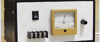
DIY laboratory power supply
The antenna amplifier requires a power supply with the following parameters:
- constant supply voltage from 9 to 12 volts;
- current value is not more than 100 mA.
As a result, the power of a TV power supply is a few watts, so it can have very small dimensions.
Amplifier power supply with adapter
Check the result using a multimeter
Once the circuit has been designed and connected, it makes sense to test it and check the characteristics of the resulting design. To do this, you need to have a tester - a multimeter or any other similar device.
Check the following settings:
- The characteristic impedance of the cable should not exceed 75 Ohms.
- The difference between the braid of the coaxial cable and the central core should be several tens of ohms. If the device shows “0”, it means there is a break or short circuit.
- When connecting the central core and braid, the device should show infinity, that is, the maximum of the scale. But if both the braid and the core are disconnected from the antenna and shorted to each other, the result should be zero.
If all 3 tests are passed, then the amplifier is connected correctly.
Power supply device
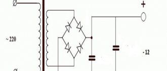
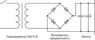
In the vast majority of cases, the power supply for a television antenna consists of a step-down transformer with a bridge rectifier, a filter capacitor and an integrated voltage regulator.
Power supply diagram
The output voltage of the transformer is about 12-18 V, preferably closer to the maximum value. Why this is so will be discussed below. An integrated circuit of type 7812 is used as a stabilizer. It has become very widespread due to its successful parameters and is available with different permissible power. In the power supply under consideration, you can use a microcircuit with minimal power (a more powerful one is quite acceptable, the criterion here is its dimensions). The domestic analogue of 7805 is K142EN8B (short name - KR EN8B). For normal operation of the circuit, it is necessary that the voltage at its input exceeds the output by at least two volts, and since after rectification and smoothing with a capacitor, the alternating voltage increases by about 1.4 times, the minimum voltage at the transformer output is about 10 V. The above limit is 12 V was selected taking into account a possible decrease in the network voltage.
The capacitance of the filter capacitor must ensure smoothing of voltage ripples. In this case, 220 uF is quite enough. The operating voltage of the capacitor should be several times higher than the rectified voltage, so it is better to take a capacitor rated at 35 V or higher. The LED serves to indicate the operation of the unit.
Very often, an antenna can receive both signals from a distant television center and from a nearby one. In this case, it is possible that the antenna amplifier begins to self-excite, that is, generate its own oscillations. Broadband antennas, which also include the Delta antenna, have a similar disadvantage. The quality of reception is greatly deteriorated. To get out of this situation, reduce the gain of the amplifier. This can be done by reducing the supply voltage. This option is shown in the figure below.
Adjustable power supply
It can be seen that a variable resistor is included in the common terminal circuit (2) of the microcircuit. At the same time, the microcircuit itself is of a different type - 7805 (domestic analogue - K142EN5). At the minimum value of the resistor resistance, the stabilization voltage is equal to the passport value of the microcircuit - 5 V. By increasing the bias at the common pin, you can adjust the output voltage up to the input value.
High-quality adjustable antenna power supplies contain a stabilizer built using an adjustable integral stabilizer type LM317 (analogue - K142EN12). This variety is common, although the simplified scheme has proven itself well and has a lower cost.
Sometimes you can find an adjustable power supply in which a resistor is simply connected to the output conductor. This solution does not stand up to criticism and is typical only for cheap Chinese devices.
Connection
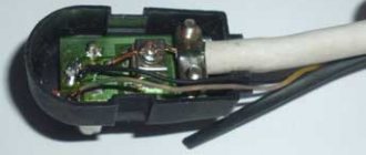
The industrial adapter for connecting to a TV is connected to the power supply with a two-core wire and has two terminals for connecting the antenna cable. To connect the cable, you need to cut it correctly. The cable that will be connected to the antenna consists of a central core, enclosed in plastic insulation, and a shield braid, which, in turn, is enclosed in insulation.
How to make a power supply from energy-saving lamps
In order to connect the cable to the adapter, you must first carefully trim the outer insulation with a sharp knife at a distance of 2 cm from the edge, being careful not to trim the shielding conductors. Next, the insulation is pulled off the cable. Stepping back 15 mm from the edge, cut off the screen. The central wire with insulation remains. Now, stepping back 1 mm from the screen, very carefully trim the central insulation to a depth of several millimeters. By bending the cable several times at the cut site, you need to ensure that the insulation bursts in a circle. Now it needs to be removed from the core.
Important! You cannot cut the insulation to its full depth, since the central core will break at the point of the cut.
Cable cutting
The cut cable is inserted under the terminals of the adapter so that the core falls under the fastening nut in the central terminal, and the shielding braid lies under the wide terminal. Now you can tighten the terminal screws. The connection is ready.
Note! Do not allow at least one of the cores of the shielding braid to come into contact with the central terminal. The power supply will not fail (the microcircuits are protected against short circuits), but the supply voltage will not be supplied to the antenna amplifier.
Before connecting the antenna cable, it is advisable to check the output voltage of the unit. Its values must be within the specified norm and in no case more.
First DIY antenna: whip
This is definitely the simplest antenna. Essentially it is a piece of wire, 1/4 wavelength long. We take a piece of cable and protect its end under the plug.
Then we remove the shielded layer. We bend it to the transition and use a ruler to measure 12.8 cm (1/4 wavelength) and cut off the excess.
Expert opinion
It-Technology, Electrical power and electronics specialist
Ask questions to the “Specialist for modernization of energy generation systems”
DIY beer can antenna for digital TV: how to make an over-the-air receiver for DVB-T2 channels But in order to reduce the mathematical calculations required to calculate the value of resistor R2, every time we need a certain voltage, we can use standard resistance tables , as shown below, which give us the output voltage of the regulators for various ratios of resistors R1 and R2 using the resistance values of E24,. Ask, I'm in touch!
Basic faults
DIY power supply for 12V screwdriver
Amplifier power supplies rarely fail so much that they cannot be repaired. The most common loss of filter capacitance is observed. This malfunction manifests itself in the form of wave-like image distortions due to the penetration of voltage ripples into the amplifier and antenna input of the TV. The reason is usually a poor quality capacitor. Externally, it will have a convex end (must be flat). For repairs, it is enough to install a similar one with a capacity of 220-500 µF at a voltage of 35-50 V.
The absence of output voltage when there is a stabilizer chip at the input indicates a malfunction of the latter. For replacement, you can install any similar microcircuit (analogues were indicated above).
In cases of network voltage surges, the step-down transformer fails. Unfortunately, repairing it will require rewinding the windings, which is difficult to do at home. But if the transformer windings are made on separate coils, then it is possible not to resort to rewinding. Typically there is a fuse built into the primary circuit. To get to it, you need to carefully, trying not to damage the conductors, cut off the outer insulation of the primary winding, which is wound with a thin wire and has a large number of turns, and therefore is much larger than the secondary. A fuse looks like a resistor and if it blows, it has infinite resistance (a working fuse has zero resistance). A faulty fuse is bridged with a thin wire with a diameter of 0.05-0.07 mm.
The diode bridge is made on rectifier diodes with a large margin of voltage and permissible current, so it almost never fails.
Much more often, the junction between the cable and the adapter becomes loose, resulting in loss of contact with the central core, or short circuit with the shielding braid. In this case, you need to connect the antenna cable efficiently and reliably.
To summarize, we can say that most consumers should not see a problem in how to properly connect the power supply or even repair it themselves. The most important thing is attentiveness, accuracy and desire.
Check the result using a multimeter
Once the circuit has been designed and connected, it makes sense to test it and check the characteristics of the resulting design. To do this, you need to have a tester - a multimeter or any other similar device.
Check the following settings:
- The characteristic impedance of the cable should not exceed 75 Ohms.
- The difference between the braid of the coaxial cable and the central core should be several tens of ohms. If the device shows “0”, it means there is a break or short circuit.
- When connecting the central core and braid, the device should show infinity, that is, the maximum of the scale. But if both the braid and the core are disconnected from the antenna and shorted to each other, the result should be zero.
If all 3 tests are passed, then the amplifier is connected correctly.

