Someone is already familiar with the situation when a working computer suddenly turned off for no apparent reason, and after power was restored, it turned off again a few minutes later. A common question that arises at this moment is whether you can fix your PC yourself?
Sometimes replacing a power supply is associated with switching to new components, and sometimes with assembling a new PC. In all these cases, certain knowledge of the PC structure and methods of connecting the power supply to the computer is required.
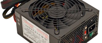
How to connect a power supply to a computer
When is it necessary to replace the power supply?
Problems that a user may encounter if the power supply is faulty and requires its replacement:
- Irregular PC shutdowns or reboots.
In such cases, the power supply is “on its last legs” and will soon fail completely, not allowing the PC to turn on until it is replaced. The user may have a few days before the power supply fails, but there is no guarantee of this. Power supply failure is possible due to frequent reboots and irregular computer shutdowns. - The smell of burning.
Sometimes the power supply emits a burning smell, which is a common sign that you need to stop using your PC and replace the power supply. However, burning smells can also come from bad (swollen) capacitors on the motherboard or from a very hot processor or video card. If it is not possible to determine where the smell is coming from, it is best to have your PC checked by a specialist. The burning smell may be due to a broken power supply or come from swollen capacitors on the motherboard - "Broken" wires. Although this problem is not very common, wires that are excessively bent or have broken insulation can lead to problems with power to the PC. Although these wires can be repaired yourself, it is usually recommended to purchase a new power supply or replacement cables.
Wires that are bent or have torn insulation can cause power problems with your PC. - Computer freezes". In rare cases, the computer may stop working without shutting down. Sometimes this is caused by a faulty power supply, but more often it is caused by problems with the motherboard, hard drive, or RAM. If the PC freezes are due to problems with the power supply, freezes can be avoided by purchasing a high-quality power supply instead of an unknown brand power supply.
These initially small problems can lead to gradual or sudden failure of the PC power supply.
Reference! Sometimes the problem with a PC is not related to the power supply, but to loose fastenings of its power wires. In this case, you need to open the PC case and make sure that all wires are tightly connected to their connectors.
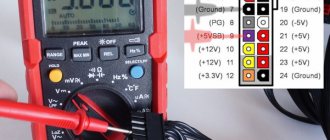
About the cross-section of wires coming out of the computer power supply
Although the currents that the power supply can supply to the load amount to tens of amperes, the cross-section of the output conductors, as a rule, is only 0.5 mm2, which allows current transmission through one conductor of up to 3 A. You can find out more about the load capacity of the wires from the article “On choosing a wire cross-section for electrical wiring.” However, all wires of the same color are soldered to one point on the printed circuit board, and if a block or module in a computer consumes more than 3 A of current, voltage is supplied through the connector along several wires connected in parallel. For example, voltage +3.3 V and +5 V is supplied to the motherboard via four wires. This ensures that up to 12 A of current is supplied to the motherboard.
How to disconnect the old power supply
Step 1. Gather the necessary tools. You may need one Phillips screwdriver to unscrew the PC case wall screws.
To remove the wall of the PC case, prepare a Phillips screwdriver to unscrew the screws
You may need another screwdriver with a less sharp tip to remove and install the power supply - to do this, you need to inspect the slots of the power supply mounting screws (marked in red).
We inspect the slots of the power supply mounting screws in order to prepare a screwdriver with a less sharp tip for removing and installing the power supply
Step 2 . Before disassembling your PC, you need to relieve static electricity from your body by briefly holding the water tap.
Touch the water tap to remove static electricity from the body
Reference! In dry air, especially in winter and in contact with synthetic fabric, electrical potential accumulates on the body, causing a discharge (spark) when touching the PC case, which can damage its components.
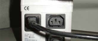
Step 3. Turn off the switch on the back of the PC (if equipped), and also unplug the PC power cord from the outlet.
Turn off the switch on the back of the PC
Unplug the PC power cord from the outlet
Step 4. Disconnect all connectors of external devices from the PC, remembering or writing down the disconnection sequence. It is important to note that some connectors have latches with push tabs or screw connections with heads for manual rotation.
We disconnect all connectors of external devices from the PC, remembering or recording the disconnection sequence
System unit without connected external devices
Step 5. Use a screwdriver to unscrew the screws securing the right wall of the PC case - as viewed from the back of the PC case from the side of the connectors.
Using a screwdriver, unscrew the screws securing the right wall of the PC case
It is possible that the cover is not secured with screws, but with special latches. In this case, pull the latches sideways to release the cover.
When attaching the side wall with latches, pull the latches to the side to release the cover
Step 6. Pull the cover 1-2 cm parallel to the PC case to the rear to remove it from the case connectors.
Pull the cover 1-2 cm parallel to the PC case to the rear to remove it from the case connectors
Step 7: Remove the cover from the side.
Remove the cover from the side
The power supply is usually located at the top of the PC system unit.
We find the power supply at the top of the PC system unit
Step 8. Disconnect the power supply wire connectors from the connected devices inside the PC case, remembering or writing down the disconnection sequence.
It is better to start with devices that are “closer” to the user, moving to “farther ones” during the disconnection process.
Disconnect the power supply wire connectors from the connected devices inside the PC case
When disconnecting, it is necessary to take into account that a number of connectors have latches with pressure tabs.
If there is a latch with a pressure tongue, press the tongue and carefully remove it from the connector
Step 9. After disconnecting the power supply, unscrew the 4 mounting screws on the back of the PC system unit to remove it.
Unscrew the 4 mounting screws at the back of the PC system unit to remove it
Step 10: Carefully remove the power supply.
Carefully remove the power supply from the system unit case
This completes the dismantling of the power supply.
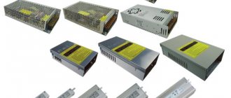
Power supplies for lighting devices
The variety of lighting devices, including floor lamps, chandeliers, table lamps, etc., amazes even those people who have a rich imagination. The emergence of the latest technological developments not only provides high-quality lighting, but also saves energy resources to the maximum extent.
Alternative products are LED strips, which are energy-saving lighting devices. The choice of lamps, the production of which is based on progressive LED technology, is quite wide. These devices have a good design and high-quality technical characteristics.
The use of LED lighting is widespread in advertising, landscape and interior design, car interiors, equipping household appliances, etc. A large assortment of such lamps allows you to choose the appropriate option, be it 40w by 300w or 24w by 250w.
Any selected lighting device requires connection.
For many it may raise a lot of questions. The power supply is the main component of the LED system, which is a compact transformer capable of providing power to the LED strip. Miniature dimensions ensure discreet placement of this device in various suitable places.
How to install a power supply in a computer
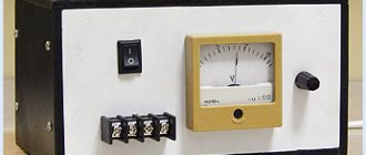
It is necessary to make sure that the installed power supply is optimized for connection to the “local” voltage. To do this, there is a switch on the back panel of some power supplies that allows you to set the power supply voltage to 115 or 230V.
Step 1. Make sure that the 115-230V switch is in the correct position. Usually it is around 230V. If this is not the case, move it with a screwdriver until it stops until the inscription with the required voltage appears. You may need a flathead screwdriver to operate the switch.
We set the desired voltage value on the power supply by moving the switch with a screwdriver until it stops
Step 2: Release static electricity from your body by briefly holding the faucet.
Touch the water tap to remove static electricity from the body
Step 3. Insert the new power supply into the case, turning it so that the 230V power cord connector on it is at the back of the PC and all four holes for the screws of the unit and the case coincide. Screw the block to the housing using a screwdriver.
We insert the new power supply so that all the holes of the block and the case coincide, screw the block to the case using a screwdriver
Step 4. Connect the power supply connectors to the PC devices in the same sequence as they were disconnected previously.
It is better to start connecting from devices “far away” from the user - usually from the motherboard connector.
Connecting the motherboard connector
Next, you can move on to “nearby” devices, most often these are hard drives and other peripheral devices.
Connecting the hard drive
Important! For additional information on connecting devices, please refer to their data sheets and instructions.
Step 5. Close the cover in the same order as it was removed from the PC case.
Close the side cover of the case
Step 6. Tighten the cover screws.
Tighten the cover screws
Step 7. Connect all connectors of external PC devices in the order in which they were disconnected.
We connect all connectors of external PC devices to the system unit
Step 8. Plug the power cord of the system unit into the outlet.
Insert the power cord of the system unit into the socket, turn on the power to the socket
Turn on (if available) the switch on the back of the PC.
Turn on the switch on the back of the PC
Step 9: Plug the monitor (if not already plugged in) into the wall outlet and turn on its power button.
We plug the monitor into a power socket and turn on its power button
Step 10. Turn on the computer using the button on the front panel.
Turn on the computer using the button on the front panel
If nothing happens after you turn on your PC, or you hear a repeating beep, something is not connected correctly or the power supply is not providing enough power. In this case, it is necessary to double-check all connections and, if necessary, refer to the passports of PC devices to clarify the necessary information.
If everything is connected correctly, the computer will start booting as usual. The installation of the power supply on the computer is now complete.
Power supply power
The power of power supplies for LED lamps is determined by a similar indicator of the total load of all devices connected to the circuit. The permissible power level limit may be violated, which causes unstable operation of the device or overheating. A power source whose power level is below the maximum permissible can be connected to the tape.
The power reserve of the power supply for the LED strip is large, so its cost increases. The principle of current stabilization means that its value remains unchanged for different output voltage options. For example, according to Ohm's Law, a 12v lamp with a power of 1W consumes a current of 0.83 A.
An equal amount of current is provided by the driver, connecting to which the LED lamp at the output of the power source will be 12v. If 2 devices are connected to it, which are connected in series, then the current at the output of the circuit is 24V, if 3 lamps - 36V.
They can be connected further until the output voltage is limited, after which the current also drops.
You cannot connect several LED lamps to the driver at once, since the output current must be divided proportionally between the devices. The use of drivers is limited by the complex design of the lighting system, which excludes the possibility of changing the number of connected lighting fixtures.
Tips for replacing and preventing the power supply
The type and power of the installed power supply depends on the type of motherboard and video card of the computer, as well as on the size of the PC case.
Today, the best choice for purchasing a power supply is modular power supplies - they cost a little more than regular ones, but instead of a whole bunch of cables, they only connect those wires that are needed at the moment. This also allows you to organize maximum air flow inside the system unit to cool it.
The best choice for purchasing a new power supply is modular power supplies
As for power, it is better to take it with a small margin, incl. for the future, focusing on 500-750 W, especially if a gaming video card is installed in an SLI or Crossfire configuration.
For a computer with a powerful video card, you need a powerful power supply of at least 500 W, or better yet, more.
However, in the case of an inexpensive system with built-in video, a 300 W power supply will do.
A 300W power supply is used for a computer with a low-cost system with built-in video.
To extend the life of the power source, it is necessary to periodically clean it from dust accumulated inside using a vacuum cleaner or blowing an air bottle through the holes. This will protect the power supply from overheating. It is also important not to twist power cords inside or outside the PC case. These measures will ensure uninterrupted operation of the power source for many years.
Operating principle of the lighting device
The LED strip connection diagram is easy to use. The device is powered by 12v power sources. To convert the mains voltage to 220V, you need a power source with a current stabilizer, that is, a driver, which is an adapter. These devices, which have differences, are characterized by different ways of functioning.
Many types of LEDs require a voltage of about 2-3 V, and LED devices are powered by 12v sources.
Single LEDs are connected in series, and the power supply circuit itself operates in the presence of a limiting resistor. It is current that is required to power the LED. When it drops in the circuit, current flows through all the elements, that is, these same 2–3 V are needed for the operation of the device.
LEDs are devices that are sensitive to the amount of current that needs to be stabilized. Otherwise, exceeding it will negatively affect the service life of the device. Having figured out what kind of power supply is needed for LED lighting, you can ensure stabilization of the voltage of the current source.
All semiconductors are characterized by an increased level of temperature dependence. Tape is the basis of electronic temperature meters. If the temperature of the external environment changes, then at the same time there is a change in the current flowing through the lighting device, provided that the input supply voltage of the LED strip is constant.
The use of stabilizers is due to the fact that LED lighting is often necessary where the range of temperature fluctuations is not too high. Another advantage of using stabilizers is the parallel connection of lighting fixtures. When the voltage drops in such a circuit, the current begins to increase. Drivers are usually used for outdoor lighting because temperature fluctuations are large.
Series-parallel connection of voltage elements.
Power supplies are switched in a series-parallel circuit to increase both current and voltage. In this case, they are based on the fact that parallel connection increases the current strength, and series connection increases the total voltage. Figure 3.13 shows examples of series-parallel circuits for connecting batteries.
Figure 3.11. Series-parallel connection of batteries.
DID YOU LIKE THE ARTICLE? SHARE WITH YOUR FRIENDS ON SOCIAL NETWORKS!
Related materials:
- Voltage sources
- Applied voltage and voltage drop across a circuit section.
- Common wire or ground.
Comments
#42 ExTpABepT 09.10.2019 06:34 If we exclude all sorts of balancers and the like, I have 2 power sources 1. 10V, 1A 2. 5V, 0.5A what voltage will I get at the output when connected in parallel (+ to +; - to -)??
Quote
#41 Iiiiiii 06/01/2019 05:09 I quote Vladik:
I need to connect two 3.7 V batteries in series, but how can I charge them if the batteries may have different voltages?
There are balancers for this. Quote
#40 Andr 05/18/2019 05:53 Quote Slava:
I need 12V to power the device. What happens if you connect in series a 9 V 300 mAh “crown” and three 1.2 V 2600 mAh batteries (all rechargeable).
It will work, but when the crown first gives way, the voltage will drop. Quote
#39 Slava 12/18/2018 15:09 I need 12 V to power the device. What happens if you connect in series a 9 V 300 mAh “crown” and three 1.2 V 2600 mAh batteries (all rechargeable).
Quote
#38 Yuriyts 23.11.2018 23:27 Hello, please tell me, is it possible to connect a charger with a secondary winding output of 21 volts to the battery with a full charge output of 24 volts? Thank you.
Quote
#37 Vladimir1987 08/26/2018 06:19 Quoting nick:
Please tell me what current to charge 3 parallel batteries of 1.5V 1000mAh each?
300 mA you can’t go wrong Quote
#36 Vadim 06/06/2018 08:22 Quote Petr:
What happens if you connect two current sources, for example KRONA batteries, to each other? Plus to minus, minus to plus?
It will close and either explode, or heat up and the charge will disappear, or nothing, depending on the amount of electrical voltage Quote
#35 Vladik 02/28/2018 19:09 I need to connect two 3.7 V batteries in series, but how to charge them if the batteries may have different voltage
Quote
#34 Petr 12/18/2017 11:18 What happens if you connect two current sources, for example KRONA batteries, to each other? Plus to minus, minus to plus?
Quote
#33 Signalman 04.11.2016 16:42 Please tell me, I want to assemble a charger for a 24 V and 12 A battery, there are 2 power supplies 24 V and 6. And if they are connected in parallel, will they output the required values or does this not work with the blocks?
Quote
#32 vsb55 10.30.2016 14:07 4pcs. The batteries for the toy are connected in series, I measure the voltage at 6 volts, the current is 0.75A, and I connect a stabilized power supply with a voltage of 6 volts and a current of 2A, the toy does not work, I return the batteries - everything works, why?
Quote
#31 Felix 08/29/2016 17:48 From the text of the article, I didn’t quite understand about the series-impeding connection of power supplies. It would be more accurate to say that I didn’t understand at all. After all, the connection of elements with poles of the same name is a parallel connection. What is consistently obstructive? Can you draw a diagram?
Quote
#30 Maksimillian 05/10/2016 08:09 Good time! There is a controlled machine. 6 AA durasillers are connected in series. The multimeter in DCA 200m mode gives 42.1. What parameters can you use to select a battery? To give the same parameters, or even better Thanks for your attention 
Quote
#29 Mmmmm 11.21.2015 19:07 I quote mm:
Tell me, if you connect a 12 V battery and a 16 V power supply in parallel, what voltage will ultimately be applied to the load?
I'll join the question.
Only the battery is 11.1 (7600 mA) and the unit is 19.2 2a. In my case, this is a chance to power the laptop. The power circuit has burned out. Quote #28 Alex42ru 08/10/2015 16:31 What happens if you connect 6 solar panels mixed, two in series + two in series + two in series? One produces a voltage of 2.5 V, a current of 25 mA. How much voltage will there be and how many amperes will there be?
Quote
#27 nick 06/22/2015 08:46 Please tell me what current to charge 3 parallel batteries of 1.5V 1000mAh each?
Quote
#26 Administrator 05/17/2015 00:45 I quote Agatha:
Three identical batteries connected in parallel are connected to an external resistance. How will the current through this resistance change if the polarity of one of the batteries is switched?
See Kirchhoff's second law: Quote
#25 Agata 04/27/2015 18:37 Three identical batteries connected in parallel are connected to an external resistance. How will the current through this resistance change if the polarity of one of the batteries is switched?
Quote
#24 Tihogrom 04/19/2015 22:04 Current when batteries and accumulators are connected in series. How it works in practice: we take the tester, set it to “10A” and measure the current of one (!!separate!!) battery or accumulator, we get from 2 to 4 Amperes. We connect the sequence. 3 similar batteries or accumulators and measure their total current... we get from 5 to 10 Amperes. It is extremely important for beginners to understand this! To understand why, instead of current, we imagine a flow of water, batteries as pumps, and conductors as pipes.
Quote
#23 Administrator 04/13/2015 17:25 I quote Rolin:
Sorry for the possibly stupid question: I have a radio-controlled car. I want to increase the battery capacity. Initially there are 4 batteries connected in series, I want to add 4 more batteries in parallel. how to do this correctly?
Connect four new batteries in series, and then connect this battery to the first (standard) battery in parallel.
Only the batteries must be of the same capacity. Quote #22 Rolin 04/08/2015 12:23 Sorry for the possibly stupid question: There is a radio-controlled car. I want to increase the battery capacity. Initially there are 4 batteries connected in series, I want to add 4 more batteries in parallel. how to do this correctly?
Quote
#21 Administrator 02/07/2015 16:17 In this case, it is difficult to calculate the current, since you do not know the internal resistance of the battery, which depends on many factors, including the degree of discharge. It is easier to put an ammeter in series in the circuit and measure the current.
Quote
#20 Roma 02/06/2015 03:17 and if you need to calculate what current will flow through a connected 21 V battery (nom. 24.8), if it is charged with a voltage of 30 V. I had this problem at work.
Quote
#19 Administrator 01/16/2015 16:50 I quote Igor:
How to ensure the connection of batteries with a voltage of 3.7 volts so that the output turns out to be 12 volts, please explain
Igor, connect three elements in series, you get 11.1 volts Quote
#18 Igor 01/16/2015 03:51 How to ensure the connection of batteries with a voltage of 3.7 volts so that the output turns out to be 12 volts, please explain
Quote
#17 Administrator 12/23/2014 02:29 Not constant, but the same across all elements! Naturally, no one has canceled Ohm's law
Quote
#16 Germont 12/22/2014 08:47 I don’t understand how the voltage can change while the current remains constant if, according to Ohm’s law, they depend directly proportionally?
Quote
#15 Administrator 02/13/2014 15:49 I quote mm:
Tell me, if you connect a 12 V battery and a 16 V power supply in parallel, what voltage will ultimately be applied to the load?
There is not enough initial data to give an answer.
What battery? Power supply load current? Internal resistance of voltage sources? If you want a theory, I described it and explained it in a video tutorial here: In general, what is the purpose of such a connection? Charge the battery? Quote #14 mm 02/12/2014 12:28 Tell me, if you connect a 12 V battery in parallel, a 16 V power supply, what voltage will ultimately be applied to the load
Quote
#13 Sergey 11/30/2013 22:41 I quote Nikolay:
I quote Kirill: And if, when connected in parallel, E1 = 5V, and E2 = 1.5V, then what is the total voltage?
5th century
then a larger value is taken, but what if in a parallel connection E1 = 5V and E2 = 7V? then the total voltage is 12, 5 or 7? Quote #12 Nikolay 05/30/2013 21:22 Quoting Kirill:
And if, when connected in parallel, E1 = 5V and E2 = 1.5V, then what is the total voltage?
5th century
then a larger value is taken Quote #11 Kirill 05/29/2013 07:57 And if, with parallel connection, E1 = 5V, and E2 = 1.5V, then what is the total voltage?
Quote
+1 #10 Administrator 12/04/2012 18:36 In theory, I agree with you 100%; in practice, this problem can be investigated. However, its solution does not have much practical significance; it is easier to install a more powerful battery. In general, a problem for “fanatics” of electrical engineering and for students! In my life I have only encountered a parallel connection of batteries, and that was not a standard one, when in “difficult times for our country” it was necessary to connect smaller capacity batteries in parallel to start diesel generators. The starting currents were large!
Quote
+3 natasha.webuspex 12/03/2012 18:45 My conclusion is the following: parallel connection of batteries is harmful. If there is one low-quality one in the set, it will ruin the whole thing and imprison the good one. natasha.webuspex.ru/dva-istoch nika-toka.htm
Quote
+1 Administrator 12/03/2012 17:27 Quoting natasha.webuspex:
This number will not work with batteries (it will not charge), but for batteries the situation is real, motorists often use this. In this case, the lower emf will act as ballast and will not supply current to the load.
Of course, the battery will not charge, I argue that the battery with a higher emf will be discharged.
And regarding “lighting up”, this is correct. Quote +2 Administrator 12/03/2012 17:05 Quoting Dmitry:
I have a question. What happens if you connect two elements in series and the third in the same way but in reverse polarity?
See Kirchhoff's second law. If you have such a connection, then the voltage across the load will be: Rн=-E1-E2+E3=-12V Quote
natasha.webuspex 12/03/2012 06:13 With batteries this number will not work (will not charge), but for batteries the situation real, motorists often use this. In this case, the lower emf will act as ballast and will not supply current to the load.
Quote
-2 Dmitry 12/02/2012 10:46 I have a question. What happens if you connect two elements in series and the third in the same way but in reverse polarity?
Quote
-1 Administrator 11/29/2012 16:30 I agree, however, this current will lead to the “discharge” of an element with a high voltage to the level of the lowest voltage of a parallel-connected element. And when the voltages become equal, the current between parallel-connected elements will be zero. As for the batteries, one simply charged another connected in parallel. In any case, the expression Itot = I1 + I2 + I3 remains true, it’s just that the current of the element with the lower emf will be negative .
Quote
natasha.webuspex 11/29/2012 09:35 At the same time, you forget that the emf of real batteries differs, so a significant current will arise between the elements themselves. If interested, my views are natasha.webuspe x.ru/dva-istoch nika-toka.htm
Quote
Administrator 11/28/2012 15:21 Dear Natasha, rest assured, everything has been tested in practice! In general, everything is checked using Ohm’s law for the complete circuit. That is, when a load is connected to the circuit, the current will depend not only on the load itself, but also on the internal resistance of the source. The total internal resistance of parallel-connected sources is always less than one, hence the conclusion: the current in the circuit will increase .
Quote
natasha.webuspex 11/26/2012 09:55 With a parallel connection of batteries, the recommendation is questionable.
Quote
Update list of comments
Parallel connection of elements.
When connecting batteries in parallel, their pins of the same name are connected together, that is, plus to plus, minus to minus (Figure 3.12).
Figure 3.11.Parallel connection of batteries.
In this case, the total current will be equal to the sum of the currents of each element:
Itotal=I1+I2+I3
The total voltage when connecting power supplies in parallel will be equal to the voltage of each individual source.
Total = E1 = E2 = E3.
Using additional adapters
The lighting will be complete only if the appropriate connection diagram is followed. Before connecting the LED strip to the power supply, you should take care of a device that allows you to change the intensity of the lighting device. If any of the circuit elements are connected incorrectly, the operation of the backlight will be disrupted.
A dimmer, or an additional adapter for a 12-volt LED strip, is a device that allows you to control the brightness of the light. The use of this device is the main reason for the popularity of LED strips.
The power supply for the LED strip is connected with a dimmer, which eliminates the difficulties of using it.
The use of this circuit allows you to control the flow of light. The dimmable LED strip is connected simultaneously with the main and additional adapters, that is, a dimmable power supply is needed.
Before calculating the connection diagram, it should be taken into account that 12-volt tapes have different power ratings. Since choosing a power supply for a chandelier differs from choosing a transformer for an LED strip, two indicators should be taken into account:
- power;
- voltage.
The first parameter is determined by the length of the led or rgb strip, and the second is about 12 or 24V. To dim the tape, you will need to correctly connect not only the transformer to it. The circuit must include a dimmable power supply, the power of which is 12 or 24V.
This involves using a certain type of dimmer.
For example, for an RGB tape that has 3 colors, a special adapter is required that allows you to mix colors and turn them on separately. If the dimmable power supply is selected correctly, the backlight adjustment functions.
Calculation of power supply for LEDs
When choosing a power supply for an LED strip, you should take into account its technical characteristics. For ease of calculation, the rated power of the device, the length of which is 1 m, is taken as the basis. We select a transformer only after all the necessary calculations have been carried out. To do this, you will need to measure the rated power of 1 lm. tape taking into account its length.
Since we cannot do without a power supply for the tape, we select it by making calculations based on the example given. It is required to connect a sealed type of SMD 3528 tape, which assumes the presence of 60 LEDs per 1 m. The operating voltage is standard - 12V. This type of device has a power of 4.8 W/1m, that is, 4.8 W should fall per 1 m of tape.
Any type of tape has a standard length; it is sold in 5 m reels. In the above case, its power will be 24 W. The calculation will be as follows: 4.8x5=24. The example shows how to calculate a power supply for LEDs, that is, a strip 5 m long, the total power of which is 24 W.
If you mistakenly make a connection using a power supply unit whose power is equal to the power of the lighting device, the transformer may overheat. This can also happen if air access in the required quantity is not provided. If the power of the source feeding the tape is less than the calculated one, the device simply will not turn on due to the fact that the internal protection in the transformer will trip.
When choosing a power supply, calculate the amount of power reserve, which should be 25–30%. The result should be: 24 W + 30% = 31.2 W. The resulting value must be rounded to the standard power supply unit of 30 W.