Dielectrics are substances that do not conduct current or conduct it but poorly. Insulation breakdown is closely related to these substances.
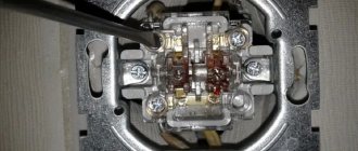
Insulation breakdown is a phenomenon when dielectric parts begin to conduct current, that is, they actually turn into conductors.
If the value of the tension in the electric field of substances increases, this is the cause of breakdowns. All dielectric substances have their own threshold values for electrical insulation strength.
Today we will tell you why the strength of the insulation can become thinner and lead to breakdowns in the insulation.
Theoretical information
Among various gases, air has the greatest technical application as a dielectric, since it is a natural insulation in most electrical structures: transformers, capacitors, air circuit breakers, power lines.
As a dielectric, air has positive properties: it quickly restores its electrical strength after breakdown, slightly changes its dielectric constant, and its dielectric losses are very small (tgδ = 10). Negative properties of air as a dielectric: Low thermal conductivity 0.00025-0.00036 W/cm*C, low electrical strength compared to solid and liquid dielectrics, the ability to moisturize, form oxides, and support combustion. The electrical strength of air is not constant and depends on a number of factors: Pressure, humidity, field shape between the electrodes, temperature, chemical composition of the gas.
The most important are:
1) the shape of the electrodes and the scheme for connecting them to the circuit, which determines the nature of the field in the gap between the electrodes;
2) air density and humidity;
3) the type of applied voltage (constant, alternating industrial frequency, high frequency and pulsed).
Mechanism of gas breakdown in a uniform field.
Gases at small values of electric field strength have extremely low conductivity, since the number of electric charge carriers is in the atmospheric air and therefore, when a small potential difference is applied to the air gap, a current will flow in it, almost imperceptible and not affecting the insulating ability of the air.
A small number of positive and negative ions and electrons contained in the gas, which, like neutral gas molecules, are in random thermal motion, when exposed to a field, receive some additional speed and begin to move, depending on the sign of the charge, in the direction of the field or against it. In this case, the charged particle receives energy.
W=q*Uλ
A magnetic field
Where q is the charge, Uλ is the potential difference at the mean free path.
If the field is sufficient, then we can assume that
Uλ=E*l,
Where E is the field strength, l is the average distance traveled by a charged particle without collision, that is, the mean free path is λ.
From here
Instruments for insulation quality control
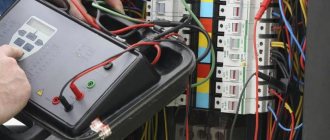
The choice of instruments for monitoring the quality of insulation depends on the type of electrical equipment being examined, cables, test method and conditions. When choosing meters, you should pay attention to the following factors:
- permissible measuring range of the control and measuring device, electrical safety category (CAT I...IV);
- parameters of the electrical system under study (DC/AC voltage at the input/output, load current, frequency, power), the possibility of turning off the power supply to the equipment during research;
- properties of the insulation material (thermal, dielectric);
- environmental parameters (humidity level, temperature);
- Possibility of access to the equipment under test (contact, remotely).
Universal meters of electrical parameters - multimeters, megohmmeters. For household, office and industrial low-voltage electrical installations and wires, CAT I, II meters are sufficient; for high-voltage power lines or distribution cells - at least CAT III (1000 V).
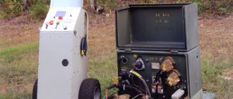
To test the insulation of cables and electrical equipment with direct/alternating high voltage, T99/1, T26/1, MMG5/10, HPG 50/70 units with devices for converting defects (burning) are used. For remote detection of defects in underground cable conductors and estimation of the distance to a fault, shock pulse generators RSP 3, PWG 2000 and reflectometers STELL REIS-205, STELL REIS-305, STELL REIS-405 are popular.
STELL-RAYS 405 reflectometer for checking cables
The indisputable advantages of thermal imagers of the Testo 868/871/872/882/885 line are compactness, mobility, and ease of use. Fluke TiX500/580 thermal imagers have an accuracy of 0.025 °C and an extended measurement range of up to +400 °C.
Electrical porcelain
It is the most common ceramic electrical insulating material. The composition of porcelain includes: kaolin - white clay, fire clay, quartz and feldspar. The production of porcelain products consists of the following operations: grinding the components of porcelain and mixing them with water into a homogeneous mass. By pressing, grinding, casting into plaster molds or extruding from this mass, products of the desired configuration are obtained. To remove excess water, the products are dried, then they are covered with a glassy mass - glaze, which reduces the hygroscopicity of porcelain, gives a certain color to the products and creates an even, smooth surface during firing. After glazing, the product is dried again and fired in ovens at a temperature of 1320 - 1450 ° C. Porcelain is characterized by high heat resistance, resistance to electric arcs and very low water absorption. Linear (suspension and pin) insulators, stationary (support and bushing) insulators, hardware insulators, installation porcelain products (rollers, parts of fuses, cartridges, plugs, etc.) are made from porcelain. Electric strength of porcelain 6 – 10 kV/mm; ε = 5 – 6.5. In addition to porcelain, another ceramic material is used - steatite, made on the basis of the mineral - talc. Soapite, compared to porcelain, has higher electrical insulating and physical-mechanical properties.
Vacuum as an insulator.
When metal electrodes are placed in a gas with a pressure of less than 10-2 Pa, there are not enough gas molecules to generate a noticeable current in the interelectrode gap, and in this case they speak of high vacuum insulation. Ionization of residual gas molecules upon collision with electrons or positively charged ions emitted from the electrodes rarely occurs at such pressures. Under high vacuum conditions at a constant voltage below 20 kV, breakdown may not occur on the cathode surface at a field strength of up to 5 MV/cm, and at the anode at a field strength several times higher. However, at higher voltages, the cathodic gradient at which breakdown occurs rapidly decreases. Breakdown between metal electrodes in a vacuum occurs due to the exchange of charged particles between the cathode and anode. An electron emitted from the cathode is accelerated by the electric field and strikes the anode, knocking out positive ions and photons. Positive ions and some photons fall on the cathode; The ions are accelerated by the electric field and cause the emission of secondary electrons. At a certain critical value of voltage and electric field gradient for a given electrode material, this process becomes unstable and spark breakdown occurs.
High-vacuum insulation is particularly widely used in electronics, both for accelerating low-energy electrons in conventional vacuum devices and for high-voltage applications in X-ray instruments and nuclear research accelerators.
conclusions
Insulation resistance monitoring
Modern instruments make it possible to evaluate the insulation quality of various equipment and cables with high accuracy and under various conditions. The costs of testing by specialized service organizations or departmental services are offset by reductions in costs for downtime and repair of electrical equipment, as well as compensation to consumers in the event of emergency power outages.
If you need professional advice on checking the insulation of cables and electrical equipment, just send us a message!
What is electrical strength?
Electrical strength for any insulation should be understood as the minimum potential difference applied per unit thickness at which discharges begin to occur. Electric strength is a nonlinear function, the change of which depends on the following factors:
The work of the electric field when moving a charge. operating principle
- Insulation thickness;
- Dielectric constant;
- Temperatures of both the surrounding space and the insulation itself;
- Type of dielectric;
- Type of applied voltage (AC or DC).
Thus, we can say that the insulation strength determines the breakdown voltage. In practice, for each material this parameter is calculated empirically after numerous tests.
Rice. 1. Effect of voltage on a dielectric
The value is measured as V/mm or kV/cm, etc., for example, dry air, on average, has a strength of 32 kV/cm.
However, the strength of the insulation will also depend on the aggregate state of the material:
- Solid dielectrics - the most common in cable and wire products, are intended for the manufacture of insulation of cores, device housings, gaskets, etc. After a breakdown or micro-breakdown, the insulation is destroyed, channels are formed through which a repeated breakdown will occur at a lower voltage.
- Liquid dielectrics - the most common option is transformer oil, used in transformers, switches, and high voltage cables. Due to their movable structure, they have the ability to recover, which makes them excellent in oil circuit breakers, where the insulation simultaneously extinguishes the arc and is then restored.
- Gaseous insulation - air is used around the windings of a transformer or other electrical apparatus, the same can be said for some types of high-voltage circuit breakers. But modern devices often use SF6 gas or nitrogen. Gases are also easily restored after a breakdown.
Physically, the electrical strength of dielectrics is ensured due to the absence of free charge carriers in the material. Dielectric molecules hold electrons so firmly in their outer orbits that even applied voltage cannot remove them from their orbits. Of course, if we consider the ideal option - the arrangement of the material between two plates to which voltage is applied, then it will not flow through it. However, all atoms will receive additional energy, which will create a greater electric field strength, both in the entire solid insulation and in each individual atom.
But, if between the above plates you place not one piece of dielectric, but two from different materials, or half from air and the other from plastic, then the electric field strength in these materials will differ due to the fact that they have different dielectric constants. This is one of the most important factors in reducing electrical strength.
Absorption coefficient
When measuring resistance or absorption coefficient, the state of the insulating material is judged by the difference in resistance indicators of elements of the same type or by changes in parameters over a certain period of time. The higher the absorption coefficient, the better.
Control measurements at the cable entry
Glass
It is obtained by melting silica - SiO2 (in the form of sand) with oxides of various metals - sodium, potassium, lead, calcium (in the form of soda, saltpeter, borax, various rocks). Glass is an amorphous body, so it does not have a specific melting point. When heated, glass softens and becomes liquid. In this state, glass can be blown, drawn, pressed, or cast. The physical and mechanical properties of glass depend on its composition and processing. If ordinary glass is fragile, then especially tempered glass - stalinite - has high impact strength. Glass is practically waterproof; it is not affected by acids (except for hydrofluoric acid) and alkali. However, glasses containing only alkali oxides (Na2O, K2O) dissolve well in water (liquid glass). The electrical insulating properties of glass are very high. As glass heats up, it quickly loses its insulating properties. In electrical engineering, glass is used to make cylinders for lighting and electronic lamps, insulators, and the like. Glass can be used to produce fibers with a diameter of up to 0.005 - 0.006 mm. The individual fibers are spun into threads. Glass threads (glass yarn) are used for heat-resistant insulation of PSD grade conductors. Electric strength of glass 10 – 40 kV/mm; ε = 5.5 – 10.
Insulating tape
Insulating tape or duct tape is probably familiar to everyone. In appearance, it is a narrow (not always) roll of colored or black material. The inner side of the tape is coated with an adhesive composition for gluing. The tape is used by winding it onto the insulation site with overlapping turns.
Power cables: main types of electrical cables and features of wiring (100 photos)
According to the material of manufacture, insulating tape can be:
- Polyvinyl chloride (PVC)
- Cotton (CB)
The first type of electrical tape is available in a wide range of colors. CB electrical tape is black in color with a characteristic smell of rubber or bitumen.
PVC electrical tape
PVC electrical tape is made from vinyl by applying an adhesive composition to one side of the tape. The width of PVC insulating tape is from 15 to 50 mm. The advantages of PVC electrical tape are its high elasticity. Disadvantages in changing its properties with decreasing and increasing temperature. PVC electrical tape is excellent, but its use does not extend beyond low voltages.
HB electrical tape
CB electrical tape is characteristically black in rolls 15-50 mm wide. It is made from cotton tapes impregnated in rubber and applying an adhesive layer to one side. The combination of cotton (possibly fiberglass) makes the cotton tape resistant to temperature fluctuations and its use extends to networks with voltages over 1000 V.
In physics
When the voltage in the conductors increases, the strength values in the electric fields also increase accordingly. The insulation breakdown itself occurs in conductors, which can be cable cores or plates.
In this case, the strength of electricity is measured in kilovolts per millimeter or kilovolts per centimeter. This is suitable for flat cables made in the form of tapes or plates with uniform insulating layers. A great example is the paper capacitor.
Breakdowns in insulation cause short circuits in the electrical network. For insulation layers, its insulation strength values are a key parameter.
You can read about the exact strength of insulating layers on certain electrical installations or electrical equipment in the relevant sections of GOST.
Electrical strength of air gaps
Fundamentals > Electrical Materials > Dielectrics
Electrical strength of air gaps Under normal conditions (pressure 0.1 MPa; temperature 293 K, absolute humidity 11 g/m3), the discharge voltage of the air gap between flat electrodes (uniform field) s is the distance between the electrodes, m. Dependence of discharge voltages on the distance between electrodes for gaps with a sharply inhomogeneous field (rod - rod, rod - plane) at voltages with a frequency of 50 Hz and pulsed (50%) are shown in Fig. 6-1 and 6-2. Under conditions other than normal, where is the relative density of air; p—pressure, Pa; T—temperature, K; k is a correction factor for taking into account air humidity (Fig. 6-3). For gaps with a weakly inhomogeneous field (balls), the coefficient k is taken equal to unity. At voltages whose amplitudes are less than 141 kV, the percentage correction for humidity decreases compared to that indicated in Fig. 6-3, proportional to the voltage amplitude. For pre-discharge times less than 10 μs, the percentage correction for humidity decreases in proportion to the value of the pre-discharge time, i.e., relative to 10 μs.
Rice. 6-1. Discharge voltages for rod-to-rod and rod-to-plane air gaps at 50 Hz.
Rice. 6-2. Discharge 50% impulse voltages for air gaps rod-rod and rod-plane.
Rice. 6-3. Correction factor k to take into account air humidity (according to GOST 1516-731)
The conditions for the occurrence of a corona discharge in the case of a sharply repeated field are described in the section. When choosing insulating distances through the air in structures with sharply non-uniform fields, you should use the discharge characteristics of gaps with rod electrodes according to Fig. 6-1 and 6-2 (as the most unfavorable case). For high-voltage devices, the minimum insulation distances through the air can be taken equal to: where Un in kVrms. If it is necessary to increase the electrical strength of air gaps in order to reduce distances when there is not enough space, measures are taken to level the electric field to a slightly non-uniform one, for which: a) increase the radii of curvature of the electrodes so that they exceed the interelectrode distance; b) provide for careful processing and elimination of any local irregularities on the surfaces of the electrodes; c) provide measures against contamination and dusting of the surface of the electrodes. The choice of insulating distances in the case of a weakly inhomogeneous field can be made according to the discharge characteristic for a gap with ball electrodes of a sufficiently large diameter (Fig. 6-4). The minimum insulation distances in distribution installations are standardized by the Electrical Installation Rules.
Rice. 6-4. Discharge voltages for an air gap with a weakly inhomogeneous field (balls with a diameter of more than 100 cm, one ball per earth) at voltages - constant, alternating 50 Hz and pulsed.
See also this section on websorClassification of dielectrics Polarization of dielectrics Electrical conductivity of dielectrics Breakdown of dielectrics Electrical strength of air gaps Discharge along the surface of a solid dielectric Discharge in oil
Liquid dielectrics.
Organic compounds, in particular hydrocarbons, are widely used as liquid dielectrics. Hydrocarbons are characterized by low dielectric constant (from 2 to 4) and moderately high electrical resistivity (approx. 1012 OhmHcm). Because hydrocarbons do not contain oxygen or nitrogen, they are chemically stable and therefore suitable for use in high electric fields in which ionization processes increase chemical instability. Examples of liquid dielectrics include cyclic hydrocarbons such as benzene (C6H6) or acyclic compounds such as hexane [CH3 (CH2)4CH3]. Most hydrocarbons occur as mixtures; the chemical composition and structure of their constituent components are not precisely known. These include, in order of increasing viscosity, petroleum ether, paraffin oil, transformer oils, paraffin and various waxes.
Some halogen derivatives, such as chloroform (CHCl3) and carbon tetrachloride (CCl4), are dielectrics. Liquid inorganic dielectrics include liquefied gases such as carbon dioxide and chlorine.
An important advantage of liquid dielectrics is their ability to restore their properties after a spark breakdown and their ability to conduct heat, which is important for transformers
Reasons for the decrease in electrical strength
The most negative impact on the dielectric strength of insulation is exerted by alternating voltage and temperature. With alternating voltage, that is, a voltage that changes from time to time, for example, a power plant outputs 220 kV into the line, due to a technical malfunction or scheduled repairs, the voltage value is reduced to 110 kV, after repair it becomes 220 kV again. This is alternating voltage, that is, changing over a certain period of time. Due to the fact that in the Russian Federation 50 percent of electrical installations for transmitting electricity have already exhausted their service life (and it is 25-30 years), alternating voltage is a fairly common occurrence. The average value of this voltage is determined using the graph:
Or determined by the formula:
The heating temperature of the cable, due to the flow of electric current, significantly reduces the service life of the conductor (so-called insulation aging occurs). The dependence of the breakdown voltage at different temperatures is shown in the graph:
Gas connection
Not everyone knows how gas and insulating layers on electrical equipment are connected. Moreover, they are closely related to each other, since gas is considered a good dielectric substance.
Gas provides insulation on electrical equipment rated for large numbers of volts.
For such insulation the following is used:
- Air.
- Nitrogen.
- Sulfur hexafluoride.
Sulfur hexafluoride can be called SF6 gas and is one of the best ways to provide insulation. To distribute and receive electricity more than one hundred kilovolts, special distribution devices are used.
Thanks to such devices, it is possible to create taps at electrical substations, or to create the reception of electrical energy in large cities.
For the distribution device, SF6 gas is used. It is used not only as an insulation layer: gas can occur when operating wires filled with oil. When voltages with different values pass through, heating and cooling occur.
“Thermal degradation” refers to cables where the insulating layer of paper is impregnated with an oily substance. When cellulose decomposes, substances such as methane, gases (carbon dioxide and carbon dioxide), and other volatile substances are formed.
When the insulation layer begins to age, ionization breakdown may occur. For this reason, today conductors with insulation made of impregnated paper are used less and less often, and if they are found anywhere, then in networks up to thirty-five kilovolts.
Electrical Strength - Air
| Crown on a metal ball. Breakdown and overlap. solid insulation. |
The electrical strength of air, like other gases, is greatly influenced by pressure. As the pressure increases, the electrical strength of gases increases significantly (compare p.c. This circumstance is used in some electrical devices and cables. As the pressure decreases, the electrical strength of air (and other gases) decreases; however, when a very deep vacuum is reached, the electrical strength again increases significantly.
| Voltage and current during partial discharge (PD and air. |
At atmospheric pressure, the dielectric strength of air is known to be lower than insulation. Under certain conditions, the field strength in the air inclusion can exceed a critical value (on average 33 sq/cm), and then its breakdown will occur.
| Dependence of the maximum shutdown current of an air circuit breaker on the ratio of the area of the outlet to the distance between the contacts (according to Laboure. | Dependence of the shutdown power of an air circuit breaker on pressure (data from Edsel and Stobbs. |
The effect of pressure on the electrical strength of air largely depends on the nature of the electric field between the contacts.
The effect of pressure on the electrical strength of air largely depends on the nature of the electric field between the contacts. Only in a uniform field does the breakdown voltage of air at a frequency of 50 Hz increase with increasing pressure. In a non-uniform field, which usually occurs in existing arc-extinguishing devices, at low pressures the breakdown voltage first increases with increasing pressure, but with a further increase in pressure it begins to decrease and then increases again.
| Wire brand PR. |
Due to the fact that the electrical strength of air is significantly less than that of solid and liquid dielectrics, the distance between non-insulated (bare) current-carrying parts under high voltage, for reliable operation of the installation, must be chosen significantly greater than the distance between current-carrying parts separated by a solid or liquid dielectric .
As absolute humidity increases, the electrical strength of air also increases. This phenomenon has little effect in homogeneous or weakly inhomogeneous fields. But it should be taken into account in sharply inhomogeneous fields, especially with precise measurements. However, a more important parameter is relative humidity. If the relative humidity in a given room is high, a damp film forms on the surface of solid materials. As a result, the surface resistance of the material decreases and charges flow off the surface. The formation of a wet film on a surface depends on the quality of the surface, whether it is hydrophobic or hydrophilic. Volume resistivity also depends on relative humidity.
| Dependence of the discharge gradient Ep (amplitude values in a uniform field on the distance between the electrodes I at different relative air densities b. |
For very long gaps, the electrical strength of air at atmospheric pressure (61) tends to a value of 2 45 kV / mm, while at the same pressure, but with a distance between the electrodes of 10 mm, the discharge gradient will be approximately 3 1 kV / mm. It should be noted that even in a uniform field, the discharge gradients do not remain strictly constant, but decrease as the length of the gap increases. At a compressed air pressure above 1 MPa, the effect of field emission becomes more noticeable, leading to very significant deviations of the discharge characteristics from Paschen’s law, as a result of which the field strength E ceases to change proportionally to the pressure and therefore the difference in the discharge voltages of industrial frequency at short-term and its long-term application. In view of this, obviously, it makes no sense to talk about discharge gradients of compressed air even in a uniform field in isolation from the specific length of the intercontact gaps and the actual gas density.
The field strength is close to the electrical strength of air.
Which electrode shape has the greatest electrical strength of air?
A decrease in pressure leads to a drop in the electrical strength of the air, which can cause the air gaps to close and a discharge to occur. A change in atmospheric pressure also affects the capacity of the air condenser, thereby causing a change in the output parameters of the equipment as a whole.
Acceptable insulation resistance values
The table below shows the minimum permissible insulation resistance values for electrical installations, devices, secondary circuits and electrical wiring with voltages up to 1000 V.
These values are given in accordance with the PUE (Rules for the Construction of Electrical Installations) Chapter 1.8 and PTEEP (Rules for the Technical Operation of Consumer Electrical Installations) Appendix 3; 3.1
| Item name | Megger voltage, V | Insulation resistance, MOhm | Note |
| Electrical products and devices for rated voltage, V: | Must comply with manufacturers' instructions, but not less than 0.5 | When taking measurements, semiconductor devices in products must be shunted | |
| up to 50 over 50 up to 100 over 100 up to 380 over 380 | 100 250 500 — 1000 1000 — 2500 | ||
| Switchgears, boards and conductors | 1000 — 2500 | at least 1 | Measurements are taken on each section of the switchgear |
| Electrical wiring, including lighting networks | 1000 | not less than 0.5 | When making measurements in power circuits, measures must be taken to prevent damage to devices, especially microelectronic and semiconductor devices. In lighting networks, lamps must be unscrewed, sockets and switches connected |
| Secondary circuits of switchgears, power supply circuits for drives of switches and disconnectors, control circuits, protection circuits, automation, telemechanics, etc. | 1000 | at least 1 | Measurements are made with all connected devices (coils, contactors, starters, switches, relays, instruments, secondary windings of voltage and current transformers) |
| Cranes and elevators | 1000 | not less than 0.5 | Produced at least once a year |
| Stationary electric stoves | 1000 | at least 1 | Performed when the stove is heated at least once a year |
| DC buses and voltage buses on control panels | 500 — 1000 | at least 10 | Produced with disconnected circuits |
| Control circuits, protection, automation, telemechanics, excitation of DC machines for voltage 500 - 1000 V, connected to the main circuits | 500 — 1000 | at least 1 | The insulation resistance of circuits with voltages up to 60 V, powered from a separate source, is measured with a megohmmeter for a voltage of 500 V and must be at least 0.5 MΩ |
| Circuits containing devices with microelectronic elements designed for operating voltage, V: | |||
| up to 60 over 60 | 100 500 | not less than 0.5 not less than 0.5 |
Conditions during measurements
Measurements are carried out indoors at a temperature of 25±10°C and a relative air humidity of no more than 80%, unless other conditions are provided for in the standards or technical specifications for cables, wires, cords and equipment.
The value of the electrical insulation resistance of the connecting wires of the measuring circuit must exceed at least 20 times the minimum permissible value of the electrical insulation resistance of the product under test.
It is recommended to measure the insulation characteristics of electrical equipment using the same type of circuits and at the same temperature. Comparison of insulation characteristics should be made at the same insulation temperature or similar values (temperature difference no more than 5°C). If this is not possible, then a temperature recalculation must be made.
Safety requirements
- Before starting measurements, make sure that there is no voltage on the measured object.
- Before starting tests, it is necessary to make sure that there are no people working on that part of the electrical installation to which the test device is connected, to prohibit persons located near it from touching live parts and, if necessary, to set up security.
- Measuring the insulation resistance with a megohmmeter should be carried out on disconnected live parts from which the charge has been removed by first grounding them. Grounding from live parts should be removed only after connecting the megohmmeter.
- When measuring the insulation resistance of live parts with a megohmmeter, the connecting wires should be connected to them using insulating holders (rods).
- When working with a megohmmeter, touching the live parts to which it is connected is not allowed. After completion of work, the residual charge should be removed from live parts by briefly grounding them.
Preparing to take measurements
In preparation for measurements, it is necessary to carry out a number of technical measures in accordance with the Interindustry rules for labor protection during the operation of electrical installations POT R M-016-2001, as well as the requirements of GOST 12.3.019-80 (System of occupational safety standards (SSBT). Electrical tests and measurements . General safety requirements). When conducting tests, follow the requirements of the Labor Protection Instructions when measuring insulation resistance.
- Measurements should be carried out with megohmmeters of various types and voltages, depending on the requirements of the test voltage.
- Check the validity period of the state verification on the megohmmeter.
- When performing periodic preventive work in electrical installations, as well as when performing work on reconstructed facilities in electrical installations, the preparation of the workplace is carried out by the personnel of the enterprise where the work is performed.
- Before starting measurements, it is necessary to study the electrical installation of the building and make sure that there is no voltage on the tested object, take measures to prevent access to the tested object by persons not participating in the tests, and, if necessary, assign an observer.
- Disconnect electrical appliances, remove fuses, disconnect devices (circuit breakers, switches), disconnect electronic circuits and electronic devices, electrical parts of an electrical installation with reduced insulation or reduced test voltage.
- Check the serviceability of the megohmmeter.
Megaohmmeters
Analogue-type megohmmeters, for example M4100, ESO202, or digital instruments, which have recently become widespread, are used as measuring instruments.
But regardless of the type, all megohmmeters must have valid documents confirming their verification or certification.
Taking measurements
Insulation resistance measurements are carried out by direct measurement of the resistance between each conductor, one conductor and the remaining conductors connected to each other and relative to the ground (grounding bus).
For cables with a metal sheath, screen or armor - between each current-carrying conductor and the remaining conductors connected to each other and the sheath, screen, or armor.
For electrical installations, measurements are taken between all insulated parts.
In order to exclude the influence of surface currents when measuring resistance, it is necessary to use a three-wire measurement method.
The insulation resistance measured at the test voltage is considered satisfactory if it corresponds to the minimum permissible values given in the table. If the measurement results showed values different from these permissible values, it is necessary to perform repeated measurements by disconnecting cables, wires and cords from the consumer terminals and separating the current-carrying conductors.
The megohmmeter readings are recorded after 1 minute. from the moment the measuring voltage is applied, but no more than 5 minutes, unless other requirements are provided for in the standards or technical specifications for specific cable products or other equipment being measured.
To re-measure, all metal elements of the cable product must be grounded for at least 2 minutes.
When carrying out measurements, the errors caused by the errors of measuring instruments and apparatus, additional capacitances and inductive couplings between the elements of the measuring circuit, the influence of temperature, the influence of external electromagnetic and electrostatic fields on the measuring device, method errors, etc. must be taken into account.
Example of an insulation resistance measurement protocol
Electrical strength.
An increase in air pressure leads to an increase in the corona discharge voltage and the electric field strength at which breakdown occurs for the electrode system under consideration. According to Paschen's law, in a uniform electric field the breakdown voltage will not change if, while reducing the interelectrode gap, the gas pressure in the gap is increased by the same amount. Common gases such as nitrogen, oxygen and carbon dioxide have an insulating ability similar to that of air at atmospheric pressure. Some vapors, especially those containing sulfur, chlorine or fluorine, such as sulfur hexafluoride (SF6), carbon tetrachloride (CCl4) and Freon-12 (CCl2F2), have three times the dielectric strength of air at the same pressure. The effect of pressure on breakdown voltage for some materials is shown in the figure.
The electrical insulating properties of gases are worst at pressures from 1 to 0.01 kPa. The passage of current through a gas at such pressures is accompanied by a bright glow (for example, in mercury or neon lamps). This phenomenon is called a glow discharge.
Methods for quality control of insulation of wires and electrical equipment
An example of a protocol for checking the insulation resistance of cables and wires.
Let's consider the main methods for monitoring the quality of insulation of wires and electrical equipment. Parameters characterizing the quality of insulation:
- absorption coefficient (R60/R15 – ratio of resistances calculated 60 and 15 seconds after applying voltage);
- dielectric loss tangent (tg δ=P/Q – ratio of active and reactive power);
- electrical strength when applying increased voltage 3-35 kV;
- temperature of surface or internal layers of insulation.