The device is in normal conditions if it is installed in the position indicated on the device scale, is in an environment with normal temperature (+20 °C) and is not exposed to an external magnetic field (except the earth's).
Nominal value
of a measuring instrument is called the upper limit of its measurement. The error can be positive or negative.
The relative error when measuring a quantity with a device is the ratio, expressed as a percentage, of the greatest possible absolute error of the device to the measured value of the quantity, that is, the measurement error is equal to the error of the device multiplied by the ratio of the nominal value of the device to the measured value.
The smaller the measured value compared to the nominal value of the device, the greater the measurement error of this value; therefore, the measured quantity must have a value of at least half the nominal value of the device.
Table 1. Symbols of the principle of operation of the device
| System | Design | Symbol | |
| Magnetoelectric (M) | With movable frame | ||
| With moving magnet | |||
| Logometer with movable frames | |||
| Moving magnet ratiometer | |||
| Electromagnetic (E) | With mechanical counter force | ||
| Ratiometer | |||
| Polarized device | |||
| Electrodynamic (D) | without iron | with mechanical counter force | |
| ratiometer | |||
| ferrodynamic | with mechanical counter force | ||
| ratiometer | |||
| Induction | with mechanical counter force | ||
| ratiometer | |||
| Electrostatic (C) | — | ||
| Vibrating | reed | ||
| Thermal (T) | with heated wire | ||
Table 2. Additional symbols indicated on devices
| Name | Characteristic | Designation | |
| Rectifier | semiconductor | ||
| electromechanical | |||
| Converter | electronic | ||
| vibration-pulse | |||
| thermal | isolated | ||
| non-insulated | |||
| Protection against external fields | magnetic (first security category) | ||
| electrical (first security category) | |||
| Type of current | constant | ||
| alternating single-phase | |||
| constant and variable | |||
| three-phase with uneven phase load | |||
| three-phase | |||
| Accuracy class | when normalizing the error as a percentage of the measurement range, for example 1.5 | ||
| the same as a percentage of the scale length, for example 1.5 | |||
| Scale position | horizontal | ||
| vertical | |||
| inclined at a certain angle to the horizontal, for example 60° | |||
| Warning sign | Carefully! The insulation strength of the measuring circuit in relation to the housing does not meet the standards (the sign is red) | ||
| the measuring circuit is isolated from the housing and tested with voltage, for example 2 kV | |||
| Attention! See additional instructions in the passport and operating instructions | |||
| Terminal designations | negative | ||
| positive | |||
| AC (in combined appliances) | |||
| general (for multi-range AC devices and combined devices) and generator (for wattmeters, varmeters and phase meters) | |||
| connected to screen | |||
| connected to the body | |||
| for grounding | |||
Table 3. Advantages, disadvantages and scope of application of devices
| System | Advantages | Flaws | Application area |
| Magnetoelectric | High sensitivity, greater accuracy. Relatively small influence of external fields. Low energy consumption. Low influence of temperature | Suitable for direct current only. Sensitive to overload | Measurement of current and voltage in DC circuits. With thermal converters and rectifiers they are used to measure electrical quantities in alternating current circuits, as well as to measure non-electrical quantities (temperature, pressure, etc.) |
| Electromagnetic | They can be manufactured for high current for direct switching, and are resistant to overloads. Suitable for DC and AC current, simple design | Low accuracy. Dependence of readings on external magnetic fields. Uneven scale | Measurement of current and voltage in DC and AC circuits. It is recommended to be used primarily for measurements in alternating current circuits, since the insufficiently uniform quality of the iron cores reduces the accuracy of instruments calibrated for both types of current |
| Electrodynamic | High precision, suitable for DC and AC current | Dependence of readings on external magnetic fields. Sensitive to overloads. High power consumption. Scale unevenness | Measurement of current, power, voltage, frequency, phase angle in AC circuits, as well as voltage, current and power in DC circuits |
| Thermal | Independence of readings from the frequency and shape of the alternating current curve and external magnetic fields. Suitable for direct and alternating current. Greater sensitivity. Low power consumption | Greater sensitivity to overloads (for devices with a photocompensation amplifier, sensitivity to overloads is significantly reduced) | Current measurement in industrial and high frequency AC circuits |
| Electrostatic | Low power consumption. Independent of frequency, temperature and external magnetic fields. Possibility of direct measurement of high voltages at low and high frequencies (up to 40 MHz) | Dependence on external electrostatic field and air humidity | Voltage measurement in DC and AC circuits |
| Vibrating | Simplicity of design and reliability in operation. Possibility of connecting the device to circuits with different voltages | Vibration of plates from external shocks. Discontinuity of the scale, as a result of which it is difficult to read at an intermediate frequency | AC frequency measurement |
Table 4. Classification of devices according to the method of protection from external fields
| Device | Execution |
| Shielded | With magnetic or electrostatic shield protection from external magnetic or electrostatic fields |
| Astatic | With two identical rotating parts, rigidly fastened on a common axis, acting on which external magnetic fields cause moments of mutually opposite signs |
| Unshielded | Not protected by a magnet or electrostatic shield from external magnetic or electrostatic fields |
Scope of application
An electrical measuring instrument is a necessary device in communications, energy, industry, transport, medicine and scientific research. This device is also used in everyday life, for example, to account for consumed electricity. And if you use special converters of non-electrical to electrical quantities, then the range of application of electrical measuring instruments becomes much wider.
Design and applications of measuring instruments
To measure various indicators of electric current, special instruments are used. Such devices are varied and classified according to several criteria, which allows you to choose the best option. All options form a separate class called electrical measuring instruments.
Electrical measuring instruments are diverse, as they are needed in different fields of activity.
Many instrument options necessarily require a display on which information is displayed. The design also contains a switch or button to control the device. Connectors for connecting cables, a housing, and an on/off button are also elements of electrical measuring instruments.
A display or dial is always present on electric current measuring instruments
Devices of various types are used in the following fields of activity:
- medicine;
- communications and energy;
- Scientific research;
- living conditions;
- transport industry;
- production of any type.
Simple or complex models of devices allow you to measure current strength and other indicators of electricity. For domestic purposes, a simple option is used - an electricity meter, while in industry more complex and professional devices are used. Thus, each type of electrical measuring devices has a specific purpose.
Classification of electrical measuring instruments
One of the essential features of the systematization of such devices is a reproducible or measurable physical quantity. According to it, devices are divided into:
- for measuring the strength of electric current - ammeters,
- measuring electrical voltage - voltmeters,
- measuring electrical resistance - ohmmeters,
- measuring the frequency of electric current oscillations - frequency meters,
- measuring various quantities - multimeters or avometers, testers,
- to reproduce the indicated resistances - resistance stores,
- measuring the power of electric current - varmeters and wattmeters,
— measuring electrical energy consumption - electricity meters, etc.
How to connect
How to connect a voltmeter
Electrical measuring instruments are connected:
The ammeter is connected in series, next to the resistor, near which the current value will be measured.
How to use an ammeter? This diagram is simple enough to understand how to use an ammeter correctly.
Figure 5 shows:
- R – resistor;
- A – current measuring element;
- I – direction of electric charge.
How to use a voltmeter? The electrical appliance has parallel connections in those places where the voltage will be measured.
Figure 6 shows:
- R – resistance element;
- V – voltage meter.
How to use an Avometer? This type (voltmeter-ampmeter) is a combined device. In the case of measuring a current signal, it is connected as an electric charge meter. If voltage is measured - like a voltage meter.
A digital voltmeter-ampmeter is considered more convenient to use. When using electrical appliances, it is necessary to comply with all fire safety rules and for proper operation, take into account all their design characteristics.
Notation system
Abroad, manufacturing plants install their designations on manufactured measuring devices. In Russia and some former republics of the Soviet Union, a unified system of signs is traditional. It is based on the operating principle of a specific device. The main electrical measuring instruments in the designation always have a capital letter of the Russian alphabet, which indicates the principle of operation of the device. As well as a number that indicates the conditional model number. Sometimes you can see the capital letter M, which means that the device is modernized or K (contact). There are other notations. For example, D (electrodynamic devices), N (recording devices), P (measures, devices that measure the parameters of electrical network elements, measuring transducers), I (induction devices), L (logometers), etc.
Accuracy Rates
One of the main characteristics of a device for electrical measurements is its accuracy class. There are several of them. And it is determined depending on the permissible error limit caused by the design features of a single device.
The accuracy of electrical measuring instruments cannot be equal to the relative or absolute error. The latter is not a determinant of accuracy, but the relative one has a dependence on the value of the quantity that has undergone a change, that is, it will have different values for different sections of the scale.
Therefore, the reduced error (ɣ) is used to characterize the accuracy of an electrical device. It is determined by the ratio of the absolute error of a specific device (∆x) to the maximum (or limit) of the measured value (xpr). The resulting value, expressed as a percentage, will be the accuracy class of a particular device:
— ɣ = ∆x / xpr * 100%.
Any electrical measuring device must have an indication of its accuracy class on the scale. According to GOST, it can be 0.05, 0.1, 0.2, 0.5, 1.0, 1.5, 2.5 and 4.0. On this basis, devices can be classified as follows:
- accuracy class 0.05 and 0.1 - exemplary, used for checking precision instruments (for example, laboratory ones);
— accuracy class 0.2 and 0.5 – laboratory, used in laboratories for making measurements and checking technical instruments;
— accuracy class 1.0, 1.5, 2.5 and 4.0 – technical, used for technical measurements.
Electrical measuring instruments: principle of operation
The operation of most electrical measuring instruments is based on the magnetoelectric effect. Electrons moving along the conductor of an electrical circuit form a magnetic field around themselves. The needle of the measuring device moves in it, reacting to the strength of the surrounding field. The weaker the magnetic field, the smaller the needle deflection and vice versa.
If an arrow is suspended in close proximity to a conductor through which no electric current flows, then it can only respond to the Earth’s magnetic field. But if current is passed through the conductor, the needle will already react to the magnetic field of the electric current. Thus, the mechanical deflection of the needle is provoked by electrons moving through the conductor. And therefore, the greater the electric current, the stronger the field it creates and the further the arrow deviates from the initial position. This simple principle is fundamental to most electrical measuring instruments.
One electrical measuring device differs from another not by the measuring deviation of the needle (this does not apply to devices with a digital indicator), but by internal circuits and methods of creating an electromagnetic field. As you know, for electrons to move in an electrical network, a load is required. Therefore, this movement has some differences in ohmmeters, voltmeters and ammeters that have a clamp meter. Devices with such grips “pull” the magnetic field from the plates that form them. In a voltmeter, a resistor is used to produce a magnetic field, which receives a load when voltage is applied to the circuit. An ohmmeter has its own power supply and uses the device it is measuring to generate a magnetic field.
The devices described above carry out measurements in the same way, although the load supply and power sources are different.
The measuring displacement of the needle, provoked by the magnetic field of moving electrons, indicates some division of the scale. There are usually several of them, and each has its own limit for measuring voltage, resistance and current. Some devices have a selector switch for user convenience.
Magnetoelectric measuring mechanism
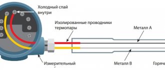
The moving part of the magnetoelectric measuring mechanism (Fig. 1) consists of a rectangular coil (frame) B. The winding of the frame is made of thin insulated copper wire and is placed on an aluminum frame. Two axle shafts are mounted on the frame - cores installed in supports. On one of the axle shafts there are fixed arrows and the ends of spiral springs, through which current is supplied to the frame winding.
Rice. 1. Magnetoelectric measuring mechanism
The sides of the frame are located in a narrow air gap A between the stationary steel cylinder B and the pole shoes N, S. A strong permanent magnet N-S creates a uniform radial magnetic field in the air gap.
F will act on the sides of the frame located in a magnetic field if there is a current in the winding
,
F
(Fig. 2). This creates a torque proportional to the current in the frame. Under the influence of this moment, the frame will rotate through an angle a, at which the torque is balanced by the counteracting moment of the springs. The latter is proportional to the angle of twist of the springs. The angle of rotation of the frame is proportional to the current.
Rice. 2. Obtaining torque in a magnetoelectric measuring mechanism
A calmer
is a device designed to reduce the oscillation time of the moving part that occurs after turning on the device. In the magnetoelectric measuring mechanism, the damper is the aluminum frame frame. When the moving part is rotated, the magnetic flux passing through the frame changes. Currents are induced in the frame, the interaction of which with the magnetic field of the magnet creates a braking torque that provides calming.
The considered measuring mechanism, due to the small cross-section of the springs and winding wire, is manufactured for low rated currents of 10-100 mA or less.
When a magnetoelectric measuring mechanism of the considered design is connected to an alternating current circuit, the torque will change in proportion to the instantaneous current value. With such a rapid change in torque due to inertia, the moving part will not have time to follow the change in torque, and it will deviate by an angle proportional to the average value of the torque over the period. With a sinusoidal current, the average value of the current, and therefore the torque, is zero and the moving part will not deviate. Thus, the considered measuring mechanism is suitable only for measurements in a DC circuit.
How digital meters work
Digital electrical measuring instruments have a high accuracy class (the error varies from 0.1 to 1.0%) and a wide measurement range. They are fast and can work together with electronic computers, which makes it possible to transmit measurement results without any distortion over various distances.
These devices are considered comparative and direct evaluation devices. Their work is based on the principle of converting the measured value into code, thanks to which the user has a digital representation of information. What other electrical measuring instruments are considered digital? These are devices that, when measuring a continuous electrical quantity, automatically convert it into a discrete one, encode it and provide the result in a digital form that is convenient for the user to read.
Ferrodynamic measuring mechanism
The operating principle of this measuring mechanism is the same as the electrodynamic one. It differs from the latter in the presence of a steel core made of sheet steel, on which a stationary coil is superimposed, and a stationary cylinder made of the same steel, which is covered by a moving coil (Fig. 6).
The steel magnetic core strengthens the field of the measuring mechanism, as a result of which the torque increases, which leads to a more durable structure and reduces the influence of external magnetic fields on the readings of the measuring mechanism. The use of steel increases errors from residual induction and eddy currents in the magnetic circuit.
Rice. 6. Ferrodynamic measuring mechanism
Devices located in one housing
These are instruments that use one measurement mechanism to measure several quantities non-simultaneously. Or they have several converters with a common reading device (scale) for all. It is calibrated in units of measured quantities. Most often, combined electrical measuring instruments combine devices that measure the strength of direct or alternating current and electrical voltage (ampere-voltmeters); resistance, direct and alternating current, voltage (avometers or ampere-voltmeters). There are also universal digital electrical measuring instruments that measure DC and AC voltage, inductance and the number of pulses.
An example of such a device is the new development of Aktakom ADS-4031. The device harmoniously combines a function generator, a digital oscilloscope, a frequency meter, an RLC meter and a digital multimeter. In addition to the main five combined devices, the oscilloscope tester, thanks to additional accessories, can be used for a number of other measuring tasks.
Electrodynamic measuring mechanism
The electrodynamic measuring mechanism (Fig. 4 and 5) consists of two coils - fixed A, which has two sections, and movable B, mounted on the same axis with an indicator arrow, air damper wing B and two spiral springs.
When current I
1, through a fixed coil and current
I
2 through a moving coil, an electrodynamic interaction occurs between them.
As a result, a pair of forces FF
(Fig. 4), that is, a torque, will act on the moving coil. The moving coil rotates until the torque is balanced by the counteracting torque of the springs.
With constant current, the torque and angle of rotation of the moving coil are proportional to the product of the currents in the coils. With alternating current
Rice. 4. Electrodynamic measuring mechanism
Rice. 5. Obtaining torque in an electrodynamic measuring mechanism
the torque and the angle of rotation of the moving coil proportional to it are determined by the product of the effective values of the currents in the coils and the cosine of the shift angle between them.
The absence of steel in the measuring mechanism, and, consequently, errors from residual induction, makes it possible to manufacture these mechanisms for high-precision measurements.
To reduce errors from external magnetic fields caused by the weak magnetic field of the measuring mechanism, the same means are used as for electromagnetic measuring mechanisms.
A weak magnetic field corresponds to a weak torque and, therefore, to obtain high accuracy it is necessary to reduce the friction error. This is achieved by reducing the weight of the moving parts and flawlessly machining the axles and bearings. In addition, the cross-section of the moving coil springs and wires is small, so the electrodynamic measuring mechanism is sensitive to overload.
JSC "Electropribor"
One of these long-livers is the Cheboksary Electrical Instruments Plant. Today it is called Elektropribor OJSC. Its workshops produce analog and digital electrical measuring devices and shunts. The plant's price list includes ammeters, voltmeters, watt and varmeters, and multifunctional measuring devices. As well as measuring converters for voltage, current, frequency and power. In modern realities, the plant has accepted for production a line of auxiliary products - shunts, which are capable of expanding the measurement range of voltage and current. Elektropribor produces transformers and additional resistances.
Devices with electronic converters that measure the frequency of reactive or active power, as well as its coefficient, are in great demand. No less popular are indicators, devices for equipping specialized classrooms, various digital devices and components. At the end of the last century, the company received a certificate confirming the ISO 9001 quality management system, which complies with the international standard.
The Cheboksary plant has been a leader among manufacturers of electrical measuring instruments for more than 55 years.
JSC "NII Elektromera"
65 years ago, according to the Resolution of the Council of Ministers of the USSR, VNIIEP - the All-Union Scientific Research Institute of Electrical Measuring Instruments was founded. In addition to research work on the development of the latest equipment, small series of high-precision, unique instruments were manufactured here. While developing systems of electrical measuring instruments designed to automate experiments and industrial testing of complex equipment, the institute created measuring and control complexes.
At the end of the last century, VNIIEP was transformed into JSC NII Elektromera.