Author: Evgeny Zhivoglyadov. Publication date: October 30, 2022. Category: Articles.
Light-emitting diode (LED) strips are today a very popular way of arranging home interior lighting. The self-adhesive back surface of such products allows you to quickly and easily attach them to almost any surface. But, any home craftsman inevitably faces the question of how to connect individual pieces of tape to each other and connect it to a power supply or a special controller (dimmer). The traditional method used by professionals is, of course, soldering. However, not everyone has a soldering iron with a thin tip, solder and special paste in their home. And to carry out work, for example, on the surface of a ceiling or a vertical wall is not only inconvenient, but also very difficult. In addition, this connection method requires certain skills from the master, because the contact pads are miniature, and overheating can simply damage the LEDs. All these difficulties can be avoided by using special connectors for mounting and connecting LED strips. It is their varieties that will be discussed in our article.
Glossary
LED strip, SDL – LED strip.
RGB strip is a multi-colored LED strip.
LED element, crystal, LED - light-emitting diode (diode).
A resistor is an element of an electrical circuit that limits the operating electric current.
Dielectric is a material that does not conduct electric current.
A soldering iron is a tool designed for soldering and tinning when heated.
The tip is the tip of a soldering iron that applies solder.
Pole is a certain side (direction) of a constant current source, “plus” and “minus”.
Stripper is a hand-held tool for stripping cable insulation.
Rosin, flux, is a substance that cleans the surface from oxidation.
Solder is a substance used for soldering.
Tinning is the process of covering a work surface with a thin layer of solder.
A connector is a device for connecting sections of an LED strip to each other, without solder.
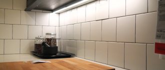
When you might need it
The reason for connecting LED strip fragments is usually the same. Typically, lighting strips are sold in rolls of up to 5 m, and this length is not always enough for all areas of the premises. For example, you want to wrap a ribbon around the perimeter of a suspended ceiling for beauty. Will 5 meters be enough? Of course not. The same applies to the decor of the facades of shops, banks, and beauty salons. So the LED filaments have to be extended by connecting individual fragments.
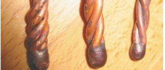
Rotate 90 degrees by soldering.
What and where to solder in the LED strip
LED strip (LED) is a light-emitting electrical structure in the form of a flexible printed circuit board (tape) with light sources evenly applied to it - light-emitting diodes (LED) and electric current limiters - resistors (resistors).
When is soldering needed? Example: when contour lighting a ceiling, it is necessary to lay the SDL at a right angle. Despite the flexibility of the board, an ideal right angle can only be achieved by connecting its two parts. Therefore, it is cut into 2 parts in a place specially designated for this purpose, so as not to break the connection diagram of the crystals.
SDL cut location
After this, work on connecting the SDL begins. The complexity of the soldering process depends on the type (single-color, multi-color), type (open, sealed) of the tape, the number of current-carrying paths, and the use of additional devices.
Complex connection diagrams
Connecting multiple tapes
If several tapes are connected, and the power supply does not provide sufficient power, then each of them can be used with its own unit if it has the necessary parameters.
Connecting RGB strip
When connecting an RGB LED strip, an additional device is used - a controller. With its help, colors are controlled, and the intensity of illumination of the diodes depends on it. The difference from single-color tapes is that four wires are used for connection: one of them is common, and the other three wires are used to control colors. When connecting, soldering or special connectors are used.
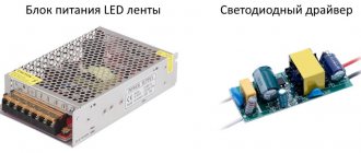
Connecting to the computer's power supply
The PC power supply has a 12V power rail that is suitable for LED modules. If you have an ATX unit, you cannot start the device immediately by plugging it into a power outlet. To do this, you must first short-circuit the green and black wires on the main connector.
Then the molex connector is cut off or a female molex connector is used, and tape is soldered to its wires. The result is a collapsible structure. To connect a very powerful lighting device, it is recommended to combine several yellow wires to reduce voltage drop.
It is not recommended to use a computer power supply without load.
How to solder together
It is possible to solder two sections of tape together (to build up) in two ways:
- Using connecting wires. Each line connects equivalent contacts of two boards (plus with plus, minus with minus).
- Overlapping connection. The connection occurs by overlapping sections on top of each other and soldering them at the contact pads.
- If the SDL is long, it is connected in parallel to the common bus using connecting cables.
Unit power
In order for the devices to shine at full power, and the unit to be guaranteed to cope with the loads, when purchasing it you will need to make simple calculations. In most cases, the marking of the tapes indicates the power consumption per meter of the product. Therefore, this value should be multiplied by the required length and add 20% for the margin.
Control panel for multi-color ribbon Source vahrushi.el43.ru
For example, it is necessary to install a backlight with a total length of 13 meters, while the rated power consumption of the selected strip is 9 watts per meter of length. Multiply 13 by 9 and get 117 watts. 20% of this value equals 23.4 watts. Plus 117 and we see that for such illumination you will need a unit with a power of about 140.4 watts.
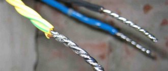
Soldering wires to tape
- Clean the ends of the connecting wires using a utility knife or stripper. Tighten the exposed (bare) parts slightly.
Stripped connecting wire
- Tin open ends. Solder is taken to the end of the soldering iron. The end of the cable is dipped in rosin and then solder is applied with a soldering iron. For uniform coverage, the process is repeated 3-4 times.
The process of tying up ends
The length of the cable (up to 2-3 mm) is selected so that its bare ends lie exactly in the “cups” of the contact group. An end that is too long can cause the plus and minus contacts to short out.
- Tin the contact pads of the LED strip:
- Use the end of a toothpick to apply flux to the contact pads.
Applying flux to contact pads (nickels)
- Using a heated soldering iron, apply solder to the contacts by briefly pressing (up to 2 seconds). The maximum contact time between the SDL and the soldering iron is 5 seconds. It is important not to short-circuit the contacts when applying solder.
Applying solder to pads
- Solder the connecting wire to the SDL. Its end is applied to the contact pad of the board. Then, with a short, gentle pressure, solder is applied from above with the tip of a soldering iron.
Due to the high temperature, the tin melts and the wire sinks into the contact “cup,” thereby guaranteeing a reliable connection protected from oxide.
Solder the connecting wire to the SDL
- Solder the second wire in the same way.
Solder the second connecting wire to the SDL
Results
So, we have looked at various options and methods for connecting the LED strip to the power supply and control devices. Using the diagrams, explanations for them and our recommendations, you can independently install all the equipment. Of course, if you do not understand certain nuances, you can ask your questions in the comments to the article. We will definitely answer them in detail and try to help you throughout the entire installation process. Let's go together all the way from purchasing components to clicking the switch and turning on the tape.
Overlapping connection without wires
- Tin the contacts of one of the tapes on both sides:
- remove the required distance (up to 2-3 cm) of the adhesive base from the back of the board;
- clean the back surface of glue;
- tin the contact pads on the working and opposite sides of the board.
The process of sealing contacts when connecting a board with an overlap
- tin the contacts of the second tape on the working side.
- Place the “back contacts” of the first tape on the contacts of the second tape located on the work surface.
The process of connecting two boards with an overlap (step 1)
- The upper contacts of the first tape, which should be on top of the structure, are heated with a soldering iron. The holding time of the soldering iron in this case is longer (4-5 seconds), because it is necessary to melt both boards together.
The process of connecting two boards with an overlap (step 2)
This connection is not reliable. It is better to use connecting cables.
Lighting brightness
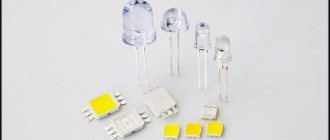
LEDs have different brightnesses, and the brightness level can be determined by digital markings. The numbers allow you to determine the dimensions of the diodes, as well as the power of the generated light flux. Main diode models:
- 3528. LEDs of this class have average brightness, and one lamp emits 4-5 lumens of luminous flux. Such diodes can be used to illuminate furniture, floors, walls, ceilings, and decorative elements of the house. Another application option is illumination of a multi-tiered ceiling based on plasterboard.
- 5050/5055/5060. It is a class of similar LEDs capable of generating radiation in the range of 12-15 lumens. Such systems are suitable for lighting small and medium-sized rooms, as well as auxiliary lighting for furniture, ceilings, and decorative elements.
- 2835. Systems of this type generate a high level of luminous flux in the range of 25-28 lumens. Such LEDs can be used to create complete lighting in a home, office, small or medium-sized public institutions. Their use for auxiliary lighting is inappropriate.
- 5630/5730. It is a class of similar LEDs capable of generating powerful light radiation at a level of 60-75 lumens. Devices of this type are used to illuminate streets and large premises. Another popular area of application for 5630/5730 diodes is the creation of outdoor advertising.
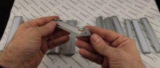
Soldering silicone coated tape
- Stripping the tape from silicone insulation.
Using a utility knife, cut the silicone across the board at a short distance from the contact group. The cut should not be deep so as not to damage the current-carrying path.
Break the cut area and remove a piece of silicone.
The process of cleaning SDL from silicone
- Consistently repeat the process of “soldering wires to tape” or “overlapping connection without wires.”
- If the SDL protection level requires a silicone coating, it is necessary to restore the protection using heat-shrinkable tubing, silicone or glue.
Soldering wires at an angle
This scheme is used when it is necessary to connect sections of SDL in parallel to a common supply bus.
Parallel connection of SDL sections
Figure 104 - example of parallel connection of SDL sections
When connecting the cables in series to the ends of the board module and then bending them towards the bus, the distance between the sections of the tapes increases, which will not look aesthetically pleasing during its operation.
Conventional diagram of parallel connection of SDL sections when connecting cable lines in series to the ends of the module
To do this, solder the wires at an angle:
- The wire is soldered at right angles to the contact, which is located closer to the power bus.
Solder at an angle (step 1)
- When connecting the second cable in the same way, the current-carrying parts overlap, which can lead to the contacts closing together.
Solder at an angle (wrong location)
To avoid a short circuit, the second wire is soldered to a contact that was located on the board earlier and belongs to the same group of diodes.
Solder at an angle (step 2)
LED RGB strip
The peculiarity of RGB tape is the contacts located close to each other. When carrying out work on wiring contacts, care must be taken not to close them together with tin tracks due to the short distance.
To do this, use the following methods to reduce the area of the tip (tip) of a soldering iron:
- Sharpen the existing tip using a file. The process is labor-intensive and not rational, because the tip will be damaged and may not be suitable for other jobs.
- Self-production of a tip from a copper cable core with a cross-section of 1-2 mm. Such a tip is attached to the main structure with a bolted connection or a collet connector, depending on the modification of the soldering iron.
A small area of the core will allow you to apply tin more accurately and accurately, but it can lead to rapid overheating of the device.
- Purchase ready-made tips of the required shape and cross-section. If you frequently solder SDLs, this is the most profitable method.
RGB LED strip contact strip
For parallel connection of SDL, each cable is also soldered at an angle to one contact on the module.
Use via computer
Duralight can be used to illuminate the workplace. In this case, you don’t have to connect it to a power outlet or through a switch and use the device without a power supply; just connect the LED strip directly to the computer. This can be done in several ways.
Via USB connector
Most standard duralights require a supply voltage of 12 V or 24 V, while the USB port has a voltage of 5 V with a permissible current of up to 500 mA.
The easiest option in this case is to purchase a non-standard 5-volt duralight with a connector for a USB connection (for example, made in China); it can be connected to any device equipped with a USB port.
The option using USB is the only possible one for connecting to a laptop; there are other less labor-intensive methods for powering it from the system unit of a desktop computer.
Via one of the molex connectors
There are several of these connectors in the PC; they are located under the side cover of the system unit and have 4 contacts with insulation color coding - yellow (+12 V), 2 black (GND) and red (+5 V). To connect the LED strip, yellow and 1 of the black wires are used. To make the connection detachable, you can use a MOLEX-SATA adapter. To connect duralight, the following steps are required.
- Turn off the computer and remove the side cover of the system unit.
- Remove the SATA plug from the adapter; it will not be needed.
- Solder a duralight contact with a “-” sign to the free ends of 1 of the black wires, and a contact with a “+” sign to the yellow one.
- Cut or insulate the remaining black and red pins.
- Find an unused molex connector and connect it to the adapter to test turn on the duralight.
Direct to motherboard
Some PC models allow you to connect the LED strip to the corresponding connector on the motherboard, but not every device has it. The easiest and most convenient way to connect duralight to the motherboard is to purchase a ready-made installation kit, which includes an RGB strip and all installation components.
Common mistakes when soldering LED strips
- Heating the soldering iron above 250 - 300 0C.
High temperatures will cause the contacts to overheat and peel off from the board. You can determine the high temperature of a soldering iron tip in the absence of a regulator by the following signs:
- smoke coming from a soldering iron;
- when the tip is dipped into rosin/flux, it boils;
- poor solder connection to the tip;
- black carbon deposits on the soldering iron tip;
- the surface of the solder on the soldering iron tip is loose and matte (there should be a silvery sheen).
- Use of soldering acid and/or active flux
One of the negative properties of acid is the erosion of the area around the contact group.
Active flux has a long reaction (interaction with metal occurs even after soldering), and therefore requires rinsing off.
This has a negative effect on the contact group and can lead to disruption of its conductive properties.
- Use of low-quality LED strips.
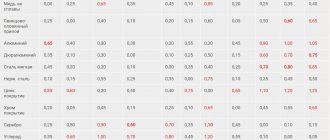
Often, counterfeit SDLs use non-copper alloys that are not soldered.
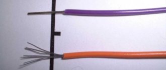
- The use of rigid multi-core cables that do not have reliable solder fixation.
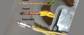
Connection methods: soldered, connector and clips
- Soldering involves using solder and heating it under the high temperature of a soldering iron to firmly connect the contacts to each other or to the cable.
Soldering is the most reliable method, and the tin-lead composition protects exposed conductive parts from oxidation and overheating.
Its disadvantage is its low mechanical strength; for this purpose, the solder area is protected with heat-shrinkable tubing or silicone.
- Clips. SDL sections are connected sequentially into only one line. The device consists of a small box with metal conductive clamps, which are installed to equivalent contacts of the modules and clamp them together.
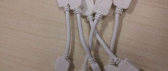
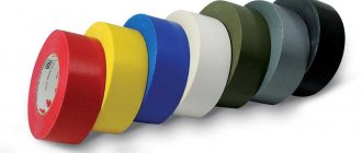
- A connector is a device designed to connect sections of SDL to each other without the use of soldering.
Connector example
Connectors can be with or without connecting wires (for overlapping connections), various shapes of connectors (T-shaped, angular, straight).
Types of connectors
Controller (dimmer)
Controller (dimmer)
A controller (dimmer) is an auxiliary device in the form of a box that is built into the lighting strip circuit. Its main function is to control brightness, color, diode attenuation and other lighting parameters. In monochrome systems you don’t have to install a dimmer, but in the case of RGB devices you can’t do without it. According to the control method, dimers are of three types:
- Software controlled. Such dimmers control the operation of the lighting device according to a given program, which either cannot be changed, or can be changed, but within certain limits (for example, using a button you can select one program from a list). The main advantage of such dimmers is their low price.
- Push-button digital . These dimmers have a small dial and buttons that can be used to control the system within certain limits. For example, you can increase the brightness or set the lighting color. Such devices are more expensive, but they also have better functionality.
- Wireless. Such dimmers consist of two elements - a control block box and a control panel. The box is built into the circuit, and the remote control allows you to control the device remotely. Using the remote control, you can set the brightness, color, tints, smoothness of fading and other lighting parameters.
Connector or solder?
- The connector is convenient in the following cases:
- when soldering is not possible. For example, when assembling SDL directly under the ceiling. Soldering by weight is a dangerous activity, which can lead to burns as a result of dripping solder and damage (burn-through) of the ceiling covering.
- When changing design. The SDL is easily disassembled into sections and assembled according to the required sketch, thanks to the variety of connectors.
- When working with moisture-proof tape, it is recommended to use soldering, because it provides complete protection and insulation from moisture.
- Related Posts
- Properties and principle of operation of a salt lamp
- Types and characteristics of induction lamps, advantages and disadvantages
- Let's talk about different types of pool lighting and its beautiful implementation
Discussion: 2 comments
- Oleg:
Thank you for the information provided. By the way, who knows where is the best place to buy a New Year's garland? With just over a month left until the New Year, it’s time to think about decorations in the house