What is SIP
First you need to understand how SIP works, what brands there are and how they differ. The abbreviated name SIP stands for Self-Supporting Insulated Wire.
Although for many, wire and cable remain synonymous. And SIP is also often called a cable. Apparently due to the fact that it is heavy and thick)
The main difference is that a wire is a metal conductor that can be solid or stranded, bare or insulated. A cable is a set of wires that have separate insulation, which are combined together and covered with a common insulating sheath. I wrote more about power cables here.
The design of the SIP wire includes phase conductors consisting of aluminum or aluminum alloys and a neutral conductor. The neutral conductor can be made entirely of aluminum alloy or have a steel core inside, coated on the outside with an aluminum alloy. Also, the wire design may contain additional cores designed to power street lighting networks.
It should be immediately noted that SIPs with main copper cores are not produced.
According to the current GOST 31946-2012, the following brands of SIPs are distinguished, intended for networks with a voltage of 380 V:
- SIP-1 has insulated phase conductors, the supporting zero conductor has no insulation.
- SIP-2 has insulated phase and neutral conductors. The zero core is the carrier. Designed mainly for installation on overhead lines (OHL) and for organizing linear branches from them.
- SIP-3 with additional protective insulation is designed for networks from 6 to 35 kV.
- SIP-4 also has insulated phase and neutral conductors, but structurally does not have a load-bearing element. The load is distributed evenly between all cores. Such wires cannot be connected to each other in overhead line spans. It is allowed to connect them only on supports.
- SIP-5 mainly differs from SIP-4 in that it is capable of operating at low temperatures. This GOST does not talk about it.
For “domestic” use (connecting private houses), in most cases, SIP-4 wire is used. Its minimum cross-section is 16 mm2, the number of cores is 2 (for single-phase connection) and 4 for three-phase.
It should be noted that flame retardant wires must be used for inputs into the building and for laying along the walls. Such wires are marked with the letter “n”. For example, SIPn-4. It is SIP with the letter “n” that is recommended in the specified GOST (Table 9a) for branching from overhead lines and for laying along the walls of buildings and structures.
I will add that from the point of view of conductivity for SIP, as well as for other types of cables and wires, the important parameter is the resistance of the core, and not its diameter or cross-section (which is essentially the same thing). I have spoken about this more than once in my articles and comments, but still most readers, when checking a core, take a caliper rather than a milliohmmeter. The maximum electrical resistance of SIP wire cores is given in GOST 31946-2012, Table 3.
Selecting a single-phase electric meter
When choosing an electricity meter, we were guided by the following criteria:
- single-phase;
- rated (maximum) current;
- fastening method;
- operating principle of the device.
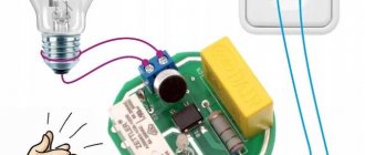
Since we live in a modern world, we therefore wanted to have a modern electricity meter with an electronic display. In the store we were offered a single-phase multi-tariff meter Energomera CE 102
Single-phase multi-tariff meter Energomera CE 102
It fully meets our selection criteria, here is a list of its characteristics:
- Accuracy class 1
- Number of tariffs 4
- Measuring network frequency, Hz 50±2.5
- Rated voltage, V 230
- Basic (maximum) current, A 5 (60); 10 (100)
- Starting current, mA 10; 20
- Parallel circuit power consumption, no more, V*A (W) 9 (0.8)
- Total power consumption of the series circuit, no more, V*A 0.1
- Operating temperature range, °C from minus 45 to plus 70
Connection diagram for Energomera CE 102 counter
Meter connection diagram
Pros and cons of SIP
Advantages of SIP
The use of SIP wire allows you to eliminate several negative reasons inherent in overhead lines with bare wires.
Advantages of SIP:
- It is impossible for a short circuit to occur due to fallen branches or other objects, since the wires are insulated. This also indicates a low probability of fires.
- High mechanical strength of SIP, as a result of which its breakage is unlikely even when heavy objects fall on it.
- Possibility of reducing the dimensions of overhead lines and reducing the distance to building elements.
- Less electricity losses during transmission (we are talking about leaks to the ground, for example, through tree branches).
- Impossibility of stealing electricity by attack.
- Long service life and lower costs during operation of overhead lines.
- When constructing overhead lines, it is not necessary to install crossarms on supports.
- It is possible to lay SIPs along the facades and walls of buildings, but only at a certain distance; for this purpose, SIP facade fastening SF60 is used.
- Possibility of performing some types of work on overhead lines without removing voltage.
The fact that the SIP is insulated is a big plus. This saves not only from short circuits and theft of electricity, but also from electric shock. And not only people, but also wild animals. This photo was sent to me by a reader from the Belarusian outback:
Stork on a pole with SIP
Busel feels great even in pouring rain - thanks to the SIP insulation!
A hint for marketers - SIP can be positioned as an Eco-wire that saves the environment, this will double the price!
Disadvantages of SIP
The disadvantages include the need to train personnel who perform work on self-supporting insulated wires, as well as the cost of overhead lines, which is higher than that of lines made with bare aluminum wire.
One more drawback can be identified, which is a consequence of the advantages of SIP. Since the likelihood of interruptions in power supply due to blocked wires is reduced to zero, this means that overhead line routes are cleared less frequently than for lines with bare wires.
If wood grows into uninsulated wires, it will block them and cause a short circuit. In order to apply voltage, the tree or branches must be cut down and the wires pulled over.
In the case of SIP, everything is not so simple. Trees grow quickly and reach the SIP wires. What do you think is happening with the wires? The insulation on the wires does not wear out immediately, but it does fray. This means that by approaching such a tree on a damp day, you can feel all the delights of the effects of electric current on the human body.
Specifics of gluing cable channel
Gluing is as easy as shelling pears, but you need to take into account that you need to completely forget about dismantling the glued box. You can’t just tear it off, only together with a piece of the wall or its decoration. True, installation will require a minimum of effort and time; the only consumables are glue, for example, “liquid nails.”
The algorithm is as follows:
- We apply the adhesive composition in a kind of zigzag with a step between the “tops” equal to approximately 1.5 times the width of the box;
- We apply the base treated with glue to the wall, but do not fix it on it, but remove it to the side;
- wait until the remaining adhesive trace on the wall thickens;
- install the channel in place and press firmly;
- again we wait for the glue to harden.
For your own peace of mind and increased reliability, you can supplement the adhesive fastening with nails driven along the central axis of the box in increments of 50-60 cm.
Only after hardening will it be possible to begin laying the cable, which for convenience needs to be fixed in the channel. For permanent fixation, special plastic holders are useful. Thrifty craftsmen can use available devices: pieces of the cover or the cable channel itself. Temporary fixtures will undoubtedly need to be removed before attaching the cover.
Why you can’t bring SIP into your home
First, the official information. According to GOST 31946-2012, according to which all SIP wire is produced in our country, “3.1 self-supporting insulated wire:
Stranded wire for
overhead power lines (...)”.
The exception, as I said, is only for the wire with the letter “n” - it can be laid along the walls of buildings from the outside. And even then – at a certain distance from the surface. The additional letter “n” in the marking indicates the fireproof design of the SIP. The polyethylene insulation of such wires is self-extinguishing and does not support combustion. However, such a wire cannot be brought into the house either.
A special feature of SIP insulation is that its insulation is designed for outdoor use. This means that it is resistant to sunlight. Cable insulation for indoor wiring must have a very low flammability, and resistance to sunlight is not important here.
Since SIP insulation is made of polyethylene, which burns with the formation of burning molten drops that set fire to everything around, the limitations on the scope of SIP use are understandable.
Some readers may have a question: why does it have to light up? After all, no one will deliberately set it on fire in the house. Here we remember the beginning of the article. Where it was said that a fire can occur at any time due to improper connection.
The main cores of SIP are made of aluminum or its alloys. As you know, aluminum is a soft metal and the contact connection tends to weaken over time. If the contact is not tightened in time, it will heat up. When heated, the contact resistance will increase, which will lead to even greater heating and cause arcing of the contacts. The problem grows like an avalanche: more heating - worse contact - more heating, etc. Aluminum “flows” inside the terminal and its tightening becomes weak.
The situation is complicated by the fact that the aluminum wire and the terminal material of the machine or meter (copper-brass alloy) have different temperature expansion coefficients.
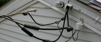
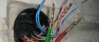
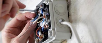
This means that a situation may arise when the contact deteriorates and heats up so much that the SIP insulation begins to melt or catch fire. As an example, I will give a few photographs. Three-phase input to a circuit breaker in an electrical panel:
The result of incorrect connection of the SIP to the terminals of the circuit breaker. The counter also got it.
As you can see in the photo, due to poor contact and probably considerable load, the wire got hot, which led to the melting of the insulation, which began to flow down the body.
SIP insulation melted due to heating and flowed down
In the event of a fire, such insulation, continuing to flow, could possibly set fire to the entire panel. The photo clearly shows that the insulation was severely melted, and the owner decided to “fix” it with electrical tape.
SIP wires - the insulation melted due to heating
That is, the problem did not arise suddenly, they tried to eliminate it.
It is not the effect that needs to be eliminated, but the cause. And the reason here is an incorrect connection. One might say that the technology has not been followed. But more on that below.
When heated, a short circuit occurred and two wires burned out. One core remained intact (phase on pole 2). And two wires are soldered together and at the place of soldering you can see a burnt-out insulation (hole). There was little time left before the short circuit. The worst thing about this situation is that in the event of a fire, turning off the power supply would be problematic.
The same electrical panel in which the input circuit breaker was promptly replaced:
Reconnection of SIP and installation of a new input machine
Moreover, the ends of the SIP are again connected in the same way. This means the problem may repeat itself. Plus - it should be noted that the rating of the installed input circuit breaker is lower (it was 63 - now 40 A), which means that the maximum current of the SIP will be lower. But the question is: how long will it last? – remains relevant.
While we're on the subject, a couple more mistakes in this closet. After the introductory machine there is a nominal value of 63 A. It is unlikely that choosing such a large nominal value is advisable and safe. By the way, phase burnout is not as scary as zero burnout. If there is poor contact at the points 4th pole of the machine - 4th pair of meter contacts - bus N, not only a fire is possible, but also damage to single-phase household appliances. If you do not agree with me, read the articles What is a zero break in a three-phase and single-phase network and Three-phase electrical panel diagram - I answer the reader’s questions. I also described how to connect a PEN wire to the metering panel in the article Electrician in the mountains of Georgia. Well, there is no grounding, from the word “at all”.
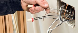
Moreover, keeping in mind the possibility of SIP fire, it cannot be installed on flammable surfaces, even outdoors. Here is a photo sent by a reader. Here the “street” is the wall of a wooden country house:
SIP is turned on automatically on the external wall of a wooden house
The outgoing cable is not yet connected. I advised the reader to place a metal or asbestos substrate under the box, and take care of the quality of connecting the SIP to the terminals of the machine, which will be discussed below.
Material
Before installation, you must purchase all the material, namely:
- SIP 4*16 or SIP 2*16 (depending on 220V or 380V input)
- Bandage tape SOT37 ~ 2.5-3m (for attaching the hook to the support)
- SOT36 clamp – 2 pcs (tape fixation)
- Bandage hook SOT39 or SOT29 – 1 piece
- Wall hook SOT28 or SOT76 – 1 piece and mounting anchor bolts for it
- Anchor clamp SO80 or SO158 – 2 pcs.
- Piercing clamps SLIP12.1 – 8 pcs (for 380V input) and 4 pcs (for 220V input)
The brands of materials from the manufacturer ENSTO are indicated here; in your case, the specification (SLIP, SO, SOT, etc.) may not be the same, but the names themselves (piercing clamp, anchor clamp, clamp) should be the same.
Before starting work, it will be necessary to take certain measurements. The distance from the support to the facade of the house where the wall hook will be located should be no more than 25 m. Otherwise, you will have to install an additional support support.
Choose SIP depending on what input you will be installing into the house - 220V or 380V. When purchasing SIP, it is better to make some reserve in footage for all sorts of unforeseen situations. Basically, the 4*16 SIP brand is used for entering the house.
It is important to make one note
clamp for connecting to bare wires
Two hooks are installed on the support and facade of the house. It is between them that the SIP is stretched. Its fixation is carried out with anchor tension clamps.
Source - Kabel.RF
How to install SIP correctly
As for how to properly install SIP to a house, you can find a lot of varied information on the Internet, which is sometimes quite contradictory. What is the best way to proceed? Where to go for help? Of course, contact the manufacturer!
We find the website of the Niled company, which modestly calls itself “the main initiator of the implementation of self-supporting insulation systems in the Russian Federation.” Here you can find technological maps for carrying out various works on lines performed by self-supporting insulated wires, which were developed together with PJSC Rosseti.
We find album No. 1, cards No. 5, No. 6. The maps describe the technology of work on connecting the input to the house from the main VLI - an isolated overhead line, that is, SIP. Specially trained personnel who have the appropriate materials and tools, as well as protective equipment, must connect the SIP from the overhead line to the house. That is, the question of choosing the best method is removed by itself. You contact the energy supply company, pay the specified amount of banknotes and wait for the team to arrive.
Connecting SIP to the house. It was smooth on paper
But it's only smooth on paper. As in any business, there are many subtleties, and connection to the line must be entrusted to a team from the energy supply organization.
Unauthorized connection of a home input to an overhead line can easily result in several months of treatment spent in a hospital bed. There is nothing to do on the support without using the appropriate tools and protective equipment. Also, you need to remember that you can be fined a hefty sum for unauthorized connection.
But even if the person reading these lines is not an electrician, it is important to navigate them. For example, what are the editing errors, who can tell?
SIP 2x16 mounted on the wall of a private house
We need to touch on one more topic - where is the equipment of the energy supply organization, and where is the subscriber equipment? To answer the question, you will have to look into the agreement concluded with the energy supply organization - the guaranteeing supplier of electricity.
The contract must indicate in black and white the boundary of the balance sheet. Formally, this is the boundary of the site, but in the Act for the delimitation of balance sheet ownership, this boundary usually runs along the accounting board. Tell us in the comments where this border is for you - at the place where the SIP is connected to the input circuit breaker, at the terminals of the meter, or at the terminals of the cable going to the house?
There is good news for new subscribers: from July 1, 2022, in accordance with Federal Law No. 522 - Federal Law, the responsibility for installation, replacement, verification, replacement and operation of electricity meters falls entirely on the electricity supplier. But as usual, there are often problems with this locally. For example, they may say “there are no meters, they will bring them in half a year.” And what? People have to agree to bet at their own expense.
In this article we will consider only the issue of electrical connection of SIP from the consumer side.
Safety precautions
You cannot carry out any electrical work:
- in high humidity, fog or rain;
- in the dark;
- wearing clothes with short or rolled up sleeves;
- using a “walnut” connection when connecting on the facade;
- if any damage to the VLI is found on the support.
Step ladders should be used with extreme caution. Their length cannot exceed 5 meters, and the angle between the pillar and the stairs should be 60-750
In any case, pulling wires while standing on a ladder is strictly prohibited.
For installation you will need:
- turn off all power supply circuit breakers so that the SIP is without load;
- overalls with thermal protection;
- technological maps (all work is carried out only according to these documents);
- protective equipment regulated by technological maps;
- insulate with protective covers wires that may accidentally come into contact with a person.
The work is carried out by 2 electricians: one climbs the pole, and the second carries out installation on the facade. Installers should have a first aid kit. Lifting is carried out from the side opposite to the location of the SIP. This is necessary so that the electrician does not fall if the wire breaks.
First, you must obtain permission to carry out work from the owners of the VLI. It is necessary to check the stability of the pole on which the VLI is located. If we are talking about a wooden support, then it is necessary to assess the degree of decay. For this purpose, a special device is used - POZD. The installation diagram is shown in the figure.
The SIP is stretched between two pillars on the facade and the support, and fixation occurs with anchor tension bolts
It is important that the fastening is carried out correctly
First, the electrician climbs up the pole and mounts the hook using staples and banding tape. When attaching a wire to a wooden pole, a through hook is required, which is installed without a banding tape. Now the wire is secured in an anchor clamp, which is fixed with a bracket. You need to leave about half a meter of wire to make connecting the SIP more convenient.
Now the second electrician is working on the facade. It stretches the wire and determines a convenient clamping location at the end of the cable. The SIP is placed in a clamp and secured to an anchor. Next, the wire is pulled along the facade to the entry point.
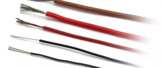
Which wire in SIP is phase and which is zero?
I see that this question comes up quite often, but it is actually very simple. It is enough to refer to GOST for SIP, which clearly describes its colors.
GOST 31946-2012 section 5.2.7.2: The main conductors of self-supporting insulated wires must have a distinctive marking in the form of longitudinally pressed relief strips on the insulation (...). An insulated zero load-bearing core should not have a distinctive marking. The distinctive designation can also be made in the form of colored longitudinal stripes with a width of at least 1 mm. The color of the stripes should be contrasting with black.
SIP connection color – neutral – no designation
It turns out that the phase conductors always have a longitudinal colored line, the zero (neutral) wire does not have any line. And even if there is a blue stripe on the wire, this is a phase, and not neutral, as it might seem!
But. SIP is also produced, in which all conductors are color-coded. Including blue ones. In this case, GOST R 50462-2009 , which establishes general rules for the use of certain colors and alphanumeric designations to identify conductors. There in paragraph 5.2.2 it is said that “ The neutral and middle conductors should be identified in blue. The color blue shall not be used to identify any conductor other than the grounded line conductor
(in this case, neutrals)
“
At the same time, despite the clear presentation of this issue in GOST, you must always use the rule: “Trust, but verify!” Otherwise, it will be like one of my readers - he made a metering board, connected the “blue” SIP conductor through the machine to the meter, and connected the neutral conductor directly to the GZSh, dividing it into N and PE (TN-CS grounding system). A local electrician “with 40 years of experience,” who was officially called to make the connection, without warning anyone, climbed onto the pole to connect the SIP. Having rolled off the pole after the short circuit with bulging eyes (the introductory machine was turned off!), he began to learn the materiel.
Connecting SIP to overhead lines on a support
Input panel
Now all that remains is to assemble the introductory panel, look:
Installation of an electricity meter in the input panel
So our input circuit breaker, which protects the input cable, is located on the pediment, and so that when distinguishing electricity each time we do not have to run to the second floor, it was decided to install another circuit breaker in the panel.
Installation of an input machine on a DIN rail
According to the diagram above, we connect the electricity meter to the circuit breaker
Connecting phase meter a to the machine
Connecting a zero meter to the machine
Connecting the zero output from the counter to the zero bus
We install a circuit breaker on the DIN rail to protect the socket and connect the phase and meter output of Energomer CE 102
Connecting the phase wire output from the meter
Now we cover everything with protective plates from the input panel kit.
Input panel assembly
Examples of connecting SIP to a house
Well, the whole connection process is shown in Dmitry’s video, Electrician’s Notes channel:
The conclusion of the article is simple. Long-term trouble-free operation is guaranteed only if the SIP is correctly connected. But such a connection is the most complex and responsible in the entire house, and requires careful preparation and high qualifications.
I ask readers to vote - which method of connecting SIP do you use?
Thank you all for your attention, I look forward to questions and criticism in the comments!
Country affairs
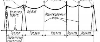
If you still haven’t decided which method of laying cables in the ground to choose, we recommend following our simple tips. There are a lot of ways to accomplish this task. Professionals still cannot decide which method is better - ground or air.
We suggest that you give preference to the earthly method. It's easy to explain. Usually the distance from the pole to the house is large and most likely you will want to install outdoor type lighting. In these cases, the earthly cable laying method is ideal.
To lay an electrical cable underground, follow these simple instructions. First of all, you need to purchase an electrical cable for laying in the ground at your dacha.
After this, you can start choosing the most suitable cable route. In this case, certain features should be taken into account. The cable must be placed 1 m from massive trees. Please take this into account.
Laying a cable is not as simple a process as it seems at first glance. You need to make sure that the wires do not get tangled, and you should not place it in places with high load.
You should start by creating simple markings, and then move on to excavations. The trench where the cable will be located should be no narrower than 70 cm.
As for the depth, cable lines up to 20 kV should be laid to a depth of 0.7 m, up to 35 kV - 1 m, with streets and squares - 1 m, regardless of voltage, oil-filled cable lines should be laid to a depth of 1. 5m.
Once you have created the required trench, you can begin filtering it. In other words, remove all stones and other objects. The next step is to create the pillow. It is better to make it from a material such as sand.
The depth of the pillow should be approximately 10 cm. We recommend that you give preference to the ABVg cable. This is a universal option. To ensure cable protection, we recommend that you use asbestos cement pipes. The cable should be laid freely so that unnecessary pressure is not placed on it. We advise you to create a separate cable layout plan.
Important! Lightning rod in a private house, here!
After all the preparatory steps, you can start filling the cable. This should be done with sand. Its layer must be at least 10cm. The final stage will be laying the warning tape. The final stage will be filling the trench with earth.
Laying electrical cables underground
The laying of electrical cables underground must be carried out in compliance with all technical standards. You should know that it is better to plan the route initially; its radius should have clearly defined dimensions, which should not exceed the permissible norm for each individual cable.
You must take into account the presence of distribution couplings. The cable must be delivered on cable drums, which in turn are delivered on special vehicles.
You should note that the drums should be unloaded very carefully. We recommend that you consult a specialist if you doubt your capabilities. Laying cables underground requires careful preparation and the necessary knowledge.
Laying an electrical cable in the ground
Pay attention to cable selection. Successful installation of an electrical cable in the ground depends primarily on its quality
We recommend that you give preference to copper cables.
They must be armored. The cable that you must purchase must necessarily have technical documentation, which will indicate exactly what it is intended for.
In our case, this is a gasket in the ground. The cable should only be laid from a special drum. You must take this into account.
The cable itself must also have some protection. Let it be a steel braid. Such a cable will cost more, but you will not doubt its quality for a minute.
Take into account all the recommendations given, and you will successfully lay an electrical cable in the ground
Special attention should also be paid to safety precautions. Use special clothing and accurately carry out the necessary calculations
The cable must fit with a certain margin.
It is very important. Avoid cable tension
The margin should be approximately 2%. To correctly connect cable joints, use couplings. Clearly determine the distance between the coupling and the cable. It should be approximately 250 mm.
Installation errors
Common mistakes when installing SIP wires:
- Insufficient or excessive line tension, leading to increased load and premature failure of the load-bearing core or insulation. To ensure the required cable slack, use a dynamometer built into the hand winch.
- Repeated use of piercing clamps that does not allow the cable to be properly secured. SIP fasteners are disposable and must be disposed of if removed.
- Weak tightening of steel bands. Under the influence of temperature changes or wind, the brackets begin to slide along the surface of the pole. The defect can be easily eliminated by tightening the clamp with a special tool.
When laying wires, you should check the condition of the insulation: damage to the sheath leads to short circuits or electric shock to people. The cable is unwound on a surface without sharp objects. If tears are detected on the protective layer, the defective area is cut out. To join pieces of SIP, crimp sleeves are used, followed by insulation of the coupling. The use of artisanal connection methods (for example, twisting of cores) is strictly prohibited.