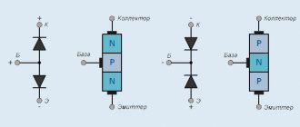
Design
An LED is a semiconductor element similar in design to a diode. When current passes through the LED, optical radiation visible to the eye is created. This part consists of:
- An anode through which a positive charge is applied.
- A cathode through which a negative charge is applied.
- Reflector of light fluxes.
- Emitting semiconductor chip or crystal.
- Glow diffuser.
This is the standard design for lamps of all shapes. To achieve brightness, manufacturers only increase the number of layers or the number of crystals. These values directly affect power.
Diagnostics of the LED in the flashlight
An LED flashlight, battery-powered or other types, is a fairly reliable device, but it is not immune to breakdowns. If, even after installing new batteries, the glow remains weak or completely absent, you need to check the functionality of the LEDs and their drivers.
Before diagnosing a flashlight, it would be a good idea to check the batteries (even if they have just been unpacked) on some known good device. This advice may seem trivial to some, but quite often, as practice has shown, the cause of “showdowns” with household electronics is defective batteries, which is the last thing the home craftsman realizes.
Checking the flashlight is carried out in the following sequence:
- Unscrew the cap or conical part at the front of the housing.
- We remove the LED module.
- There are two contact pads on the LED board, to which the red and black wires are connected. The red wire corresponds to the positive polarity (marked “+” on the board), and the black wire corresponds to the negative polarity (marked “-”). In accordance with the polarity, a voltage of 3–4 V (no more than 4.2 V!) should be briefly applied to the contacts. If the brightness of the LED has not changed, then it needs to be replaced. Otherwise (the LED lights up properly), the driver must be replaced.
- Replacing an LED is only possible if its board is attached to the LED module capsule with screws. If the board is mounted on hot-melt adhesive, replacement will be impractical; in this case, the entire module is replaced.
After unscrewing the board, unsolder the LED and then install a new one.
In flashlights, LEDs are installed on aluminum radiators. To ensure effective heat dissipation, a fresh coat of special heat-conducting paste, also called thermal paste, should be applied to the heatsink before installing a new LED. The old dried layer, even if quite thick, cannot be reused and must be removed.
The test of a separate LED and the simplicity of the tester’s design are clearly demonstrated in the following video from the largest supplier of electrical equipment in Russia.
Often, when one or another electronic device breaks down, we without hesitation take the victim to repair, where we are presented with a hefty bill. Meanwhile, the cause of the accident may simply be a failure of the LED, which can easily be replaced on your own.
Thus, the ability to check the performance of these elements, which are used quite widely today, will save money and reduce repair time to a minimum.
LED lamps are popular and have many advantages, but their complex design means that the location of the breakdown is not always obvious. Checking the LEDs for functionality, if they break down, allows you to determine the cause of the malfunction and decide the fate of the problematic device. Let's look at how you can find out the condition of lamps at home using a standard tester.
Varieties
LEDs are used in various technologies. At the moment there are 2 main types of these parts:
- Indicator or DIP. Refers to low-power LEDs. They operate at an alternating voltage of up to 3.5 volts, with a power of up to 0.06 W. Used as light indicators for various electronic equipment. These elements are used for surface mounting for lighting strips.
- Lighting or powerful, operate at voltages up to 12 volts, with a power of 2.6–3 watts. Used for lamps and spotlights.
Technologies do not stand still. To the lamps of the usual design, various varieties have been added, differing only in the chemical composition of the crystal.
- Filomentous. Lamps that produce a white glow due to coating with a phosphor composition. The power of this type of LED is increased by using 28 parallel-connected crystals.
- COB. Designed by bonding crystals on an aluminum stand. The brightness of the glow increases due to focusing by the phosphor coating.
- OLED. Similar to earlier types of LEDs. The brightness and angle of luminescence are increased due to the use of polymer materials for the manufacture of the light emitter.
- Fiber. Fully synthetic construction with the addition of phosphor and polymers.
The principle of operation of these light elements remains the same. Only the consumed voltage has changed, power and reliability have increased.
Checking an LED strip without a power supply
If there is no 220V AC voltage or power source nearby, the easiest way to check the tape is with an ordinary battery. Many people use a crown for this purpose.
However, due to insufficient output voltage, you will not be able to check the actual brightness of the LEDs. Therefore, it is better to use A23 finger-type elements, which immediately produce the 12V required in most cases.
They can be pulled from the car alarm remote control or from radio bells.
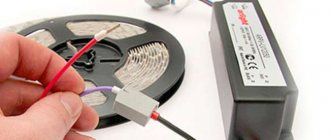
Using two thin wires, connect the plus and minus batteries to the corresponding contact spots on the tape.
With a short backlight length (up to 5m) and its low power, this will be enough for all the LEDs to light up. However, with the condition that the product is designed for an operating voltage of 12 volts.
If the tape is powerful and longer, then a battery assembly based on so-called magazines or containers may be needed.
With their help, you can assemble a full-fledged LED backlight, which will be in no way inferior to the usual one. At the same time, it has a bunch of advantages and applications.
Can't find the batteries you need, but are you a car enthusiast? Wonderful.
A car battery will do an excellent job of checking tapes of almost any power and length (in the context of organizing home lighting).
The only problem may arise in removing it from under the hood of the car.
As a last resort, if you have not yet installed the tape, you can always bring it to the car’s garage and check it directly there without removing the battery.
Principle of operation
The operating principle of any type of lamp is very simple. It can be described as the transition of positively charged particles from one semiconductor material to another. There are “holes” in the body of the second semiconductor, which, when filled with charged particles, release light photons. When current passes from one semiconductor to another, a difference in incoming and outgoing voltage is created. It is this difference that creates the luminous flux of the LED. Brightness is increased by a reflector that receives focused light and increases its brightness.
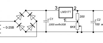
LED driver - what is it?
The direct translation of the word "driver" means "driver". Thus, the driver of any LED lamp performs the function of controlling the voltage supplied to the device and adjusting the lighting parameters.
Figure 1. LED driver.
LEDs are electrical devices capable of emitting light in a certain spectrum. In order for the device to work correctly, it is necessary to supply it with exclusively constant voltage with minimal ripple. The condition is especially relevant for high-power LEDs. Even minimal voltage drops can damage the device. A slight decrease in input voltage will instantly affect the light output parameters. Exceeding the set value leads to overheating of the crystal and its burnout without the possibility of recovery.
The driver functions as an input voltage stabilizer. It is this component that is responsible for maintaining the required current values and the correct operation of the light source. The use of high-quality drivers guarantees long and safe use of the device.
Power determination
The operating power of the LED is necessary for its correct connection to the operating circuit of any device. Many people are faced with the problem of how to find out the power of an LED without markings on the case or packaging. There are 2 ways to determine this parameter.
Visually
LEDs are produced in a variety of sizes and colors. By color and size you can find out the power of this part:
- Small infrared ones operate at a voltage of 20 mA, with a power of less than 2 Watts.
- Red ones have an operating voltage of up to 15 mA with a power of up to 1.7 W.
- Small yellow ones have a power of up to 2.2 W.
- Greens from 1.9 to 3.6 W.
- Blue from 2.5 to 3.6 W.
- Violet from 2.5 to 4 W.
- Large yellow ones operate from voltages up to 300 mA, have a power of 2.2 Watts, with radiator cooling.
- Large white or pink ones consume voltage up to 20 mA, with a power of up to 3.6 Watts.
You can determine the size of the LED using a regular caliper. Parts from 3 to 10 mm are considered small.
Multimeter
Determining the power of an LED with a multimeter is not difficult if you connect all the components according to the diagram. Next you will need:
- Find the cathode of the LED and connect one end of a 500 ohm resistor to it.
- Connect the “+” output from the power supply to the anode.
- Connect the negative from the power supply to the second end of the resistor.
This circuit will require a power supply with a voltage regulator. Further:
- Using the regulator, raise the voltage and measure it before and after the element being tested. It should be the same.
- Raise and measure the voltage again.
- Repeat adjusting and measuring voltage until a difference appears.
- At this point, you need to remember the last value in volts.
- Replace the 500 Ohm resistor with a similar element with a resistance of 10 Ohms.
- Raise the voltage to the calculated value.
- Switch the multimeter to ammeter mode.
- Measure the power.
This method does not require desoldering from the circuit if the LED is already connected to the circuit. The main thing is to correctly determine the polarity of the connection.
How to ring without soldering
To check the LED without desoldering, you need to analyze the device circuit. If there are no circuits parallel to the diode, you can ring it without desoldering it. Parallel circuits may influence the result.
You need to solder sharp steel needles onto the multimeter probes. The entire needle except the tip and probe must be insulated, for example, with heat-shrinkable tubing. Using a probe with a needle, pierce the layer of protective varnish until it comes into contact with the diode terminal on the case or the contact pad on the board. Measuring resistance in the forward and reverse directions shows the performance of the device. Direct resistance is tens to hundreds of Ohms. The opposite is hundreds of kiloohms or more.
Voltage detection
The voltage at which the LED operates normally is also an important parameter. Determining how many volts a part is designed for is very simple. To do this, you must first determine the polarity of the pins of the part. The new elements have a longer “+” leg. If the leads are the same length, you need to connect a multimeter to both legs in dial mode. If the correct polarity is observed, the LED should glow dimly. Reversing the polarity will not result in glow. The following is a description of how to determine the operating voltage:
- Connect a resistor of up to 510 Ohms to the “+” leg of the part.
- Connect the “-” terminal of the 12 volt power supply to the resistor output.
- Connect the “-” power supply to the second leg of the LED.
- Raise the voltage of the power supply to a certain point of bright light. Adjust the current supply gradually, without sudden jumps.
- All this time, measure the voltage with a voltmeter.
The voltage will increase until the transition inside the element opens. The opened junction will stop passing excess current. This value must be recorded. This is the operating voltage of the LED. If you continue to increase the voltage, the PN junction may not withstand it and burn out. If the polarity is not observed, the cathode will not pass electric current, which will cause loss of performance.
Method 1
A small fragment of PCB, literally a piece, but always with double-sided foil. A “spot” of solder must be applied to each so that in the future you can easily fix the wires and leads of the device for testing the LED. Probes from the multimeter, from which you should cut off (or unsolder, and then restore everything) the plug. The free ends need to be cleaned and tinned, that is, prepared for soldering. Paper clips – 2 pieces. They are given a shape that is clearly visible in the figure below. These will be the terminals of the device (analogous to plugs) that are connected to the multimeter. Although this is not the only option. Instead of paper clips, you can use flexible steel wire by cutting a couple of pieces of the required length.
LEDs.
The main thing is that these leads are slightly cushioned, then it will be much easier to connect them to the multimeter socket. Soldering acid. Using traditional pine flux is futile. The paper clips are made of steel, so the usual method for securely fixing them on PCB is of little use. Soldering iron. Power – at least 65 W. Trying to secure a paper clip to the board with a mounting tool (24, 36 W) is a waste of time. You will need to lay the melt in a relatively thick layer, and a low-power (miniature) soldering iron is useless in this case. Multimeter. These household appliances are available in several modifications. Their main difference is in functionality, that is, the ability to measure certain parameters of the circuit and parts.
It will be interesting➡ How to check the thyristor for performance?
You will need a multimeter that can test transistors. In principle, everything you need to make a simple device for checking an LED with a multimeter is always at hand. In the end it should look something like this. In order not to be confused with the polarity of connecting the probes to the LED, the terminals of the device should be slightly shifted from the center line. Then it’s easy to remember where the conditional “+” and “–” are. Checking the LED You need to insert the “contacts” of the device into the plug for testing Tr (anode terminal - to connector E, cathode - to C), put the multimeter switch in the “Transistor measurement” (hFE) position and attach the probes to the board at the points where they are soldered legs of the device (from the front or back, whichever is more convenient). If it is working properly and the polarity is correct (plus to the anode), it will begin to glow.
Cause of malfunction
LEDs operate at a specific voltage. At the output, the voltage of this part is significantly less. The reason for the malfunction of these elements is voltage surges. At a certain moment, a voltage exceeding the transition opening threshold is applied to the crystal, and the output voltage threshold increases. The LED burns out. You can visually identify a faulty element by the dark dot in the center. If it is impossible to visually determine the faulty element, in this case it is necessary to ring the part. Next, the process of testing an LED with a multimeter will be described.
Malfunctions and their verification
The most common tapes are powered by a mains voltage of 12 volts, which is safe for humans. So, to test the LED strip, we need: a strip, a power supply for it, a tester and a little time.
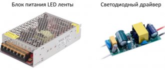
power unit
Checking any circuit is carried out in stages. It is recommended to start with the power source, since it primarily affects performance. There are two types of power supplies:
To check the power, set the tester to AC voltage measurement mode, make sure that 220 V is supplied (terminals 1 and 2), then switch to DC measurement mode and make sure that the required 12 V is received at the output (terminals 4 and 6).
Please note that a breakdown of the power supply most often means it needs to be replaced, as repairs can be much more expensive.
Checking the Tape
There are four types of possible faults:
Above we looked at what malfunctions can occur, then we will consider them in detail.
Doesn't burn completely
After checking the power supply, check the wires: they may be damaged and voltage is not supplied to the tape. Check the quality of the connection between the wire and the tape, it can be done:
The tape is flexible, but do not forget that it is based on a flexible printed circuit board, which has restrictions on bending; it can bend and burst . In this case, the board inside the tape may be damaged immediately after soldering, at the very beginning of the tape. Try applying voltage from the power supply to the following contacts. They are located a little further, where the tape is cut. Observe polarity (+,-). To do this, it is convenient to solder crocodiles onto the wires from the power supply and clamp needles in them.
Half doesn't light up
A special case of the problem described above. There may be a break in the printed circuit board circuit in the tape section. It is necessary to ring and remove the damaged section from the circuit. It can also be determined by checking the voltage supply to the cells sequentially one after another, to each contact. Make the connection carefully. Use connecting contactors or a soldering iron. Remove flux residues with alcohol.
The tape blinks or flickers
There may be several reasons:
Individual parts flash, flicker or do not light up
This is also a common problem. Occurs from damage to one of the LEDs connected in series, or to the resistance that is soldered in front of them.
Increased brightness of the tape is also a cause of this malfunction. In such cases, it is best to replace the damaged section of the tape. If you have good soldering iron skills, you can fix this problem yourself. We'll talk about this next.
Checking LEDs
Option 1
Checking the health of the LED with a multimeter is quite simple. This can be done directly on the board with a multimeter, without desoldering the LED itself. To check, you only need a multimeter turned on in diode testing mode. Before checking, you need to find the anode of the part. If the correct polarity is observed, the part should light up. The performance test can be considered passed. The brightness of the light also influences the determination of performance. Dim light is not an indicator of a damaged part. The cause may be a lack of voltage.
Option 2
Another simple way to test LEDs is possible if the multimeter is equipped with a socket for testing transistors. In this case, to check the serviceability of the LED with a multimeter, ring it in the following sequence:
- Set the multimeter to dial mode - hFE.
- Insert the LED into the socket, the anode into hole “C”, the cathode into hole “E” (NPN section).
- A bright glow of the part will indicate its serviceability.
Often after dialing, the LEDs do not work in the circuit. The reason for this is the difference in the current strength of the multimeter and the operating voltage. In order to accurately determine the suitability of the part, it is necessary to test the LED being tested with a multimeter without desoldering.
Option 3
This is a way to test LEDs connected in parallel in lighting lamps or strips. Before starting the test, you need to look at the connection diagram and determine the “+” input. The LED check itself in this case will look like this:
- Set the tester to DC current measurement mode.
- Turn on the device with the faulty part.
- The minus probe will connect to the minus on the board.
- Connect the “+” probe to the input contact of the element being tested.
- Measure the voltage.
- After the measurement, connect the “+” probe to the output of the part.
- If there is no voltage, this is an indication that the part is faulty.
This method is dangerous, since the test is carried out with a connection to the electrical network. Often the cause of a malfunction in lamps operating on constant voltage is a breakdown of the diode bridge.
Option 4
You can check several LEDs in a circuit at once without desoldering them from the circuit. The voltage of 9 volts, from which the multimeter operates, is quite enough to test all the LEDs at once.
- Set the tester to resistance measurement mode.
- Determine the polarity of the connection diagram for all parts.
- According to the polarity, connect one probe to the input of the first LED.
- Connect the second probe to the output of the last element.
- If there is no resistance, alternately connect the probe to the output of each next LED.
The appearance of resistance readings will indicate the last working LED in the circuit. After it, it is necessary to carry out one-by-one testing of all parts to identify the burnt-out element. If the lamp is assembled in a double circuit, the LEDs in the second circuit can be soldered in reverse. After checking one circuit, you need to change the polarity of the tester connection.
How to determine the parameters of an LED by appearance?
The easiest way is to find out the characteristics of an LED by its appearance. To do this, just type the following phrase into the search engine: “buy LED.” Next, from the list provided, you should select the largest online store and find the corresponding section of the catalog. Then carefully review all available positions and if luck smiles on you, you will find what you are looking for. As a rule, in serious online stores where radio-electronic elements are sold, each item has the corresponding documentation, datasheet or basic characteristics. By comparing the appearance of the existing LED with the one in the catalog, you can thus find out its characteristics.
The following approach is used by more experienced electronics engineers. However, there is nothing complicated about it. The vast majority of LEDs are divided into indicator and general purpose. Indicator lamps, as a rule, shine less brightly than others. This is understandable, because very bright light is not needed for indication. Indicator LEDs are used to signal the operation of various electronic devices. For example, when plugged into a power outlet, they indicate that the device is energized. They are found in kettles, laptops, switches, chargers, computers, etc. Their electrical parameters, regardless of appearance, are as follows: current – 20 mA = 0.02 A; voltage averages 2 V (from 1.8 V to 2.3 V).
Main conclusions
It is not difficult to check LEDs with a multimeter if you understand the principle of their operation. The main task is to prepare the conditions, modify the probes or make special contacts. The correct polarity plays an important role, changing which will not allow even a working element to glow. The process does not take much time; preparation, dismantling or disassembling of devices takes longer. The general principle is to apply the appropriate voltage to the problem element, from which it should light up if it is in working condition. If the glow is not observed even when the polarity is changed, it means that the LED (or section of the strip) is faulty and must be replaced.
Read also: Rating of budget wood routers
Testing an LED with a multimeter is the easiest and most correct way to determine its performance. A digital multimeter (tester) is a multifunctional measuring instrument, the capabilities of which are reflected in the switch positions on the front panel. LEDs are checked for functionality using functions present in any tester. Let's look at the testing methods using the DT9208A digital multimeter as an example. But first, let’s touch a little on the topic of the reasons for the malfunction of new light-emitting diodes and the failure of old ones.