The need to read the electrical network diagram
A specialist can quickly find the required element using the icon. Such knowledge is required in various situations, such as repairing an existing electrical network, laying a new one, or installing electrical equipment. To install a new electric meter, you need to find the old one and replace it. On large objects, drawings are confusing, and you need to understand them in a short time
Quick study of drawings is important in emergency situations
Knowledge of symbols and skills in reading circuit diagrams or simplified single-line variants may be required for every person. Even a simple replacement of electrical wiring will force you to face difficulties without an understanding of basic things. Reading a blueprint helps ensure safety during electrical installation work.
Replacing a meter is a common operation, so knowing the designation of the meter in the diagram is so important
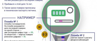
Antimagnetic seals on electric meters and their features
Some consumers are trying to save money on utility bills by “cheating” the magnetic seal on the electric meter. Most often, neodymium magnets are used for this. With their help, the electromechanical counter stops.
For this reason, regulatory authorities install anti-magnetic seals on consumer electricity meters. Outwardly, they resemble a sticker, but its structure is much more complex than it might seem at first glance. Inside the seal there is a sensor that records magnetic changes. When a certain threshold is crossed, the device is triggered. As a result, when the time comes to verify the electricity meter, an employee of the regulatory authorities will be able to determine the presence of outside interference by the appearance of the device.
The sensor itself is a small capsule filled with a substance that reacts sensitively to the presence of a magnetic field. If such an intervention has taken place, the contents spread throughout the capsule. After this, no means can restore it to its original appearance. A completely colored capsule will indicate that an attempt was made to stop the metering device.
Anti-magnetic seal for electric meter
How much does it cost to seal an electricity meter?
Sealing is carried out when it is time to replace the electric meter or there is a need for its repair. All costs for servicing the device are covered by the owner, but installation of the seal is performed free of charge. If repairs or replacement of the electric meter are expected, the price is already included in the cost of these procedures. If they resort to sealing again, in this case the service will need to be paid (from 100 to 500 rubles, depending on the region of residence).
Forcing the owner to pay for the initial installation of a seal after the above maintenance is considered illegal. In such cases, there are several ways to solve the problem:
- Pay the required amount, immediately receive a receipt confirming the fact of payment with the obligatory indication that the assigned amount was taken specifically for installing the seal. This document may become the basis for filing a complaint with higher regulatory authorities that a fee is illegally charged for the provision of a free service.
- File a claim in court.
- Submit an application to the service involved in antimonopoly activities (FAS).
Initial sealing of the meter is free of charge
It is worth noting that for household electricity meters the price for installing a seal is low, so the apartment owner independently decides whether to pay for this service or not.
Taking readings from induction meters
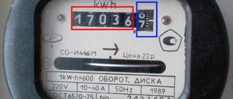
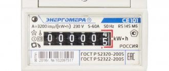
Induction meters can be distinguished by a spinning wheel, which is located just below the frame with numbers. These numbers are the meter readings. The number of digits depends on the model.
How to take readings from an inductive and electronic electricity meter
How many numbers to write off
Typically, the induction meter display has 5, 6 or 7 digits. In most cases, the last digit, less often two, are separated by a comma, color, or differ in size. We do not take into account all numbers after the decimal point when taking readings . They show tenths and hundredths of a kilowatt and should not be taken into account. That is, we do not take into account all the numbers after the decimal point.
There are models with three “significant” digits and two after the decimal point
There are electricity meters that do not have decimal numbers. Then, when taking readings, write down all the numbers
But it is worth remembering that there are counter models that do not have a comma. In this case, when taking readings, you must write off all the numbers. If you don’t do this, sooner or later you will have to pay the difference, and it usually turns out to be very large. So be careful.
If you are unsure whether your meter has a comma, write down the model, name and call the customer service of the organization that supplies electricity. Let them clarify how many numbers in your case need to be written off when taking readings. You can also call an inspector to your home or check this data with the electrician of the management company.
How to shoot
Immediately after installing the meter, you were given a certificate in which the initial numbers are indicated. When you come to take readings from the light meter, take a piece of paper and copy down the current readings there (without taking into account the numbers separated by a comma). You can also not rewrite the zeros that appear at the beginning - up to the first digit (see photo).
Example of induction meter readings
For further calculations, data for the previous month is required. In the first month of use, you take them from the installation report, and in the future you need to either keep receipts or keep an accounting log. Where and how they will be stored is your choice.
Some subscriber services work in such a way that you don’t even need to count anything, you just need to transfer data within a certain period of time. Their automated system will write it to your personal account (or the operator will do it), then make the charges independently and generate a receipt. All you have to do is pay the invoice. But even in this case, for control, you can calculate how much you should pay for electricity yourself. Of course, it is unlikely that computers will make a mistake (they think), but you never know...
How to count
To calculate the electricity on the meter yourself, subtract the one that was there before from the number you just wrote. You get the number of kilowatts consumed over the last period.
For example, consider the readings in the photo above. Let the previous ones be 4852, the current ones 5101 (we ignore the numbers after the decimal point). We calculate the electricity consumption: 5101 - 4852 = 249 kW. To find out how much you need to pay, you need to multiply the resulting number of kilowatts (in this case 249 kW) by the tariff. Get the amount you have to pay for the light.
If the counter stands for a long time, sooner or later it will “reset to zero” - zeros will appear in the first positions. How to calculate electricity consumption in this case? Everything is very simple. This time you will have to rewrite the readings with all zeros, and put a “1” in front of the first one. For example, you asked to take readings from the meter, but only the last digits are different from zero. Or, as in the photo below, it costs only one.
After zeroing, there may be a picture like this, or there may be two digits other than zero, or three...
You rewrite the value as is, with all zeros (but we don’t write numbers after the decimal point), put a unit in front of the first zero, and then count as before. Let's count the readings in the photo. We write off the reading, putting “1” in front: 100001. Let the last reading be 99863. Subtract 100001 - 99863 = 138 kW. Total consumption for the reporting period was 138 kW. In the future, you write off the electric meter readings as before, without leading zeros and without substituting a unit.
What is the accuracy class of an electric meter?
For electrical measuring instruments, the international standard provides for several accuracy classes that determine the quality of measurements. In accordance with the class, on the body of the device, a corresponding digital designation is applied, indicating the percentage error that is permissible in measurements, that is, it cannot significantly distort the readings in favor of any of the parties.
What are the accuracy classes?
In accordance with the international measurement system SI, the following main classes are provided for electrical measuring instruments:
- 0,05.
- 0,1.
- 0,2.
- 0,5.
- 1,5.
- 2,5.
The order of the class is inversely proportional to its digital value, that is, the lower the number, the higher the class. To establish the percentage of error or the fact that it exceeds its limits, a verification is carried out - a comparison of the readings of the meter being verified and the reference one.
As the latter, any device with a class one or more levels higher can be used. The most accurate instruments with a class of 0.05 and higher, as a rule, are laboratory samples not used in industry, for household consumers; such high accuracy is also not necessary.
How to take readings from three-phase meters
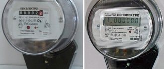
There are two types of three-phase electricity meters - the old type, which requires transformers, and electronic direct connection (without transformers). If an electronic one is installed, the electricity meter readings must be taken in the same way as described above. Simply write down the values, wait until the necessary information is displayed on the screen, or “scroll” the data to the required page.
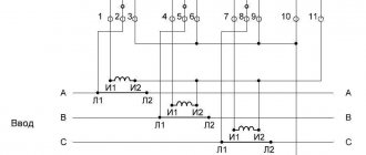
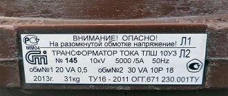
Connecting an electric meter in a three-phase network via current transformers
If a large amount of power is allocated or an old-style meter is installed, a transformer is installed on each of the phases. To take readings in this case, you need to know the transformation ratio. The readings taken must be multiplied by this coefficient. The resulting figure will be the actual expense.
But in general, you need to read the contract. The calculation procedure must be prescribed there - in some organizations they write out readings, put down the transformer data or transformation ratio, and the actual calculations are made by the operator himself. So, if you have a 3-phase meter, check the form and procedure for calculations when installing and sealing the metering device and putting it into operation.
Electric meter
The measurement of any physical quantity always occurs with errors, and in order for the calculation based on the measurement to be the most accurate, measuring instruments of the appropriate accuracy class are used. Electrical measurements, in particular, the consumption of electricity, are no exception. Assignment to any of the accuracy classes indicates the range within which the actual measurement value can fluctuate, that is, this is the percentage ratio of the accuracy class to the maximum value on the scale. Despite the fact that an electric meter is considered exclusively a household appliance, it can have different classes and be used not only by household subscribers.
The principle of operation of the electric meter
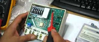
Everyone has an electricity meter in their home. And there is not a person who would not wonder how this unknown black box works, what it consists of, and whether it is really possible to make it spin in the opposite direction. Today we will satisfy your curiosity and look under the seal that blocks access to the internal structure of this very interesting device.
What types of electric meters are there?
Based on the operating principle of the counting mechanism, these devices are of three types:
- Mechanical - they are based on a gear reducer, which drives that same mysterious rotating disk.
- Electronic - the count is carried out by a pulse generator, the results are displayed on a liquid crystal display.
- Hybrid - the pulse generator is paired with a stepper motor, similar to those used in quartz watches. The results are given in the same way as with mechanical instruments - by numbers on bit rings driven by a gear reducer.
The most interesting thing is that the operating principle of the electric meter is based on the same phenomenon - electromagnetic induction.
And yet it spins!
The design of an electric meter is most clearly seen in the example of a single-phase household device of a mechanical type. Its circuit diagram is shown in the figure below.
- W-shaped core
- U-shaped core
- Gearbox
- Permanent magnet
- Disk
A coil with a small number of turns mounted on a U-shaped metal core is connected to terminals 1 and 2, into which the phase wire is clamped. It is called current because the connection is sequential. Another wire is also connected to terminal 1, going to another coil with a large number of turns and mounted on an W-shaped metal core.
The connection point is detachable, the fastener is a screw called a “voltage screw”, since the second end of the coil is connected to terminal 3, to which the neutral wire is connected and the connection is parallel. The coil cores are located at an angle of 900 to each other, and in the gap between them is the edge of the aluminum disk.
When an alternating electric current passes through the coils, a pulsating magnetic field is induced in the cores. Their product is a vortex magnetic flux, always rotating in one direction.
Advice
According to the law of electromagnetic induction, this vortex induces an electric current in the aluminum disk and forces it to rotate after itself.
Since both the voltage in the network and the current are taken into account, the consumption of electrical power is measured, which is the product of these quantities.
All this is very reminiscent of the design of an asynchronous single-phase electric motor with starting and operating windings. The only difference is that the electricity meter is a measuring machine, so for the accuracy of the readings, it is necessary to exclude all factors that can change them.
For example, moment of inertia. That is why the rotor, the role of which is played by the disk, is made of aluminum - the lightest electrically conductive material that is not subject to secondary magnetization. The disc-shaped shape was chosen because a side effect of electromagnetic induction is the heating of metals by so-called Foucault currents.
In flat-shaped conductors they attenuate faster. This property is used, for example, in high-voltage high-power transformers, the primary winding of which is made of a rectangular conductor.
The second difference between a mechanical counter and an asynchronous motor is the presence in its design of a brake - a permanent magnet located at the edge of the disk.
It is needed so that the rotation is uniform, without acceleration, and the stop occurs instantly, without coasting.
The position of this magnet can be changed by changing the amount of electrical power to which the device does not respond. The normal factory setting is 25W.
The disk is mounted on an axle, at one end of which there is a worm gear. Through it the gearbox of the counting mechanism is activated. Changing the positions of the windings can indeed lead to reversal.
note
To do this, you just need to change the connection order: apply the phase to terminal 3 and remove it from the fourth. To combat fraud, a ratcheting mechanism is installed in the gearbox that blocks rotation in the opposite direction.
Three-phase mechanical counting devices are designed in a similar way.
But there are subtleties: if the circuit is built with a solidly grounded neutral - the phases at the output of the substation power transformer are connected by a star and the line consists of three conductors, then the meter has two disks on the same axis.
Letter designations in electrical diagrams
We have already discussed a similar article: decoding cables and wires. If you have read this article, it will be easier for you to understand all the letter symbols. According to GOST 7624-54, the letter designation of elements on electrical circuits looks like this:
- KV – limit switch.
- PV – travel switch.
- DO – cooling pump motor.
- DP – feed motor.
- DS – spindle motor.
- DBH is a high-speed engine.
- DG is the main engine.
- CC – command controller.
- KU – control button.
- Voltage, power, time, index, current relay, respectively - RT, RN, RM, RS, RV, RP, RU, RG, RTV.
Radio technical elements on electronic circuits are designated as follows.
So we have figured out what electrical symbols exist on the circuits, watch this interesting video, it will help you understand some of the features.
Marking examples
With the invention of electronic metering devices, a large number of manufacturers of these products appeared. There was no unified system by which the labeling of electricity meters could be determined. Each manufacturer uses its own product designation.
Let's consider what markings are used by the manufacturer producing the Mercury 230 electric meter. In addition to the name itself, the marking of the electric meter may contain symbols, the explanation of which is given below.
- Type of measured energy (A – active, R – reactive, AR – both types).
- Marking (T) indicates the presence of an internal rater.
- The number 2 means that electrical metering is carried out in two directions.
- P – there is an event log (the facts of disconnection and opening of the meter are recorded).
- Q – power quality control (voltage, frequency, harmonic distortion).
- C – presence of a CAN interface for communication with external devices.
- I – infrared port is installed. The device is typically used for remote readings.
- G – built-in GSM modem. Such an electric meter is capable of independently transmitting readings and other information via a cellular communication channel.
- L – PLC modem. This device uses low-voltage electrical networks to transmit information.
- M – modified PLC modem.
- OS – the design contains a reporting device.
- USPD - the meter contains a device for collecting and transmitting data. Used in automated accounting systems - ASKUE, ASTUE.
- B – a backlit indicator is used.
- S – interface is equipped with internal power supply.
- D – the electric meter is equipped with backup power.
- N – sealing is performed using an electronic seal, which is an autonomous microprocessor device equipped with memory. An electronic seal records the fact that the meter has been opened and can independently transmit a signal.
- O – the device has a built-in load control relay. This function allows you to turn off the load either manually, using a button, or by programming the shutdown when the set consumption limits are reached.
- K – ability to control external devices to disconnect the load.
We also provide for your attention a transcript of another popular electricity meter from the Energomera company - TsE6803V:
Well, maybe someone will find the markings of the GAMMA 1 multi-tariff electricity meter useful:
Now you know what the markings of electricity meters look like and their interpretation. We hope that the information provided was useful to you and now you can determine the characteristics of the meter yourself based on the symbols located on the front panel of the device!
We also recommend reading:
- How to mark wires in an electrical panel
- Characteristics of the electricity meter Mercury 201
- Decoding the markings of wires and cables
Published: 04/28/2017 Updated: 11/04/2017
How the marking of an induction electric meter is deciphered: let’s look at an example
Like all devices, the electric energy meter is marked with letters and numbers. These designations show the voltage value, connection method, accuracy classification, etc.
Today there are several types of markings for electric meters, so we will talk about the standard designation on electrical metering devices.
As an example, we will consider the labeling of induction meters and the Mercury 230 electronic metering device.
Induction electricity meters
To select a suitable energy meter, you need to understand what the letters and numbers on its panel mean.
Above is a diagram of the decoding of the symbols. The markings shown are used for single and three phase meters.
The first letter “C” indicates the type of device. The second letter shows the type of energy counted by the meter. “A” is active energy, “R” is reactive energy. There is no such marking on meters with one phase, since they measure only the active load.
The third position can be a letter or a number. On devices with the 1st phase there will be the letter “O”, with three phases the type of conductor will be indicated, 4 – four wires, 3 – three wires (there is no zero), if there is a letter “U” - the meter is universal.
The letter “I” indicates that the device is induction.
- model series;
- type of execution, in this case “M” is a modernized model. There may be the letters “T” - tropical version and “P” - direct connection;
- operating voltage and current load indicators;
- year of manufacture and number.
Procedure for studying drawings
How to read electrical diagrams correctly and understand the information presented on the drawing? It is enough to be able to navigate the graphical symbols of GOST; this is the basis of each developed project.
First, determine the type of drawing. According to GOST 2.702-75, each graphic document has an individual code. All electrical drawings have the letter “E” and a corresponding digital value from 0 to 7. The electrical circuit diagram corresponds to the code “E3”.
Reading the circuit diagram:
Visually familiarize yourself with the presented drawing, pay attention to the specified notes and technical requirements. Find on the schematic diagram all the components indicated in the list of the document; Determine the power source of the system and the type of current (single-phase, three-phase); Find the main components and determine their power source; Familiarize yourself with protection elements and devices; Study the management method indicated on the document, its tasks and algorithm of actions. Understand the sequence of actions of the device when starting, stopping, short circuit; Analyze the operation of each section of the circuit, determine the main components, auxiliary elements, study the technical documentation of the listed parts; Based on the studied document data, draw a conclusion about the processes occurring in each link of the circuit presented in the drawing. Knowing the sequence of actions, alphabetic symbols, you can read any electrical circuit
Knowing the sequence of actions, alphabetic symbols, you can read any electrical circuit.
What is k2 on the counter?
K2
- this is a light indicator of the presence of a difference of more than 12.6% between the current in the phase circuit and the current in the zero circuit; (from the manufacturer's website.)
Interesting materials:
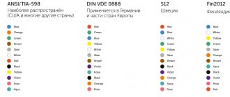
How to choose a left or right hockey stick? How to choose a Bluetooth codec? How to choose the number of processor cores? How to choose a jbl column? How to choose a computer for a designer? How to choose a computer for home use? How to choose a computer for Photoshop? How to choose a computer for studying? How to choose sunscreen for your face? How to choose a new crossover?
Graphic
As for the graphic designation of all elements used in the diagram, we will provide this overview in the form of tables in which the products will be grouped by purpose.
In the first table you can see how electrical boxes, panels, cabinets and consoles are marked on electrical circuits:
The next thing you should know is the symbol for power sockets and switches (including walk-through ones) on single-line diagrams of apartments and private houses:
As for lighting elements, lamps and fixtures according to GOST are indicated as follows:
In more complex circuits where electric motors are used, elements such as:
It is also useful to know how transformers and chokes are graphically indicated on circuit diagrams:
Electrical measuring instruments according to GOST have the following graphic designation on the drawings:
By the way, here is a table useful for novice electricians, which shows what the ground loop looks like on a wiring plan, as well as the power line itself:
In addition, in the diagrams you can see a wavy or straight line, “+” and “-”, which indicate the type of current, voltage and pulse shape:
In more complex automation schemes, you may encounter incomprehensible graphic symbols, such as contact connections. Remember how these devices are designated on electrical diagrams:
In addition, you should be aware of what radio elements look like on projects (diodes, resistors, transistors, etc.):
That's all the conventional graphic symbols in the electrical circuits of power circuits and lighting. As you have already seen for yourself, there are quite a lot of components and remembering how each is designated is possible only with experience. Therefore, we recommend that you save all these tables so that when reading the wiring plan for a house or apartment, you can immediately determine what kind of circuit element is located in a certain place.
Interesting video on the topic:
We have already told you how to decipher the markings of wires and cables. Single-line electrical circuits also have their own letters, which make it clear what is included in the network. So, according to GOST 7624-55, the letter designation of elements on electrical circuits is as follows:
- Relays for current, voltage, power, resistance, time, intermediate, indicating, gas and time-delayed, respectively - RT, RN, RM, RS, RV, RP, RU, RG, RTV.
- KU – control button.
- KV – limit switch.
- CC – command controller.
- PV – travel switch.
- DG is the main engine.
- DO – cooling pump motor.
- DBH is a high-speed engine.
- DP – feed motor.
- DS – spindle motor.
In addition, in the domestic marking of elements of radio engineering and electrical circuits, the following letter designations are distinguished:
This completes a brief overview of symbols in electrical circuits. We hope that now you know how sockets, switches, lamps and other circuit elements are indicated on drawings and plans of residential premises.
Home » Electrical » Designation of electrical elements on diagrams
GOST 25372-95 Symbols for AC electrical energy meters
GOST
25372-95 (IEC 387-92)
INTERSTATE STANDARD
SYMBOLS FOR AC ELECTRIC ENERGY METERS
INTERSTATE COUNCIL FOR STANDARDIZATION, METROLOGY AND CERTIFICATION
Minsk
Preface
1. DEVELOPED by the All-Russian Research Institute of Standardization and Certification in Mechanical Engineering (VNIINMASH)
INTRODUCED by Gosstandart of the Russian Federation
2. ADOPTED by the Interstate Council for Standardization, Metrology and Certification (Protocol No. 8 of October 12, 1995)
The following voted for adoption:
| State name | Name of the national standardization body |
| The Republic of Azerbaijan | Azgosstandart |
| Republic of Belarus | State Standard of Belarus |
| The Republic of Kazakhstan | Gosstandart of the Republic of Kazakhstan |
| The Republic of Moldova | Moldovastandard |
| Russian Federation | Gosstandart of Russia |
| The Republic of Tajikistan | Tajikgosstandart |
| Turkmenistan | Main State Inspectorate of Turkmenistan |
| Ukraine | State Standard of Ukraine |
3. This standard contains the full authentic text of the international standard IEC 387-92 “Conventions for alternating current electricity meters” with additional requirements reflecting the needs of the country’s economy
4. By Decree of the Committee of the Russian Federation on Standardization, Metrology and Certification dated March 27, 1996 No. 212, the state standard GOST 25372-95 (IEC 387-92) was put into effect directly as the state standard of the Russian Federation on July 1, 1996.
5. INSTEAD GOST 25372-82
6. REPUBLICATION. March 2005
Content
| 1 area of use 2. Normative references 3. Terms and definitions 4. Symbols for measuring elements of meters 5. Symbols of units of physical quantities used for meters 6. Marking of the measured value 7. Symbols of accuracy class, meter constant, meter gear ratio and insulation protection class 8. Symbols for meters connected via instrument transformers 9. Symbols of charging devices 10. Symbols for auxiliary devices 11. Symbols for parts of the suspension of the movable element of the meter 12. Warning symbols APPENDIX A (recommended) SYMBOLS FOR SIGNAL HOLES |
INTERSTATE STANDARD
| SYMBOLS FOR AC ELECTRIC ENERGY METERS Symbols for alternating-current electricity meters |
Date of introduction 1996-07-01
This standard applies to letter and graphic symbols for alternating current electric energy meters (hereinafter referred to as meters) and their auxiliary devices, regardless of the measuring elements of induction or static meters.
Model electricity meters and their auxiliary devices can be marked with symbols that differ from those established in this standard.
The symbols specified in this standard may be printed on the shield, dial, external labels or auxiliary devices of meters.
All requirements of this standard, except 6.6 of Table 3 and Appendix A, are mandatory.
Additional requirements for symbols for electricity meters, reflecting the needs of the country's economy, are highlighted in italics in the standard.
This standard uses references to the following standards:
GOST 8.417-2002 State system for ensuring the uniformity of measurements. Units of quantities
GOST 23217-78 Analogue electrical measuring instruments with direct reading. Applied symbols
This standard uses the following terms:
3.1. induction meter for electrical energy:
An electric energy meter, the operation of which is based on the rotation of the disk of an induction measuring mechanism.
3.2. static electricity meter:
An electrical energy meter in which current and voltage are applied to solid-state (electronic) elements to produce output pulses whose number and frequency are proportional to the energy and power, respectively.
3.3. watt hour meter:
An instrument designed to measure active energy by integrating active power over time.
3.4. var-hour counter:
An instrument designed to measure reactive energy by integrating reactive power over time.
3.5. volt-amp hour meter:
An instrument designed to measure apparent energy by integrating the apparent power over time.
3.6. multi-tariff electric energy meter:
An electric energy meter equipped with a set of counting mechanisms, each of which operates at set time intervals corresponding to different tariffs.
3.7. excess electrical energy meter:
Electric energy meter designed to measure excess electrical energy during the time when the power value exceeds a predetermined value.
3.8. maximum indicator (for counter):
A device attached to a meter to indicate the highest value of average power used during successive equal intervals of time.
3.9. maximum counter:
Counter equipped with a maximum indicator.
3.10. bidirectional counter:
A meter designed to measure electrical energy in both directions.
3.11. Memory device:
An element designed to store digital information.
3.12. display:
A device that displays information from storage device(s).
3.13. counting mechanism:
An electromechanical or electronic device containing both a storage device and a display that stores and displays information.
If the meter is used with current and (or) voltage transformers, then the counting mechanism can be primary, secondary and mixed.
One display can be used with several electronic storage devices to form multi-tariff counting mechanisms.
3.14. primary counting mechanism:
The counting mechanism of a meter connected through measuring transformers, which takes into account the transformation ratios of all transformers (voltage and current transformers), but does not take into account the transformation ratios of both at the same time.
NOTE The energy value is obtained by direct reading of the counting mechanism.
3.15. mixed counting mechanism:
The counting mechanism of a meter connected through instrument transformers, which takes into account the transformation ratio(s) of the current or voltage instrument transformer(s), but does not take into account the transformation ratios of both simultaneously.
Note - The energy value is obtained by multiplying the readings of the counting mechanism by the appropriate coefficient.
3.16. secondary counting mechanism:
The counting mechanism of a meter connected through instrument transformers, which does not take into account the transformation ratio(s).
Note - The energy value is obtained by multiplying the reading of the counting mechanism by the appropriate coefficient.
3.17. meter panel:
A plate that is easily accessible for reading, fixed inside or on the outer surface of the meter, on which the values corresponding to the conditions of use of the meter are indicated, and on which symbols can also be applied.
3.18. clock face:
Part of the reading device on which the scale or scales and symbols characterizing the device are applied
Note - In some cases the shield and dial may be combined.
3.19. counter constant:
A coefficient expressing the ratio of the counted energy to the number of revolutions of the counter disk (rotor) or to the number of output pulses.
The counter constant is expressed in units of counted energy per number of revolutions of the counter disk (rotor) or the number of output pulses.
Gear ratio of the meter: - The inverse of the value of the meter constant and is expressed in disk (rotor) revolutions or pulses per unit of counted energy.
3.20. counting coefficient C of the maximum indicator:
The factor by which the reading in power units (active or reactive) must be multiplied to obtain the corresponding power value expressed in the same units.
3.21. constant K of the maximum indicator:
The coefficient by which it is necessary to multiply the readings in arbitrary divisions to obtain a value in units of the corresponding power (active or reactive).
In the symbols given in Table 1, each voltage circuit is indicated by a line, and each current circuit is indicated by a circle.
At the end of each voltage circuit line there is a circle(s) to indicate the current circuit(s) sharing a common connection point with that voltage circuit.
If the current circuit and the voltage circuit, having such a common connection point, are not part of the same electromagnet, then the circle indicating the current circuit is connected to a point in the middle of the line indicating the voltage circuit - by means of a directrix with a thickness of no more than half the thickness of the first line , indicating the voltage circuit.
If an electromagnet contains two current circuits and the number of its turns is in the ratio 1: k
, then the diameters of the circles in the designation should be approximately in the same ratio.
The angle between two lines of a symbol represents the phase angle between the corresponding voltages, provided that the positive direction is taken to be the direction going to the common point in the symbol with two lines (for example, symbols 4.9 and 4.10) and the direction within the internal angles of the triangle - for symbols with triangles (for example, symbol 4.8).
To differentiate the direction of voltage acting on each current, the current circuit affected by the positive direction of voltage should be indicated by a filled circle, and the current circuit affected by the negative direction of voltage should be indicated by an open circle.
Table 1 - Symbols for measuring elements of meters
| Designation number | Counter type | Designation |
| 4.1. | Watt-hour or var-hour meter with a measuring element, having one current circuit and one voltage circuit (for single-phase two-wire circuits) | |
| 4.2. | Watt-hour or var-hour meter with one measuring element, having one voltage circuit and two current circuits (for single-phase two-wire or three-wire circuits when the voltage circuit is connected to the outermost wires) | |
| 4.3. | A watt-hour or var-hour meter with two measuring elements, each having one voltage circuit and one current circuit. Current circuits are connected to the outer wires of a single-phase three-wire circuit, and the corresponding voltage circuits are connected between one of the outer wires and the middle wire | |
| 4.4. | A watt-hour or var-hour meter with two measuring elements, each having one voltage circuit and one current circuit. The current circuit is connected to the phase wire of a three-phase circuit, and the voltage circuit of each measuring element is connected between the neutral and the phase wire into which the current circuit is connected | |
| 4.5. | Watt-hour or var-hour meter with two measuring elements, each with one voltage circuit and one current circuit, connected using the two-wattmeter method (for three-phase three-wire circuits) | |
| 4.6. | Watt-hour or var-hour meter with three measuring elements, each with one voltage circuit and one current circuit, connected using the three-wattmeter method (for three-phase four-wire circuits) | |
| 4.7. | Watt-hour or var-hour meter with two measuring elements, each having one voltage circuit and one current circuit, and connected in series with both phase wires of a two-phase three-wire circuit | |
| 4.8. | A var-hour meter with three measuring elements, each of which has one voltage circuit and a current circuit and is placed so as to have a common point with the voltage circuits of the other two measuring elements. The voltage circuit of each measuring element is powered by voltage between the phase wires, which do not include the current circuit, Designation 4.8, corresponding to Figure 1, is used for three-phase three- or four-wire circuits Picture 1 | |
| 4.9. | Var-hour meter with two measuring elements, each of which has one voltage circuit and two current circuits with the number of turns in the ratio 1:2 (n and 2 n turns). Each n-turn circuit shares a common point with the voltage circuit of the same measuring element, while each 2n-turn current circuit shares a common point with the voltage circuit of another element. A circuit with n turns of one of the measuring elements and a circuit with 2 n turns of the other are exposed to positive voltages, as opposed to a circuit with 2 n turns of the first element and a circuit with n turns of the second, which are exposed to negative voltages Designation 4.9, corresponding to Figure 2, is used for three-phase three-wire circuits Figure 2 | |
| 4.10. | Var-hour meter with two measuring elements, each of which has one voltage and current circuit. One of the current circuits has a common point with the voltage circuit of the other measuring element, while the current circuit of the latter has a common point with the voltage circuits of both measuring elements. Designation 4.10, corresponding to Figure 3, is used for three-phase three-wire circuits Figure 3 |
The symbols of the units of physical quantities used for meters are given in Table 2.
Table 2 - Symbols of units of physical quantities used for meters
| Designation number | Unit of physical quantity | Designation* |
| 5.1. | Ampere | A |
| 5.2. | Volt | V |
| 5.3. | Watt | W |
| 5.4. | Watt hour | W h |
| 5.5. | Var | var |
| 5.6. | Var-hour | var h |
| 5.7. | Volt-amps | V A |
| 5.8. | Volt-amp-hour | V·A·h |
| 5.9. | Hertz | Hz |
| 5.10. | Volts squared | V2 h |
| 5.11. | Ampere squared | A2 h |
| 5.12. | Hour | h |
| 5.13. | Minute | min |
| 5.14. | Second | s |
| 5.15. | Degree Celsius | °C |
| * For the needs of the national economy, it is allowed to apply symbols of units of physical quantities in Russian in accordance with GOST 8.417, incl. using notations for multiple and submultiple values of units of physical quantities according to GOST 23217. | ||
The designation in accordance with the requirements of Section 5, indicating the nominal measured value, must be placed on the meter panel or dial in accordance with Table 3.
When the meter is intended for measurements under special conditions (or) at different power factor ranges, the appropriate designation should be used.
If an induction reactive energy meter is adjusted to measure under leading power factor only or lagging power factor only conditions, the direction of normal rotation of the meter disk, when viewed from the front of the meter, will be from left to right, and the counting mechanism should be marked or accordingly. If the meter is adjusted to measure under both lagging and leading power factor conditions, the direction of rotation of the meter disk when viewed from the front of the meter should be from left to right under lagging conditions. Next to each of the two counting mechanisms there must be a marking or
If the meter is intended to measure total energy at certain limiting values of the power factor, then these values must be indicated in parentheses after the symbol of the unit of physical quantity.
Table 3 - Marking of measured value
| Designation number | Type and characteristics of the meter | Designation |
| 6.1. | Active energy meter | kW h |
| 6.2. | Reactive energy meter | k var h |
| 6.3. | Inductive and capacitive reactive energy meter with two counting mechanisms | k var h |
| 6.4. | Apparent energy counter | kVA h |
| 6.5. | Apparent energy meter for a limited power factor range cos φ Example: cos φ = 0.5 ... 0.9 ind. | kVA h (0.5 …0.9) |
| 6.6.* | Operating range of reactive energy meter | |
| * Other designations are possible when measuring energy with a meter in other quadrants. | ||
Symbols for the accuracy class, meter constant, meter gear ratio and insulation protection class are given in Table 4.
Table 4 - Symbols of accuracy class, meter constant, meter gear ratio and insulation protection class
| Designation number | Counter characteristics | Designation |
| 7.1. | Accuracy class Example: Class 1 | or C1. 1 |
| 7.2. | Counter constant for induction meters Example: 500 revolutions per 1 kWh or 2 Wh per revolution | 500 rev/kW h or 2 W h/rev |
| 7.3. | Meter constant for static electricity meters Example: 500 pulses per 1 kWh or 2 Wh per pulse | 500 imp/kW h or 2 W h/imp |
| 7.4. | Class II meter insulation protection | |
| 7.5. | Counter gear ratio for induction meters Example: 500 revolutions per 1 kWh | 500 rev/kW h |
| 7.6. | Meter gear ratio for electricity meters with pulse outputs Example: 500 pulses per 1 kWh | 500 imp/kW h |
Symbols for meters connected via instrument transformers are given in Table 5.
When the meter is powered through instrument transformers, the transformation ratios must be plotted as follows:
Table 5 - Symbols for meters connected via instrument transformers
| Designation number | Counter type | Designation | ||
| on the shield or dial | on the additional panel | |||
| 8.1. | Counter with secondary counting mechanism | 5A, 100 V | 50/5 A, 10000/100 V or A V Multiplier = 1000 | |
| 8.2. | Meter with mixed counting mechanism (primary current is alternating) | 10000/100 V, 5A or V.5 A | 500/5 A or A Multiplier = 100 | |
| 8.3. | Meter with mixed counting mechanism (primary voltage is variable) | 100 V, 50/5 A or 100 V, A | 10000/100 V or V Multiplier =100 | |
| 8.4. | Counter with primary counting mechanism | 10000/100 V, 50/5 A or V, A | — | |
| Note - If there is no space, only one symbol can be placed on the shield: for an instrument transformer. | ||||
The transformation coefficients that are taken into account by the counting mechanism must be marked on the shield or dial of the meter (for primary counting mechanisms - the coefficients of all transformers; for mixed counting mechanisms - the transformation coefficient that is taken into account by this mechanism).
On the additional shield attached to the casing of a meter with a mixed or secondary counting mechanism, transformation coefficients that are not taken into account by the counting mechanism must be marked (for a secondary counting mechanism - the coefficients of all transformers, for a mixed counting mechanism - the transformation coefficient that is not taken into account by this counting mechanism ).
The symbol of the measuring transformer must be marked on the shield or dial of a meter with a mixed or secondary counting mechanism in accordance with 8.1. - 8.3, which means that this meter is designed to work together with such measuring transformer(s), the transformation ratio(s) of which is not taken into account by this counting mechanism. The energy value in these cases is determined by multiplying the reading of the counting mechanism by the corresponding factor.
On the additional panel of meters with a mixed or secondary counting mechanism, a multiplier must be marked by which the reading of the counting mechanism must be multiplied to obtain the energy value in the primary winding of the transformers.
Symbols of tariff devices are given in Table 6.
a) Multi-tariff meters
There is no special symbol for a multi-tariff meter, but the corresponding tariffs must be marked next to the set of scales or the counting mechanism.
Examples: day (normal)
or I
;
nocturnal (low)
or II
;
high (peak) or
III
.
Note - The marking of a meter with a large number of tariffs must be specified in the contract.
b) Excess energy meters
Near the counting mechanism that registers the count of surplus, a symbol should be applied
Table 6 — Symbols of meter charging devices
| Designation number | Type and characteristics of the meter and charging device | Designation |
| 9.1. | Excess energy meter The number next to the triangle indicates the power value at which the excess energy counting mechanism begins to operate Example: 800 W Note - For meters with two fixed operating power limits switched by relay, both operating limits must be marked | 800 W |
| 9.2. | Energy surplus meter, in which the surplus level is regulated | |
| 9.3. | Drum type maximum indicator Example: Multiplier for maximum indicator 0.2 kW, integration interval 15 min, dead time 9 s | 0.2 kW/div = 15 min /9 s |
| 9.4. | Pointer or drum type maximum indicator, equipped with a signaling device | 0.2 kW/div = 15 min/9 s |
| 9.5. | Bidirectional meter Energy received at the measuring point (for example consumption) Energy transmitted at the measuring point (for example income) | |
| 9.6. | Instantaneous (real) value of the average required value | P inst |
| 9.7. | The highest average value required for the current aggregation (billing) period | P max |
| 9.8. | Summed maximum required value | P cum |
| 9.9. | Integration period | t m |
| 9.10. | Dead time | t 0 |
| Note - The symbols given in 9.6 - 9.10 are intended for static meters with a maximum indicator, equipped with a display. | ||
The power value above which excess energy is registered must be indicated next to this designation in the appropriate units, preferably on the additional panel, which must be replaced when the power of the excess changes.
c) Counters with maximum indicator
A meter with a single pointer maximum indicator does not require any designation. It should be marked, for example: k
= 20 kW/division
.
For a meter with a totalizing maximum indicator, the totalizing mechanism must be designated by the appropriate power unit.
The maximum value of the measured average power and the corresponding symbol must be marked on the maximum indicators near the counting mechanism. The unit of the recorded value must be indicated on the adding counting mechanism, if available.
d) Bidirectional counters
If the meter is designed to record received or transmitted energy by means of two rows of dials or drums, then each of them must be indicated by an arrow indicating the appropriate direction. If received or transmitted energy is recorded by reactive energy meters, then an additional panel must be provided for the symbols given in 9.5.
Symbols for auxiliary devices are given in Table 7.
Table 7 - Symbols for auxiliary devices of meters
| Designation number | Type and characteristics of the meter and auxiliary device | Designation |
| 10.1 | Counter with pulse sensor The designation indicates the number of pulses per kWh or the number of Wh per pulse Example: 10 imp/(kWh) or 100 Wh/imp. | 10 impAWh or 100 Wh/imp |
| 10.2 | Meter with moving part lock | |
| 10.3 | Auxiliary supply voltage for static electricity meter (if separated from measuring voltage) Example: 100 VAC | Ux = 100 V 50 Hz |
| 10.4 | Type and value of the auxiliary voltage of the multi-tariff meter relay (must be indicated on the connection diagram) Example: 60 VDC | 60V- |
| 10.5 | Backstop (mechanical or electronic device that prevents backlash) |
Recommended symbols for marking signal holes are given in Appendix A.
Symbols for the suspension parts of the meter's moving element are given in Table 8.
Table 8 - Symbols for parts of the suspension of the moving element of the meter
| Designation number | Part type | Designation |
| 11.1. | Lower bearing with two supports made of precious or artificial stones | |
| 11.2. | Magnet for partially releasing the bearing from the load from below | |
| 11.3. | Movable element with magnetic suspension or support | |
| 11.4. | Magnet for partially releasing the bearing from the load from above |
Any references to an independent document must be indicated on the plate with the designation
Table A.1
| Designation number | Type of signal hole | Designation |
| A.1. | Optical hole, bi-directional | |
| A.2. | Induction hole, bi-directional | |
| A.3. | Electroplated hole, unidirectional | |
| A.4. | Hole in accordance with a special standard, such as TEMEX, ISDN, etc. | |
| Note - Communication directions: output (for example, count); input (eg programming); continuous connection; connection only on demand (eg password, switch) | ||
Keywords
: electricity meters, alternating current, symbols, letter symbols, graphic symbols