Melted housings of junction boxes, burnt wires, violation of the integrity of the cores are the consequences of neglecting such a procedure as cable termination. Without creating reliable contact with the device, you cannot be sure that the electrical wiring is safe. Using termination, you can reduce the transition resistance that causes contact melting, increase the reliability of the connection and increase its service life. There are different methods for terminating wires, each of which has its own positive and negative sides.
How to connect electrical wires by soldering
Connecting electrical wires by soldering is very reliable.
You can solder untwisted wires, but such soldering will be fragile due to the fact that the solder is a very soft metal. In addition, it is very difficult to lay two conductors parallel to each other, especially when suspended. And if you solder on some kind of base, the rosin will stick the soldering area to it. A layer of rosin is applied to the pre-tinned and twisted conductors with a soldering iron. If another flux is used, it is applied in the appropriate manner. The power of the soldering iron is selected based on the cross-section of the wire - from 15 W when soldering headphones to 100 W when soldering twisted wires with a cross-section of 2.5 mm². After applying the flux, tin is applied to the twist with a soldering iron and heated until the solder completely melts and flows into the twist.
After the soldering has cooled, it is insulated with electrical tape or a piece of heat-shrinkable tubing is put on it and heated with a hairdryer, lighter or soldering iron.
When using a lighter or soldering iron, be careful not to overheat the heat shrink.
This method reliably connects wires, but is only suitable for thin wires, no more than 0.5 mm², or flexible ones up to 2.5 mm².
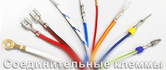
What types of tips are there?
Separately, we wanted to tell you about the types of tips and their main features. After all, terminating wire strands is not difficult, even if you use pliers. However, if you choose the wrong tip, you cannot avoid trouble.
The following types of tips are currently distinguished:
- TML is a copper tip that has a tinned shell.
- TM – made of copper, no shell.
- TML(o) – copper, with tinned shell. It has an additional hole that allows you to visually determine whether the core is completely clamped.
- TA – ordinary aluminum.
- TAM – aluminum body, copper end. It allows you to connect an aluminum wire to a copper bus.
- PM – made of copper, intended for soldering.
- NB - bolted. Using them you can tighten the wire with an ordinary bolt.
So we figured out which lugs you can use to terminate a cable or wire yourself
Please note that according to the PUE, termination of wires can only be carried out with a cross-section from 0.75 mm2 to 240 mm2. Therefore, when choosing, pay attention to the appropriate markings:
- YY is the diameter of the hole into which you can insert the conductor.
- XX is the cross-section of the wire under crimp.
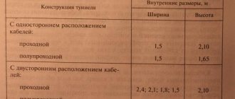
Technical characteristics of the AAShV cable.
Common types of tips
In electrical installation practice there are dozens of types of connectors. This diversity is due to the wide list of wires used. Each type of cable has its own tip. It must match the material and cross-section of the current-carrying conductor.
Copper tips TM
Manufactured from seamless tube. This is indicated by the letter - T. The tube is made of copper - M. The full marking looks like this: TM 35-10-9. Here:
- T - tube;
- M - copper;
- 35 - cross-section of the cable for which this tip is intended, sq. mm;
- 10 — diameter (grade) of the fastening screw, mm;
- 9 is the diameter of the shank, that is, the hole into which the cable core is inserted.
If dimensions allow, the tip model is indicated on its surface. If it is too small, then the nominal cross-section of the connected cable is stamped on the product body. For example, the number “4” next to the mounting hole means that a conductor with a cross-section of 4 square meters should be inserted into the tip. mm.
Copper with tinning TML
Copper is a good conductor of electric current. However, a greenish coating is often found on TM tips. This is a layer of copper oxide, which is no good for reliable current transmission. To combat this phenomenon, the tips are additionally coated with a protective anti-corrosion tin coating. The resulting product here means tinning. Otherwise, the TM and TML markings are similar.
Tinned wire lugs
The protective layer prevents oxidation of the copper tip. Therefore, it can be used in more humid areas. Due to increased reliability, TML is suitable for connecting critical electricity consumers.
Tinned copper with control window TML (o)
Before installing the current-carrying conductor into the tip, the protective insulation layer is removed from it. There are a couple of subtleties:
- The stripped core should completely enter the tube and rest against its end. There should be no void left in the tip cavity.
- The cable must be stripped to a minimum length. So that there is no exposed section of wire without insulation left at the tip shank.
Aluminum TA tips
This type of connector is made of aluminum tube. This is indicated by the letter "A". TA lugs are designed for branching aluminum wires from busbars of similar material.
TAs have a long service life. Aluminum has increased resistance to moisture from the air and is practically not destroyed by it. This material is several times cheaper than copper, so sometimes people choose aluminum fasteners.
Aluminum cable lugs
TA are produced for wires with a cross-section of 16 square meters. mm and above. They also require the use of quartz-vaseline lubricant for additional surface protection.
Copper-aluminum TAM
The structure of these connectors uses two metals: copper and aluminum. They are connected to each other through frictional diffusion. One metal penetrates another at the molecular level. Therefore, high contact resistance is avoided.
Other types of tips
The types of fasteners listed are not sufficient to perform all electrical tasks. Therefore, in practice, other types of tips are often found:
- PM - cable lugs for soldering. They are made from sheet copper grade M1. In addition to soldering, this type of tip is also suitable for crimping. Available for cables with cross-sections from 2.5 to 240 sq. mm.
- NShP - pin flat. Used to connect copper cables. Made of copper. The main purpose is to connect wiring to circuit breakers. Inside it has ring notches to improve contact with the current-carrying conductor.
- NShV - pin bushing. Common in modern equipment. Made of electrical copper with a protective coating. Used to connect multi-core copper wires with a cross-section from 0.25 to 150 square meters. mm.
- NSHVI - insulated pin bushing. Equipped with an additional insulating plastic skirt.
Connection using terminal blocks
Electricians often use terminal blocks to connect wires, as it is simple and quite reliable. Almost all types of terminal boxes are designed for screw connections of electrical wires. It is possible to select terminal boxes for any number of wires, as well as for any cross-section. In other words, manufacturers produce these boxes in different sizes.
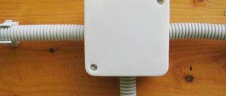
Connecting wires in terminal blocks
The terminal box is a plastic housing that houses terminal blocks with screws. The terminal block has special sockets into which the wire, stripped of insulation, is inserted and clamped. After the wire is clamped with a screw, you should check how reliable this connection is. To do this, just pull the wire with force. This type of connection is characterized by the fact that the connection points remain uninsulated, so it is used in conditions where the room is dry, without the presence of humidity, especially increased humidity.
A disadvantage is the fact that aluminum conductors are quite plastic and lead to weakening of the contact. This, in turn, increases its resistance, which leads to heating of the attachment point. In order for the contacts to remain reliable, they need to be tightened from time to time.
The advantages include ease of connection and its reliability, as well as low cost and connection speed. In addition, terminal blocks allow you to connect wires of different types and different cross-sections. In addition, the design of the terminal blocks is such that there is no accidental contact with live wires.
A simple terminal block and easy modification. Let's do it simply but RELIably!!
What is termination
Wire termination is one of the simplest and most reliable ways to connect wires to terminal blocks, circuit breakers and other electrical equipment. This type of connection is common in household and industrial networks. This is due to the advantages that termination allows to achieve:
- reliable contact patch;
- ease of installation;
- low connection resistance;
- general aesthetics of the wiring.
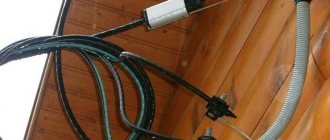
Power cables with lugs The main advantage of terminating cable cores is the low contact resistance of the resulting contact.
If it is not used, the wire will not be able to properly press the screw onto the terminal block bus. This will cause the contact resistance to be too high. A bad connection will start to heat up or completely burn out. Stranded wire crimping
The procedure for crimping tips and sleeves
For crimping thick-walled tips and sleeves, it is best to use a hydraulic press. The press set initially includes universal dies for any tips and wires. Under no circumstances use a tool not intended for crimping (hammer, chisel, etc.). A contact pressed in this way will not last long, especially if it constantly experiences heavy loads.
- from tip length
- and matrix width
In the operating instructions for the press that comes with the tool, there is a plate indicating the required number of crimps. Please note one thing: this table is intended for tips and sleeves made in accordance with GOST. How they differ from other brands can be found in the article Cable lugs, markings and types.
Insert the tip into the press so that the matrix cross-section markings (35-50-70, etc.) are imprinted on the front side of the tip, and not on the side or bottom.
- The first crimping of the tip should be done closer to the blade (where the bolt is inserted)
- Perform the following crimps in order, moving from the blade to the tail of the tip
- the same rules apply for sleeves
This must be done in this sequence, because with each press the tip tends to lengthen (sometimes up to ten percent!). And if you start pressing from the end (not from the blade), during the last crimp, there is a high probability that you will have a void at the end of the sleeve. And you will not achieve the contact that was necessary.
First of all, this applies to all aluminum products. For copper this is not yet so critical.
When crimping from the side of the blade, the tip will seem to fit onto the core, tightening the connection more and more. The insulated tips even have special digital markings indicating the pressing order.
The crimping ends at the moment when the matrices close together. If you need to perform two or three crimps, step back 2-3mm from the previous crimping point and continue crimping.
When crimping, the formation of a small flash is acceptable. It can be removed or filed off. A very common mistake is the formation of large “ears” on the tip. This results from an incorrect choice of matrix.
If such “ears” do appear, you should not cut them down to the base of the sleeve. Otherwise, a gap may form in the tip and the crimp contact will become loose.
After the tip is crimped, it is advisable to insulate the area between where the shank ends and the remaining uninsulated part of the core. It is best to use heat-shrinkable tubing for this.
Wire preparation technology
Press pliers for crimping sleeves and wires
You can do the termination yourself with a special tool. The technology is simple - just take the tip, put it on the conductor all the way and crimp it. The number of clamps can be different - crimping of a matrix with point contact is carried out in two or more places, and for sleeves one crimp is sufficient. Several crimping tests are necessary for more reliable contact, reducing contact resistance and increasing mechanical strength.
Crimping is carried out by professional craftsmen using expensive special tools. For a home specialist, buying such a device is unprofitable, so they choose other options. An alternative can be a stripper for removing insulation with a press or a crimper (special crimp). All devices can be purchased at a regular hardware or electrical store.
There are solder tips. Then termination is carried out in two stages - the stripped core is placed in the tip and solder is poured into the hole. This is a more reliable and high-quality method, which is often used in electrical wiring.
Other causes of heating
Wires and contacts, as already mentioned, can heat up due to the increased load. There are three possible problems here:
- The conductors are very thin, you may notice heating when the load on the electrical wiring increases, for example, in winter, when you start using an electric heater. Then the wires in the shield need to be replaced with thicker ones.
- Heating of the zero in the tire. In this case, the most likely problem is poor contact of the bus screw terminals. To ensure contact, do the same as with the machine - clean and tighten the screw.
- “Extra current” flows through the neutral wire. This is possible if your zero is used by a neighbor to steal electricity or due to unintentional errors during electrical installation. You need to check all connections; you may have to open the grooves in the walls or use a device to find hidden connections.
The zero in the meter rarely gets warm; it is used there only for measurements.
§ 41. General information about cable core connections
To connect cable cores to electrical devices, they are terminated with lugs, which are secured to the cores by crimping, welding or soldering. On cables with single-wire aluminum cores, the lugs can be pressed out of the cable core. Multi-wire copper conductors with a cross-section of 1–2.5 mm2 are terminated with ring lugs (pestons), and single-wire conductors with a cross-section of 4–10 mm2 are bent into a ring.
The connection of cable cores in couplings is carried out in connecting and branch sleeves by crimping, welding or soldering. All of the above methods have their advantages and disadvantages.
Crimping does not require electrical energy or heating; this method is more profitable than others. However, with this method it is necessary to ensure the correct selection of tips, connecting sleeves and tools.
Soldering connections do not require complex equipment, devices or electrical energy, but this method is the most labor-intensive.
Gas welding does not require electrical energy, but requires bulky equipment and special safety regulations when working with gases. Welding of aluminum cores by contact heating provides uniform and stable contact without the use of solder and sufficient mechanical strength. This method is characterized by simple technology, but is used using electrical energy.
Thermite welding does not require bulky equipment or electrical energy and is technologically simple. When doing thermite welding, you must follow the rules for storing cartridges and matches. The areas of application of methods for terminating and connecting cable cores are determined depending on the core material (aluminum, copper), cable voltage and the reliability of a particular method (Table 13). Tips and sleeves used for terminating and connecting cores of wires and cables are shown in Fig. 105.
Rice. 105. Sleeves and tips for soldering, crimping and welding of wire and cable cores: a, b - sleeves for soldering cores with a cross-section of up to 10 and 16 - 240 mm2, c - sleeve for soldering cable cores with a voltage of 20-35 kV, d - branch sleeve for soldering, d - sleeve for crimping, f-h - tips for soldering, crimping and welding
When making terminations, connections and connections of cable cores, one should take into account the physical and mechanical properties of aluminum, from which cable cores are mainly made. Aluminum in the air oxidizes and an oxide film appears on its surface.
Table 13. Areas of application of methods for terminating and connecting insulated cores of wires and cables
In copper, under normal conditions, an oxide film forms slowly, it is easily removed and has little effect on the quality of the contact connection. On aluminum, an oxide film forms quickly, has great hardness and significant electrical resistance. The aluminum oxide film is refractory and makes soldering and welding difficult (the melting point of the film is 2000 °C). Compared to copper, aluminum has a low yield strength.
Aluminum contact connections become loose over time when tightened. It is also necessary to take into account that aluminum has a high heat capacity, which requires a significant amount of heat when fusing aluminum cores. The combination of heat capacity with high thermal conductivity creates the danger of excessive overheating of the insulation of aluminum conductors during welding or soldering, and the formation of a galvanic couple in aluminum joints with copper or steel destroys the contact of these joints.
Connecting wires with screw terminals
Connecting wires with screw terminals , as well as bolted ones, can be used to connect wires made of different metals. This connection of wires satisfies the requirements of the PUE, but requires periodic tightening of the screws in the terminals, which weaken over time, which means the contact itself weakens, which can close over time.
Periodic pulling of screw connections of wires implies that access to the connection in the box must always be open , which will not look very nice in an apartment or private house. Also, when tightening the screw, you can damage the wire itself, especially the softer aluminum one. And if you need to connect a stranded wire, then you need to either solder the stripped ends of the wire or crimp it with tubular lugs.
Connection of cores with sleeves
When connecting distribution boxes, crimping of wires is carried out quite rarely. Typically, in such cases, self-clamping terminal blocks are used or soldering or welding is performed. Crimping in boxes can still be found in old Khrushchev buildings with aluminum wiring.
Crimping of wires is carried out by inserting wires into a tubular sleeve and squeezing it with a press with a certain level of deformation.
Wire crimping can be done using the following methods:
- local indentation;
- volumetric compression;
- combined compression.
Local compression is produced by the teeth of the punch, which create increased pressure on one or more places, which allows for electrical contact. Continuous compression, accordingly, is produced by pressure along the entire length of compression.
The combined method involves continuous compression with additional compression of the punch with teeth in certain places.
Each of the described methods can ensure reliable connection of contacts only in cases where the surface was prepared before crimping and the sleeve and working tool were correctly selected.
Crimping tools
The following tools are used for crimping sleeves and tips:
- hydraulic and mechanical presses;
- manual hydraulic press;
- manual mechanical press;
- hydraulic press with electric drive;
- press jaws type PC – 1,2, 1M, 2M, 4.
The quality and reliability of contact of the sleeves depends on the correctly selected replacement matrix and the required contact pressure. The movable element that exerts pressure on the sleeve is called a punch, and the shaped bracket that deforms the sleeve is called a matrix. When crimping a significant number of sleeves of different sections, you have to constantly select punches and dies, so in such cases the set of these elements must be impressive.
Some tools are available with one replaceable punch or rotary dies designed for different cross-sections. In order to adjust for a specific sleeve, you do not need to reinstall or select anything, just turn the matrix in the other direction and make a few turns with the punch screw.
Some tools do not have dies or punches at all - crimping is done using curly staples.
How to connect wires by crimping
Another way to connect wires is crimping. This is a method in which a copper or aluminum sleeve is placed on the wires or cables to be connected, and then crimped with a special crimper. For thin sleeves, a manual crimper is used, and for thick ones, a hydraulic one is used. This method can even connect copper and aluminum wires, which is unacceptable with a bolted connection.
To connect using this method, the cable is stripped to a length greater than the length of the sleeve, so that after putting on the sleeve, the wire sticks out 10–15 mm. If thin conductors are connected by crimping, then twisting can be done first. If the cable has a large cross-section, then, on the contrary, in the stripped areas it is necessary to align the wire, fold all the cables together and give them a round shape. Depending on local conditions, the cables can be folded with the ends in one direction or in the opposite direction. This does not affect the reliability of the connection.
A sleeve is tightly placed on the prepared cables or, when laid in opposite directions, the wires are inserted into the sleeve from both sides. If there is still free space in the sleeve, it is filled with pieces of copper or aluminum wire. And if the cables do not fit in the sleeve, then a few wires (5–7%) can be cut off with side cutters. If you do not have a sleeve of the required size, you can take a cable lug by sawing off a flat part from it.
The sleeve is pressed 2–3 times along its length. The crimping points should not be located at the edges of the sleeve. It is necessary to retreat 7–10 mm from them so as not to crush the wire during crimping.
The advantage of this method is that it allows you to connect wires of different sections and from different materials, which is difficult with other connection methods.
Types of tips by design
Depending on the design of the terminal and the connected electrical appliance, the shape of the tip is selected. It comes in several types.
| Photo | Name |
| Ring | |
| Fork | |
| Power | |
| Tubular or sleeve | |
| With pin | |
| Socket for quick connection of wires |
The lugs can be used to connect one or two wires; for the second case, special parts are produced. Fixation is carried out by crimping or a bolt built into the shank. The first option is most applicable in everyday life and in production; it is intended for flexible wires made of multiple cores. The second is suitable for rigid cables.
Features of working with insulated pin and other lugs
A special feature of working with NShVI lugs is that they are not intended for crimping rigid single-core electrical wires. These will not hold up after crimping with a relatively soft shell. In this case, the flexible multi-core cable, after crimping with pliers, is held tightly, and the contact is tight.
NShVI can be crimped even with these pliers, without a ratchet
It is interesting that you should not immediately take the stripped wire and crimp the NShVI. A sleeve made of soft metal is required, with which the core is first crimped. Of course, you can ignore it, which is what most even professional electricians do, but reliability in this case decreases. We will return to the sleeves later, but now we will look at the tool that is needed to perform such work.
Tool required for work
It is extremely important to choose the right press pliers for crimping tips, the size of which is suitable for the selected products. They come in five types:
- manual (PK2, PK2M) are intended for conductors with a cross section of up to 10 mm². These are used for household needs;
- manual reinforced ones (PK1, PK2M) are suitable for cables with a diameter of up to 50 mm²;
- hydraulic manual ones - an analogue of PK2, but with these it is much easier to crimp the electrical wire;
- for industrial needs, more powerful equipment is used, such as a manual press, which helps terminate cables up to 240 mm²;
- a hydraulic press with a pedal or electric drive capable of compressing a core of 300 mm².
The crimping process is simple. The image shows all its stages
Wire sleeves for crimping: when are they used?
Sometimes there is no need to use a ferrule, but crimping the wires with sleeves is required. They can be of two types - GML (tinned copper sleeve) or GAO (copper-plated aluminum sleeve). The choice depends on the cable material.
Good to know! When connecting aluminum wires, it is advisable to use quartz vaseline paste. It prevents the oxidation process from occurring.
Twisted pair cables are crimped in a similar way. The only difference is in the matrices
Steps to prepare for crimping
As with any job, there are some steps you need to take before crimping. First, the core needs to be stripped to the required distance. This can be done either with a regular knife or with a stripper (the second option is preferable).
Next, the wires are twisted tightly and inserted into the tip or sleeve
Please note that tightly twisted electrical wire has a slightly smaller diameter. This must be taken into account when choosing products for crimping.
Press jaws are equipped with different dies for different sizes and shapes
Each pliers has a set of dies corresponding to different wire sizes and crimping methods.
How to crimp a wire: some rules
It is worth mentioning some of the nuances of producing such work. The cable in the ferrule or sleeve should be held tightly so that it does not move during crimping. Be sure to make sure that the matrix on the press jaws fits the diameter of the product. If everything is in order, you can start crimping. A ratchet mechanism will help you do this easily. It prevents the ticks from weakening. If the crimping did not go as planned, the mechanism must be unlocked. As the reader has already guessed, this does not present any particular difficulties.
Consequences of an inattentive and careless attitude to cable crimping
Crimping cables with a double lug: how to do it
This work is practically no different from the previous one. The exception is that instead of one wire, two are inserted into the crimping product. In this case, the crimping itself is performed by a matrix one size larger than required. For example, if it is necessary to crimp 2 cores with a cross-section of 4 mm², a 6 mm² matrix is used.
Double NShVI - when you need to crimp 2 wires
Welding connection
Welding - it is important to heat the metal, but not to melt the insulation.
Connecting wires by welding requires certain skills, since the quality of the connection directly depends on the quality of the welding. To weld wires, they are twisted and then their ends are welded. As a result, a ball appears at the end of the twist, formed as a result of the melting of the wire strands. This place ensures the reliability of the entire connection, providing minimal resistance for the passage of electric current. The lower the resistance, the less the connection heats up, ensuring the reliability of the electrical wiring. In addition to the fact that such a joint practically does not heat up, if the currents do not exceed permissible values, the welding site has increased mechanical reliability.
The disadvantage of this method is obvious, since such electrical wiring has poor maintainability. This is not surprising, since the joints are permanent. In case of repair, the connection will have to be removed by biting off the welding area with pliers. As a rule, it is not always possible to connect the wires back in the same way.
There are a number of other disadvantages associated not only with the presence of a welding machine, with the skills to work with it, but also with the presence of special electrodes, with the presence of flux, as well as with the presence of conditions: the use of welding work is not always justified. This connection method is mainly used in exceptional cases. You can, of course, practice on your own if you have a welding machine, but this training will take a lot of time and a lot of conductors. It is very important to quickly weld the twisted ends of the wires without burning the insulation. After the welding areas have cooled, they must be insulated by any available method.
Welding copper strands, tinning with tin, how to make quality stranding
Why do you need an ending?
The danger lies in excessive overheating of the connection point. Without termination, the contact will be unreliable. Such a compound will begin to heat up and become covered with a layer of oxide. The resulting oxide will further increase the contact resistance. At the connection point, an increasing amount of heat will begin to be released. The process is like growing a snowball. But the result is the same - the connection will burn out.
And it’s good if the conductor simply falls off from its proper place and that’s all over. In some cases, the cable insulation may ignite due to overheating and cause a fire. And a fallen wire can touch the grounded body of the installation or electrical panel and cause a short circuit.
How to terminate a wire without a ferrule
Using lugs is a convenient way to terminate wires. However, they are not always at hand. In this case, the cable is terminated without lugs. The current-carrying conductor, stripped of insulation and dirt, is manually bent into the shape of a ring (ear) under the bolt. To form the joint, use long-nose pliers with a rounded outside. The resulting connection is less reliable than the factory-made tip.
If the wire is copper, then the eye for the bolt can be tinned with solder. It is necessary to bend the ring in the direction of tightening the screw, so that during the tightening process the eyelet twists around the bolt, and not vice versa.
Additional Information. Modern aluminum wire is not flexible. Its strands are more fragile than those of copper cable. This should be remembered when terminating and forming connecting rings. Aluminum wire must be bent a minimum number of times.
Connectors for cables and wires
Cables can also be connected using special connectors. These are sections of pipe in which threads are cut and bolts are screwed in. There are detachable connectors, in which the bolts are unscrewed, and permanent ones. In permanent connectors, the bolt heads break off after clamping. There are also connectors designed to connect wires and cables of different sections. The cables are inserted end-to-end into the connectors, facing each other.
Connectors used on overhead power lines consist of two halves connected by bolts. The wires are laid in special grooves towards each other, parallel to each other, after which both halves are clamped with bolts.
Cable connection methods.
Twisting - used when carrying out minor work in domestic conditions to connect single-core copper or aluminum conductors, it is performed by twisting the wires followed by its insulation and/or crimping performed using PPE (connecting insulating clamps). Until recently, twisting was widely used in production, but currently its use as a method of connecting cables is not provided for by the rules of electrical installations.
Soldering is used to connect copper wires, less often aluminum wires. Before carrying out work, the wire strands should first be stripped and twisted, and after soldering, the contact group should be insulated, optimally with a heat-shrinkable tube. Soldering is a reliable connection with excellent electrical conductivity, but is subject to mechanical stress.
Crimping is the connection of conductor cores with special sleeves in lines with a relatively high current strength. It is performed by placing wires inside the sleeve and then crimping them with a special tool, thereby forming a monolithic connection. This method can be used to connect copper and aluminum wires.
Welding is the connection between aluminum or aluminum wires with copper conductors using one of three types of welding, namely: contact heating, thermal welding or gas welding. To protect against corrosion, welding joints are treated with varnish and special insulating tape; for greater efficiency, several layers of tape and varnish are used alternately. This type of cable connection has a low level of resistance and heating at the contact point. The welding method as a method of connecting cables, despite the labor-intensive process, is very popular, as it provides excellent electrical contact of conductors and high resistance to mechanical stress.
Dependence of termination on core material
Current-carrying conductors of wires are made of aluminum and copper. Aluminum has the following disadvantages:
- instantly oxidizes when in contact with air, which leads to deterioration of contact at the point where the wire is connected to the device;
- when current passes, the conductor decreases in cross-section, this leads to a weakening of the connection;
- poor contact leads to an increase in the temperature of the conductor, and the metal is destroyed.
Copper conductors do not have such disadvantages. The reliability of the connection in this case depends on the quality of the termination.
Methods for terminating conductors
Termination of wire and cable cores can be carried out in several ways, which are selected depending on the required reliability of the connection, simplicity of technology, and concepts of efficiency. This can be crimping, soldering, welding, mechanical clamps.
Crimping
Suitable for both copper and aluminum wires. However, crimping an aluminum core has its own characteristics: to avoid oxidation, the contact areas are covered with a special quartz-vaseline paste. Moreover, this must be done not only during the formation of contact, but also during operation. Quartz destroys oxidation during crimping, and Vaseline protects the conductor during operation.
The crimping process itself is quite simple: take a tip, put it on the core and crimp it. The number of clamps varies. Several crimping tests are performed, this contributes to greater contact reliability, reduced contact resistance and increased mechanical strength. It must be taken into account that the contact surface must be clean before starting the process. It is necessary to remove all insulation and dirt from the tips and clean the internal area until a metallic sheen appears.
The range of tips is wide. They are different for aluminum and copper conductors, for single-core and multi-core cables. They are marked according to GOST and have their own purpose and operating conditions. When choosing a tip, you need to know the cross-section of the current-carrying conductor.
Crimping tools differ in the size of the wire cross-section. They come in two types: press jaws (crimpers) (for cross-sections up to 10 square mm) and hydraulic matrix presses (up to 1000 square mm).
Soldering
The method is used mainly for copper current-carrying conductors using special soldering tips. For wires with a cross-section of up to 10 square mm, you can use a regular soldering iron; in cases with larger thicknesses, a gas or gasoline burner is used.
The soldering termination process is carried out in two stages: the core is stripped to a metallic shine and treated with neutral solder, then inserted all the way into the tip, after which solder is poured through a special hole.
Welding
To terminate aluminum conductors with a cross-section of 240 square mm or more, gas, electric or thermite welding is used. Welding work is carried out only from the ends of the cores in a slightly inclined or vertical position. The process itself is performed in special forms. To prevent aluminum from leaking out, the places where the wire comes out are sealed with asbestos.
Protection of aluminum from oxidation during the welding process and cleaning of the welded cores from the oxide film occurs using special fluxes. Upon completion, the termination and connection areas are cleaned, washed with gasoline, moisture-resistant varnish is applied and insulating tape or plastic caps are used.
Mechanical clamps
When connecting single-wire aluminum conductors with a cross-section of 2.5-10 square mm, and copper conductors (with a cross-section of 0.75-10 sq. mm), a termination method such as bending into a ring is used. In this case, the internal diameter of such a ring should be slightly larger than the diameter of the clamping screw. The process is performed with round pliers. For stranded conductors, they are pre-crimped, then twisted into a ring, and there must be a straight section of the core that has been stripped of insulation. After this, tinning with solder occurs. To prevent the core from being squeezed out from under the screw, use shaped washers or apply crimping using a ring tip.
Also, single-core and stranded wires with a cross-section of up to 6 mm square can be connected without twisting into a ring. To do this, use terminals specially designed for such a connection, which prevent the cores from being squeezed out.
The choice of conductor termination method is influenced by various factors. The main ones are the types of terminals of devices and instruments, clamps and other contacts to which the wire will be connected. Also, the method depends on the material and cross-sectional size of the conductor.