The purpose of connecting an LED strip to a computer can be either modding the system unit or simply decorating an apartment on the eve of the New Year. Is it possible to connect an LED strip to a computer? Can. In this article we will look at how to implement this.
Before connecting, you should know 3 main problems that you may encounter:
- The supply voltage of the LED strip can be 12V, 24V, 220V. For obvious reasons, there is no point in using the last option. The computer does not have 24V voltage, so an additional converter is required. The best option is 12V.
- The computer power supply generates several voltage values. The most practical would be to use a voltage of 5V and 12V. It is these values that are generated by the most powerful part of the power supply and allow the connection of a powerful load. Based on the supply voltage of the LED strip, you need to use a 12V power supply output.
- To connect, you can use the USB port; it has a voltage of 5V with a permissible current of up to 500mA. Considering that the laptop has no other option to connect an LED strip, close attention should be paid to this option.
Let's look at how to connect an LED strip to a PC, what difficulties can be encountered in this case, and how to prevent damage to the computer when making homemade devices.
What is it like?
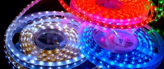
There are regular, single-color options, or multi-color RGB strips, for normal operation of which you will need a control device - a controller. All of them come ready to use, with a connector attached. All that remains is to plug the plug into the socket and place the tape in the planned location.
If desired, a regular LED strip can be converted to 12 V to operate from 5 V. However, this process requires some preparation, both theoretically and practically. Some users suggest assembling a 5 V to 12 V converter, but with this solution the permissible current drops from the original value of 500 mA to 250 mA. In addition, the very point of connecting the tape to USB is lost - then you can simply take a standard 12 V power supply and connect it to the network.
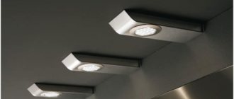
It is much easier to use ready-made luminaires based on SMD 2835 LEDs, containing 60 elements/meter of length. There are single and multi-color options, with varying degrees of protection. You can purchase them and connect them to the USB socket yourself by following some technical procedures. The advantage of this option will be a more precise adjustment of the length of the tape to the dimensions of the supporting surface, and the choice of the most suitable color shade.
https://youtube.com/watch?v=oAegvyHOySk
Backlight Features
To make the system correctly, you need to understand its features and understand how to connect it correctly. The main points do not differ from standard installation, but some require attention:
- Usually the length of the tape is short. This is due to the current limitations in the computer and laptop. It is easy to calculate the maximum length based on the total power of the LEDs.
- The tape can simply be glued to any surface, or it can be hidden in a niche or on the inside of the tabletop. It must be secured to prevent damage.
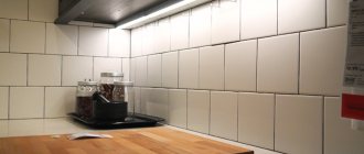
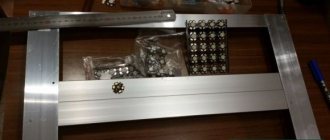
- If you need to get uniform light, it is better to use a special diffuser. There is an aluminum profile on sale, which is covered on one side with matte plastic; it diffuses the light and makes it uniform along the entire length of the box.
- The system most often does not have an outlet, since it is powered from the computer. There may be different options - connecting directly to the motherboard, connecting via a universal connector with a suitable voltage, or connecting via USB. All methods are described below.
- Due to the low electricity consumption, the computer is not subjected to high loads. The main thing is to follow the recommendations and not exceed a certain level of current consumption; to do this, accurately select the length of the connected tape.
- The backlight can work either constantly - turn on when you start the computer and turn off with it, or separately. For this, various switches and other devices are used.
Illumination of several zones on the table with connection to a computer.
This option is suitable for PCs as it does not pose any danger to the system. The tape hardly heats up during operation, so it does not increase the temperature when used inside the system unit. It is easy to attach, since there is always a self-adhesive layer on the back side; you just need to remove the protective coating. And the small width and the ability to cut into pieces of any length allow you to adjust the lighting to any conditions.
How to make a backlight for a PC with your own hands?
They operate in the following order:
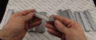
- Based on special marks, a fragment of a given length is cut from the tape,
- Treat the contact pads (lamellas) on it with alcohol.
- Using a puller or a utility knife, remove the ends of the wires from the insulation to a length of 5 mm.
- The exposed area is twisted into a tourniquet.
- Dip the stripped ends of the wires into rosin.
- Flux is applied to the contact pads of the LED strip using a toothpick.
- Take a small dose of solder with a heated soldering iron tip and transfer it to the lamella. To avoid burning it out, the contact time should be limited to 1 second.
- Solder tubercles are formed similarly on other contact pads of the connected tape.
- Brown deposits from the flux are removed with a napkin. If it has time to harden, this will require alcohol.
- Use wire cutters to shorten the bare ends of the wires so that they are equal in length to the lamellas. Otherwise, a short circuit may occur when the wires are bent.
- The core is placed on a tubercle of solder and pressed into it with a heated soldering iron. Contact duration is limited to 1 second.
- Before the solder hardens, ensure that the connection remains motionless. This takes a few seconds.
- Having soldered all the wires, clean the contact points from flux with a cloth soaked in alcohol.
- Place a heat shrink tube over the assembly and heat it.
- Cut off the SATA connector from the adapter.
- Strip the ends of the yellow and one black wires. The rest are trimmed and isolated.
- Heat shrink tubes are put on.
- Twist the wires from the LED strip and the connector in compliance with the polarity. Then the connection is soldered.
- Slide heat-shrinkable tubes over the contact points and heat them with a hair dryer, match or gas lighter.
- Insert the adapter plug into the Molex connector.
The RGB strip is connected in the same way. To avoid confusion, it is recommended to solder wires in insulation of different colors to the “cons”. Next, connect the cores from the Molex-SATA adapter to the RGB controller. On the other hand, wires from the LED module are connected to it.
The backlight assembled in this way lights up simultaneously with the computer startup. To be able to extinguish it during the day, a microswitch with a remote control function, for example, from a smartphone, is soldered into the gap of one of the wires.
The installation process is simplified if you purchase a piece of tape with wires already connected.
We make a direct connection
The LED strip can be connected to any computer via a USB connector.
Using a USB connector for connection is a fairly simple method that anyone can handle. To connect the tape via USB connector you need to do the following:
The power supply should be installed on the back of the monitor, securing it with double-sided tape;
Installing the power supply on the monitor
- We place ribbons along the edges of the monitor, connecting them to the power supply according to the above diagram;
- There is a USB connector coming from the unit. You can attach the USB connector to the unit with your own hands without any problems. To do this, cut off the plug from the power supply and attach a USB connector to it. It can be taken from any old cord. The main thing is that the USB connector is working;
- Next, you need to download the necessary drivers to your computer so that they support the operation of the assembled device.
That's it, the LED backlight is ready to work.
Characteristics of LED products
Before you start installing a tape to your computer (for example, one that plays with music), you need to decide on the characteristics. In fact, it is possible to connect any LED strip to a computer. But from all the variety, you need to choose the most suitable option for you, so that in the future it evokes only positive emotions. The choice of tape should be made according to the following characteristics:
Density of diodes on the tape
- single or multi-color glow;
- how many meters do you need;
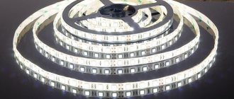
Note! LED strip is sold in reels of five meters. It will be enough for you to backlight your computer. But if you want to make a suspension in several places at once, then you can take more.
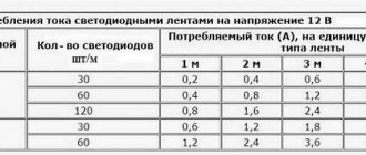
- density of LEDs on the strip. The correctness of calculation of the total power of the product, as well as the choice of power supply, depends on this parameter. The choice of power supply must be approached extremely responsibly. Typically this figure is 60 LEDs per meter. But the density of diodes on the tape can be 30 or 120 pieces per meter;
- waterproof class. To backlight your computer, you can use products with a low moisture resistance class (for example, 20IP).
Before connecting the selected LED products, let's consider the principles of connecting it to the power supply.
Main selection criteria
To select a power supply for an LED strip, you need to pay attention to the following key characteristics of this device:
- output voltage value - it must necessarily correspond to the indicator of the lighting device;
- device power indicator - calculated using a special formula;
- level of protection;
- availability of additional functions.
When choosing a power source, you also need to consider its cost. Models protected from moisture will cost more. Pricing is influenced by the conversion method of the device and its power indicators.
Conversion method
Operating principle of a switching power supply
Based on the conversion method, power supplies can be divided into 3 main types:
- linear;
- transformerless;
- pulsed.
Linear type power supplies were invented back in the last century. They were actively used until the early 2000s, before the appearance of pulsed devices on the market. Now they are practically not used.
Transformerless models are unsuitable for powering LED lamps. They have a complex design - the 220V voltage in them is reduced through an RC circuit with subsequent stabilization.
The main serious disadvantage is that the unit cannot be turned on without load. Otherwise, the power transistor may fail. On modern models, this problem was solved using feedback. As a result, at idle, the output voltage does not exceed the permissible limits.
Cooling
Depending on the cooling system used, power supplies are divided into 2 types:
- Active cooling – the device is equipped with an internal fan that is responsible for cooling efficiency. This design makes it possible to interact with fairly high powers. In this case, the fan may hum and needs to be cleaned periodically, since dust gets inside the case with the air flow.
- Passive cooling – the device is not equipped with a fan (natural cooling). Such power supplies are very compact, but are only suitable for domestic use, as they are designed for light loads.
Execution
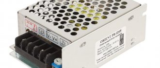
Compact power supply for LED strip
Based on the type of design, power supplies are divided into the following designs:
- Small-sized plastic case. This device is similar in appearance to laptop power supplies and has a collapsible plastic casing. Models of this class operate stably and are the best option for use in dry rooms.
- Sealed aluminum housing. The design features, tightness and strength of the material used allow the use of such an LED block in rooms with high humidity. It is resistant to moisture and has a long service life.
- Metal body with ventilation holes. Such devices are not protected from external influences, so they are mounted in special closed boxes. The open-type housing makes it possible to quickly reconfigure the unit.
Output voltage
This characteristic determines to what voltage rating the power source converts the original 220V mains voltage. Typically these are 12V and 24V DC or AC. The most common are 12V LED strips with constant voltage. Accordingly, they require a power supply marked DC12V.
Power
LED consumption
In some situations, there is simply no need to calculate the power of the power source. For example, if you need to connect 1 meter of SMD LED strip with a 12V power supply, any unit with a constant output voltage of 12V will do. If a more powerful load is expected, you will need to use the calculation formula.
You can select the power of the power source based on the maximum length of the LED strip and the consumption rate of 1 meter of the product. To facilitate this task, manufacturers specify the requirements for the power source in the instructions for the LED strip.
Additional functions
Power supply with remote control
In addition to the main characteristics, when choosing power supplies, you need to pay attention to the presence of additional functions in them:
- may be trivial and solely provide nutrition;
- more functional models have a built-in dimmer;
- Some devices are equipped with an infrared sensor or radio channel for control using a remote control.
No special connectors required
Computer power supply
In addition, you can connect the tape to the computer's power supply. All laptops today are equipped with such elements. Therefore, problems with installation in this situation should also not arise, if, of course, you take into account all the nuances of this connection method.
Here it is necessary to remember that all power supplies have their own standard set of operating voltages and differ in the permissible load power. In this situation, the output voltage for each existing wire of the power supply will vary depending on the color:
- orange +3.3 V;
- yellow +12.0 V;
- red +5.0 V;
- blue +5.0 V SB;
- blue -12.0 V;
- black GND.
These types of devices usually have labels with a table printed on them. It indicates the critical power, as well as the maximum load current for various voltage parameters.
Power table for power supply
In this regard, if the power supply is designed for a load of 400 W, then in reality it will have a current of 16 A in a voltage circuit of +12 V. This is quite enough to power an LED strip. Another nuance is that you need to consider its forced inclusion. The power supply in normal situations is activated by a signal from the motherboard. To activate it, you need to close pins 16 and 17, green and black, respectively. This must be done when turning on the power supply separately. To turn on the power to the LED source, use the yellow and black wire in the four-pin connector. In all other respects, the connection technique will be similar to the above-described options for connecting LED products to the converter. The main thing here is to strictly follow the lights and wires and determine the power of the converter.
Features of installation of monochrome light strips
Monochrome LED strips can have different shades, but the most common are those with a white glow, which, in turn, are divided by temperature conditions. For example, stripes with warm white light, closer in shade to incandescent lamps. This pleasant soft glow of a slightly yellowish tint is used for bedrooms, living rooms and children's rooms. If we talk about cold light, then this is most suitable for office premises.
PHOTO: designmyhome.ru Monochrome white tape in the interior looks pretty good
To connect a monochrome LED strip, only 2 contacts are required: plus and minus. Their installation is much simpler than RGB, however, the effect created by the operation of such a strip cannot be called unusual. Let's try to take a closer look at how a monochrome LED strip is connected.
Instructions for connecting a monochrome light strip
To make the step-by-step installation instructions easier for the reader to understand, we will illustrate all the steps performed with photo examples.
PHOTO: yastroyu.ru Low-power tape can be used as a backlight
Let's consider the simplest option, when all equipment is purchased simultaneously as a set. In this case, you will not need a soldering iron or additional connectors. All necessary plugs are already installed on the equipment.
First, let's look at what the kit is. This:
- LED strip 5 m long;
- dimmer with remote control for monochrome tape;
- power supply (in our case, its power is 6 W).
PHOTO: youtube.comKit for arranging lighting: tape, dimmer, power supply
After unpacking, you need to connect the LED strip to the dimmer, and then to the power supply. This is extremely easy to do; you just need to insert the plugs into the appropriate sockets.
PHOTO: youtube.com Connecting all elements of the circuit - now you can connect the power supply to the network
The LED backlight is turned on and off using the remote control. To do this, it has On and Off buttons.
PHOTO: youtube.comButtons for turning the LED strip on and off
Additional buttons, in our case orange-brown, adjust the intensity of blinking of the strip LEDs from the slowest (top) to the fastest (bottom). This option can create the necessary atmosphere during any celebration or dance.
PHOTO: youtube.comButtons for adjusting the intensity of the strobe mode
Also on the remote control you can find buttons to enable other modes, such as cyclic slow or accelerated fading. If you need to manually dim the lighting intensity a little, then there are keys at the top for these purposes. This, in fact, is the dimmer itself.
PHOTO: youtube.comManual dimming buttons on the remote control
Connecting two or more monochrome tapes
There is no particular difference in connecting additional tapes. However, there are a couple of nuances that should not be ignored. Firstly, LED strips cannot be connected in series, making strips of them more than five meters long. Such actions will lead to overheating and burnout of the tracks located closer to the power supply due to the increased load on them. Therefore, only parallel connection is suitable here.
PHOTO: carnovato.ru Monochrome tape switching diagram
Secondly, the power supply must have an output power corresponding to all LED strips connected to it. Ideally, the output power of the rectifier should exceed the consumed power by 30%. Otherwise, the power supply will overheat and eventually fail.
USB pinout
Modern computers most often use USB version 2.0. They use 4 wires, two of which carry data and the other pair carry the plus and minus 5V power supply. In standard units, the plus wire is red and the minus wire is black. The contacts in a regular, flat socket (USB type A) are arranged in such a way that the data wires run in the center, and the power supply runs along the edges.
Important! For mini USB sockets of both types, the placement will be the same, and for USB type B, which are used to connect printers or other peripherals, the power is located on pins 1 and 4, located on the right, one above the other (if the beveled edges are on top). A continuity test using a tester will help you determine more accurately where the plus and minus are. When connecting, it is necessary to take into account the location of the contacts, since you will have to solder the plug, where everything is located in a mirror order.
How to choose a ribbon
First you need to choose the right tape. An important factor when choosing is the purpose for which the backlight is installed. The tapes vary depending on the number of light bulbs located on one meter of tape. There are 30, 60, 120 and 240. The more bulbs, the brighter the light.
Next, you need to decide on the place where the tape will be located. Like any electrical device, it is afraid of moisture. But there are several types of tapes adapted to aggressive environmental influences. This can be found out by reading the label. IP20 is practically not protected. It should not be placed above the sink in the kitchen, bathroom or outdoors. Rather, she will have to illuminate bookshelves or paintings in the interior. IP65 is protected enough for use in the kitchen or bathroom. It also works great with outdoor lighting. IP68 is an absolutely protected tape that is easily suitable even for lighting swimming pools.
For further operation of the tape, you need to understand what kind of backlight is needed - monochrome or multi-colored, warm or cold
And, of course, pay attention to the size of the illuminated surface. All this should be taken into account when deciding on the purpose of the tape.
Application area
Thanks to its versatility and the ability to twist the tape into any arbitrary geometric shape, it has found its wide application in façade lighting, billboard illumination, as a holiday garland and decoration, and finally simply as the most compact and economical household lighting device.
It is actively used to organize lighting for aquariums, as well as lighting in the kitchen and in suspended ceilings, where, due to the extremely low degree of heating of such lamps, this is practically the only option for lighting.
Connecting LED strip to 220V network diagram
After choosing a power source, you need to connect the LED strip to this source.
1) Scheme: one power supply - one standard length tape
Typically, a standard LED strip is sold wound on a 5-meter reel. At its outer end there are short wires for connection. If there are no wires, then you need to solder them yourself. To do this, we take stranded wires of different colors (red - “+”, black - “-”), measure them along the length so that they can reach the power supply and strip them on both sides.
Using rosin and tin, we tin the wires and solder them to the tape tracks. This procedure must be performed with a low-power soldering iron and as quickly as possible, so as not to damage the LEDs with increased temperature.
It is advisable to install NShVI lugs on the free ends of the wires. With their help, you can achieve better contact with the terminals in the power supply. Here it is worth considering that to crimp the wire into the lug, a special tool is needed, which is used by electricians.
Soldering areas must be properly insulated using heat-shrinkable tubing. Next, the LED strip must be connected to the power supply.
2) A circuit with one power supply and two tapes (the power of the unit is designed for such a load).
Consider the following option: you need to install and connect an 8-meter long LED strip. It is very difficult to find a solid 8-meter piece, because... the standard size is only 5 meters.
In this case, there is only one way out - leave one piece 5 meters, and cut 3 meters from the second and connect them. To do this, you need to find a line along which to cut the tape with ordinary scissors. Next, you need to close the broken circuit with wires using soldering (this technology was given above).
After the wires are soldered and both pieces of the LED strip are ready, you can begin connecting.
There are options when it is necessary to connect a large number of LED strips to one power supply, which are located at different distances from it (for example, lighting a store window or simultaneous lighting of several pictures hanging at different distances).
To do this, it is not necessary to pull wires from each section to the power supply. You can lay one main line and connect LED strips directly to it.
Errors when connecting LED strip
The article discussed how to connect a standard LED strip to a network (usually it is 5 meters long). Often, two or more of them need to be connected. Here, most people make the main mistake; they simply connect the two ends of the tape directly and it turns out to be one 10-meter tape. This turns out to be an incorrect connection diagram and it is absolutely forbidden to do this.
The problem lies in the fact that the connection diagram for the LED strip was chosen incorrectly, and the wires connecting the diodes are of a very thin cross-section, which are designed exclusively for one product. By connecting several tapes in series, the resistance increases significantly.
This leads to the fact that the second and subsequent parts will burn much dimmer. In addition, a significantly increased current from the rated current will flow through the first connected strip, therefore, heat transfer will increase and the LEDs will fail faster.
As has been proven more than once, such a connection reduces the service life of the tape by several times. Therefore, try to use the correct connection diagram.
Why do this
If you need to illuminate the space around your computer, you shouldn’t waste money and take up space with a lamp. You can get by with a piece of LED strip and the result will be no worse than the finished version. This solution is also good because it consumes a minimum of energy, this is the most economical backlight today.
Lighting using LED strip serves different purposes. Most often used like this:
- To illuminate the work area near the computer. In this case, the tape needs to be placed higher so that it covers the entire table.
- Soft illumination of the space around the computer. It looks especially impressive if the monitor is mounted on the wall and the LEDs are located in the back. In this case, it is better to use a single-color option.
- System unit backlight. If the inside is top quality and one of the walls is transparent, you can highlight the space around the perimeter. Or replace one partition with plexiglass yourself and decorate your computer effectively.
- Illuminated keyboard for comfortable operation. There is not enough light from the monitor, so you can add a small piece of tape and illuminate the space without creating excess light.
- Decorative lighting for a table or interior elements located near the computer. For example, you can glue LEDs along the end of the tabletop or in its lower part. Or make a strip on the wall so as not to turn on the general light while playing games or watching movies.
Option for lighting the back of the monitor.
This method is good because to illuminate the space around the computer you do not need to stretch wires, of which there are already so many. And to connect, you don’t need an outlet, which is also often a problem, since you need to power many devices. An additional advantage is the long service life; the backlight works normally for at least 10 years.
How to connect an LED strip via USB
Using LEDs, you can easily illuminate the keyboard of a laptop or computer. In order to connect the LED strip to the laptop itself, a USB port is usually used. To do this, you need to purchase or find a working used USB plug.
The connection should be made via a limiting resistor. The resistance of the resistor is equal to the ratio of the difference between the supply voltage from the USB port (5V) and the direct voltage of the LED (depending on the color of the light) to the rated operating current of the LED.
To connect you need:
- Shorten the positive lead of the LED using wire cutters and solder a resistor to it.
- Connect the positive wire to the resistor, which will lead to the plug, and the negative wire to the LED.
- Cover the resistor itself and its connection with the LED contacts with heat-shrink tubing.
- Solder the connecting cord of two wires to the terminals of the USB plug, observing the polarity.
- Assemble the plug;
- Plug the tape into the USB connector and check its functionality.
In this case, the positive cable coming from the resistor is connected to the first terminal on the plug (+5V). The negative coming from the LED is connected to the fourth terminal (GND). To give the LED strip a more attractive look, you can put a heat-shrink tube on it. Mounting the LEDs on the keyboard can be done using adhesive double-sided tape.
Materials and tools required for work
To create and connect a USB LED strip you may need:
- the tape itself;
- wire or separate USB plug for soldering (best option);
- soldering iron and solder, ideally a soldering station with adjustable temperature and smoke exhaust;
- scissors, knife or other tool for removing insulation;
- tester or multimeter;
- connecting wires;
- current-limiting resistor (the value is calculated based on the operating voltage of the LED);
- screwdriver, pliers (just in case).
Materials for fastening the tape are deliberately not included in this list, since different installation methods are used for each case.
Disadvantages and advantages
A traditional power supply has several disadvantages that are not obvious at first glance:
firstly, it needs to be selected correctly and the corresponding power calculated
An error can lead to the fact that it will either burn out, or the tape will shine dimly without ever reaching full brightness.
complex connection diagram
This especially applies to lighting with additional amplifiers, controllers, etc.
a bunch of wires that need to be pulled from the power supply across the room to the connection point to the tape
Plus, do not forget about the 220V wires - from the distribution box or switch, which must be used to connect the power source itself.
the need for nearby AC voltage 220V
dimensions and dimensions
If this is ceiling lighting, then a constant headache becomes the question of where to hide this not at all miniature-sized box. Often you have to make a special niche.
It is based on these shortcomings that many people think about connecting LED backlighting via batteries. The advantages of this solution immediately emerge:
This LED strip can be used to illuminate even those rooms where there is no 220V voltage (garage, barn, cottage without light)
This creates convenient and safe lighting in the kitchen (especially the work surface of the countertop)
immediately eliminating the need to lay tens of meters of unnecessary wiring
Well, you no longer need to rack your brains about where to hide this big, heavy block
Conditions for using battery-powered LED lighting
However, this connection of the LED strip has its limitations. And this does not apply everywhere and not always.
The main disadvantage is the short length and low power.
With a long LED strip, for example, illuminating the entire perimeter of a house or a large room, it is still necessary to use a regular power supply with a traditional mains voltage of 220V.
So where can battery powered LED strips be used?
What kind of lighting do you prefer?
Built-in Chandelier
These can be either closets in the bedroom (with clothes and shoes) or in the kitchen (with dishes and various kitchen utensils).
Such lighting will no longer spoil the appearance of the canvas with ugly threads, but will only emphasize its beauty.
Here the main advantage of battery-powered lighting is completely evident - autonomy and independence from alternating mains voltage.
- temporary lighting of a room in case of an accident and complete lack of power supply in a house or apartment
Just remember to use a waterproof and sealed LED strip with IP 55.65 protection in this case.
You can independently integrate application options, depending on your fantasies and needs.
Connection
LEDs are powered by direct current; a diode bridge (rectifier) is used to convert AC to DC for 220V strips, and a power supply is needed to operate low-voltage options.
The DC-12V power supply is connected to phase and neutral from a 220 V network; this cable is mounted in a terminal block and clamped with a screw. The terminals are labeled L and N. The tape is connected to the V+ and V- terminals.
If you have RGB devices, a controller is connected to the V+ and V- terminals of the power supply, and an RGB LED strip is connected to it. In this case, the controller must produce the required current, preferably 20–25% higher than the tape consumption. This reserve is needed for reliability; if the length of the backlight is very large or you do not have the opportunity to buy a controller of the appropriate power, an amplifier will help. The voltage from the power supply and the signal from the output of the RGB controller are connected to its input. A similar signal is present on the contact patches of one of the ends of the nearest connected RGB installation. This signal is needed for the amplifier to duplicate the lighting circuit of the room, amplify it with the help of an additional power source, and at its output generate the necessary voltages and currents for the next sections of the tape.
Connectors
For novice electricians, quick installation or repair, connectors for LED strip are best suited. This is a terminal for installation and connection, consisting of a plastic opening housing and spring-loaded contacts. In order to make the connection, you need to open the case, insert the tape with the contact spots to the contacts and close the case. A two-wire connector usually has two wires coming out of it, black and red.
They come in several types:
- Connector – wire for connecting to the power supply.
- Connector-connector with wire - for joining tapes.
- Rigid connector – for connecting tapes without a gap between them.
In this case, the connectors differ in the number of wires and contacts:
- Two-wire – for mounting single-color tape.
- Four-wire – for multi-color tape.
Advantages:
- Quick assembly.
- Convenient to use for repairs.
Flaws:
- Not always available in stores.
- Still, they have their own price, which increases the overall cost of the structure.
- Contacts may oxidize and lose elasticity.
Soldering
To connect using soldering, you need to have some experience in electrical work and a little more tools and materials:
- Soldering iron.
- Rosin, or better yet liquid flux, for example, LTI or SKF.
- Solder such as POS-61.
First, prepare the place for soldering. In order for the solder to stick well, you need to remove oxides from the contacts. To do this, cut the tape where you are going to solder. Then, using a toothpick, a wooden part of a match or a stationery eraser, clean out the spots; fine sandpaper will also do.
Now coat them with flux if it is liquid, and if using rosin, take a little on the soldering iron tip and cover the contact. Add solder to the contact, it will become tinned. In other words, a shiny layer should appear on its surface - this is a sign that tinning was successful. Next you need to solder a piece of wire tinned in the same way.
Power reserve factor
Do not use a power reserve factor less than 30%. Why is it needed at all, you ask?
It is necessary so that the power supply does not work at the limit of its capabilities. If you select a unit strictly according to the power of the tape, it will not work for long. And only if it is a quality product.
In this case, the heating of the case will be consistently 60-70 degrees. And what can we say about the internal elements of the circuit!
In this case, the appearance of extraneous sounds is quite possible.
A normal unit (without a fan) should not make any sounds at all - neither whistle nor crackle.
Also, if overheating occurs, defective soldering may occur. Often, this is the most common cause of device failure.
The terminals of the elements that are not tinned oxidize over time and the contact simply disappears. It can be difficult for ordinary people not involved in radio engineering to find such a malfunction.
And they just throw the block in the trash. Although to fix it, all you had to do was to thoroughly solder one of the contacts.
What should you consider when choosing a power supply?
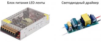
To connect an LED strip, you need a power supply or driver. These are different devices.
The driver produces a stabilized current. For example, 300 mA. And if you connect a strip that is too short, the voltage will become higher than the rated voltage and the diodes will burn out. And if it’s too long, they will shine dimly. Therefore, only the lighting equipment for which this adapter is designed is connected via the driver. Help: srivers are used in finished products, such as light bulbs and garlands.
Power unit. It is voltage adjusted. This means that we will get exactly 12 V at the output, regardless of power consumption. Power supplies are universal and easier to select than drivers. There are a few things to consider.
Total belt power
Unit of measurement – W/m. It depends on 2 quantities.
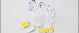
- LED type. The dimmest tapes are used for decorative purposes and are equipped with type 3528 diodes. They can highlight the contours of objects. And for bright lighting you need diodes of types 5050 (the most common) and 2535.
- The number of LEDs on one meter of strip is 30, 60 or 120.
Transformer ventilation
The power supply gets hot during operation and needs to be cooled. This is done in several ways.
- Models with active cooling are equipped with a cooler that drives air flow inside the case. Their advantages are greater power and smaller size, but their disadvantages are that the cooler is noisy and wears out over time. Such a system is needed when a tape of 800 W or more is connected.
- Adapters with passive cooling are more often used in domestic environments. They are silent, but take up a little more space. Yes, and it must be positioned so that there is an influx of fresh air. But they are more reliable because there are no moving parts. And better protected from bad weather.
Power adapters vary in their degree of protection.
- Open. The simplest and cheapest models, but also the most “delicate”. They are used only in indoor conditions, where there is no dust and low humidity.
- Semi-hermetic. Protected from the light vagaries of nature. Coarse dust and water splashes are not a problem for them, but constant humidity will quickly “kill” the adapter. On the street they need to be hidden under a canopy, or better yet, in an installation box. Degree of protection – IP54.
- Sealed. Dust and moisture will not penetrate through the protected housing. They are suitable for both street lighting and wet environments such as bathrooms and swimming pools. Degree of protection – IP65 or IP68 (*6 – complete protection from dust, *5 – protection from water jets, *8 – the device can withstand immersion in water).
To better understand the degrees of protection, use the table. By the way, it is suitable for all electronics.
The internal structure of all these adapters is the same. The output voltage for powering the strip is 24 Volts, 12 V or 5 V. The diode strip operates on direct current, and therefore cannot be connected to an indirect network. Although some people do this by mistake. The consequences are that the tape burns out and a fire may break out.
With ballast element
Connecting an LED strip to a 220 V network without a power supply is possible, but not advisable for safety reasons. Each point of the circuit will be under full mains voltage, so all manipulations must be performed with the tape completely turned off. But if safer options are not available, you can connect to the network through a resistor, which will absorb the excess voltage. Its rating is chosen so that at operating current (determined by the power of the lamp), the difference between the mains voltage and the rated voltage of the strip drops:
Rb=(Unetwork-Unom)/(Inom), where:
- Rb – ballast resistance value;
- Umains – mains voltage;
- Unom – rated voltage of the tape;
- Inom – rated current of the tape, calculated by the formula Rud*L / Unom.
If you set the values of the nominal voltage of the tape is 5 volts, the power of 1 meter of tape is 10 W and the total length is 5 m, you can calculate the value of Rb:
Rb=(310-5)/((10*5)/5)=305/10=30.5 Ohm. You can take the nearest standard value of 33 Ohms. At first glance, such a connection is much cheaper and simpler than with a power supply.
Connecting the tape through a quenching resistor.
In fact, everything is not so rosy. First you need to calculate the power dissipated by the ballast as the current multiplied by the voltage (here we take the effective voltage value of 220 V):
Rb=Inom*220V = 10A*220V=2200 W. It is difficult to find a resistor of such power, and its dimensions will be appropriate. And with increasing power of the canvas, the calculated resistance will fall, and the dissipated (wasted!) power will increase, so this method is applicable only for low-power lamps. This problem can be circumvented by using a capacitor instead of a resistor as a ballast. Its capacity is calculated using the following formula:
С=4.45 (Unetwork-Unom)/(Inom), where С is the capacitance in μF.
Using a capacitor as ballast.
The capacitor must be designed for a voltage of at least 400 V, and two resistors must be added to the circuit:
- R1 – with a resistance of several hundred kiloohms to discharge the capacitor after switching off;
- R2 – to limit the charging current at the moment of switching on, its nominal value can be several tens of Ohms.
But this problem is not the only one:
- Issues with electrical safety when operating tapes with such a connection were mentioned. Therefore, only a tape in a silicone shell can be powered in this way, and the joints must be carefully insulated. And it would be a completely bad idea to use such a connection in wet rooms (swimming pools, bathhouses, aquariums).
- The calculation is only valid for a specific tape of a given length. For any replacement or change in the length of the canvas, the ballast must be recalculated.
- The network voltage in normal mode can deviate within 5%, the maximum allowable is 10%. Also, the accuracy of the most common resistors is 10%. Taking into account the spread of the parameters of the tapes relative to the declared ones, the voltage on the tape (and the current through the LEDs) may differ significantly from the calculated ones, even if the calculations are refined with actual measurements - simply due to fluctuations in the network voltage. The result may be, on the one hand, a decrease in the brightness of the glow, and on the other, failure of the lamp due to overcurrent. This problem manifests itself more clearly the lower the supply voltage of the tape. When using a capacitor, the problem only gets worse, because the range of capacitance values is rarer than the range of resistances, and the actual accuracy is lower.
- When using a dimmer to regulate the brightness or a controller to control the glow color of RGB strips, the current through the LEDs will change, and at the same time the voltage drop across the ballast will change, which will also aggravate the instability of the voltage drop across the strip synchronously with the change in current. Therefore, the use of devices to regulate radiation intensity is excluded.
Due to the combination of problems, such a connection should be used only if it is completely impossible to use a power supply for the appropriate voltage.
Parallel connection of curtains with individual ballast.
If several pieces of fabric with a total length of more than 1 meter are used, they must be connected in parallel. Otherwise, the tape conductors will not be able to withstand the total current of the lighting system. It’s even better to calculate the ballast for each section separately. If replacement is necessary, only the fabric being replaced will be subject to recalculation. The diode bridge must be able to withstand the total current of all sections of the tape with a reserve.
Voltage converter 5V → 12V
When using a specialized PWM controller, for example LM2577, a minimum number of elements will be required. Its cost is low, and the assembled device starts working immediately, without additional configuration.
Converter circuit:
The simplest voltage converter 5 - 12V
What you need to have:
- PWM controller chip LM2577;
- several radioelements according to the circuit diagram;
- detachable USB connector;
- connecting wires.
This circuit is universal and allows you to obtain an output voltage in a wide range. Resistors R1 and R2 are responsible for the voltage level:
Uout = 1.23 * (1 + R1 / R2)
A little more detail about the element base and operation of the circuit. The circuit is a pulse-width converter in a standard microcircuit connection as shown in the technical documentation. Electrolytic capacitors at the power input and output are designed to smooth out DC voltage ripples. Their capacity is not critical. The main thing is that it is no less than indicated on the diagram. The operating voltage of electrolytic capacitors must be greater than the maximum used, that is, in our case, at least 20V.
The resistor and capacitor connected to pin 1 of the microcircuit are the frequency-setting circuit. Here the denominations must be strictly observed.
The same applies to the inductance between pins 4 and 5. The coil inductance value should be 100 µH. No more and no less.
Specific requirements apply to the diode. This circuit uses a high-frequency Schottky diode. Diodes of this type have high performance, and most importantly, a low voltage drop across the junction. Using a conventional high-frequency rectifier diode, we obtain strong drops in the output voltage when the load current consumption changes. The diode brand can be any, since this circuit uses low voltage and current values. The main condition is the use of a Schottky diode.
Detachable USB plug
To begin, wire up the USB connector. The socket has four contacts. The two extreme ones are the ones we need. In order not to be confused with the location of the front and back sides, it is easier to determine the polarity with any voltmeter by plugging the plug into any free socket. Label the positive terminal with something.
The circuit is assembled on a printed circuit board made of foil fiberglass. The assembled converter looks like this:
Converter assembly
As you can see, connecting an LED strip via USB yourself is not so difficult. The most important thing when connecting a USB LED strip is to correctly install the radio elements.
Remember, an LED strip operating from a USB port must have a current consumption of no more than 200 mA.
How to choose a ribbon
First you need to choose the right tape. An important factor when choosing is the purpose for which the backlight is installed. The tapes vary depending on the number of light bulbs located on one meter of tape. There are 30, 60, 120 and 240. The more bulbs, the brighter the light.
Next, you need to decide on the place where the tape will be located. Like any electrical device, it is afraid of moisture. But there are several types of tapes adapted to aggressive environmental influences. This can be found out by reading the label. IP20 is practically not protected. It should not be placed above the sink in the kitchen, bathroom or outdoors. Rather, she will have to illuminate bookshelves or paintings in the interior. IP65 is protected enough for use in the kitchen or bathroom. It also works great with outdoor lighting. IP68 is an absolutely protected tape that is easily suitable even for lighting swimming pools.
For further operation of the tape, you need to understand what kind of backlight is needed - monochrome or multi-colored, warm or cold
And, of course, pay attention to the size of the illuminated surface. All this should be taken into account when deciding on the purpose of the tape.