If you skip the details and explanations, the circuit for adjusting the brightness of the LEDs will appear in its simplest form. This control is different from the PWM method, which we will look at a little later. So, an elementary regulator will include only four elements:
- power unit;
- stabilizer;
- variable resistor;
- directly the light bulb.
Both the resistor and the stabilizer can be purchased at any radio store. They are connected exactly as shown in the diagram. Differences may lie in the individual parameters of each element and in the method of connecting the stabilizer and resistor (with wires or soldering directly).
Having assembled such a circuit with your own hands in a few minutes, you can make sure that by changing the resistance, that is, by rotating the resistor knob, you will adjust the brightness of the lamp.
In an illustrative example, the battery is taken at 12 Volts, the resistor is 1 kOhm, and the stabilizer is used on the most common Lm317 microcircuit. The good thing about the circuit is that it helps us take our first steps in radio electronics. This is an analog way to control brightness. However, it is not suitable for devices that require finer adjustments.
Conventional LEDs
An LED is the simplest indicator that can be used to debug code: it can be turned on when a condition is triggered or simply wink. But first you need to connect it.
LED connection
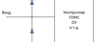
An LED is a device that is powered by current, not voltage. What does it mean? The brightness of an LED depends on the current that passes through it. It would seem that knowledge of Ohm's law from the first lesson in the section is enough, but this is not so!
- The LED in the circuit cannot be replaced with a “resistor”, because it behaves differently, nonlinearly.
- The LED is polarized, that is, if it is connected incorrectly, it will not light up.
- The LED has a maximum current characteristic that it can operate at. For regular 3 and 5mm LEDs this is typically 20mA.
- The LED has a voltage drop characteristic (Forward Voltage), the magnitude of this drop depends on the emitted color. The color is emitted by the crystal, the composition of which determines the color. For red LEDs the drop is ~2.5 volts, for blue, green and white LEDs ~3.5 volts. More accurate information can be found in the documentation for the specific LED. If there is no documentation, you can use this plate, here are the minimum values:
If you power the LED with a voltage below its drop voltage, then the brightness will not be maximum, and no drivers are needed here. That is, the red LED can be powered from a AA battery without any problems. At the same time, the crystal may degrade and the voltage will decrease, which will lead to an increase in current. But this is a rare case. As soon as we exceed the drop voltage, we need to stabilize the power supply, namely the current. In the simplest case, a resistor is installed for a conventional LED, the value of which must be calculated using the formula: R = (Vcc - Vdo) / I, where Vcc is the supply voltage, Vdo is the drop voltage (depending on the LED), I is the LED current, and R is the desired resistance of the resistor. Let's calculate the resistor for a regular 5 mm red LED when powered by 5 Volts at maximum brightness (2.5 V, 20 mA): (5-2.5)/0.02=125 Ohm. For blue and green colors you get 75 ohms. The brightness of an LED depends nonlinearly on current, so “by eye” at 10 mA the brightness will be the same as at 20 mA, and the resistance value can be increased. But you can’t reduce it, just as you can’t connect it without a resistor at all. In most tutorials and projects in general, a 220 ohm resistor is used for regular LEDs of all colors. With a 1 kOhm resistor, the LED will also glow, but noticeably dimmer. Thus, using a resistor, you can set the brightness of the LED in hardware. How to determine the plus ( anode ) and minus ( cathode ) of an LED? The plus leg is longer, the side of the minus leg is slightly cut off, and the electrode itself inside the LED is larger:
Flashing
Flashing an LED with Arduino is very simple: connect the cathode to GND, and the anode to the GPIO pin. Many people are sure that “analog” pins are just analog, but this is not the case: these are ordinary digital pins with the ability to digitize an analog signal. On the Nano board, pins A0-A5 are digital and analog at the same time, but A6 and A7 are analog, that is, they can only read an analog signal. So let's connect to A1, configure the pin as an output and flash!
void setup() { pinMode(A1, OUTPUT); } void loop() { digitalWrite(A1, HIGH); delay(500); digitalWrite(A1, LOW); delay(500); }
I talked about how to get rid of delay() in any code in this lesson. https://www.youtube.com/watch?v=uaiLcCd9Tnk
Flashing smoothly
How about smooth brightness control? Let's remember the lesson about the PWM signal and connect the LED to one of the PWM pins (on Nano these are D3, D5, D6, D9, D10, D11). Let's make a pin as an output and we can control the brightness using a PWM signal! Read the lesson about PWM signal. A simple example with several brightness levels:
void setup() { pinMode(3, OUTPUT); } void loop() { analogWrite(3, 10); delay(500); analogWrite(3, 100); delay(500); analogWrite(3, 150); delay(500); analogWrite(3, 200); delay(500); analogWrite(3, 255); delay(500); }
Let's connect a potentiometer to A0 and try to adjust the brightness with it:
void setup() { pinMode(3, OUTPUT); } void loop() { // analogRead(0) / 4 == 0... 255 analogWrite(3, analogRead(0) / 4); delay(100); }
As you can see, everything is very simple. Let's do one more interesting thing: let's try to smoothly turn on and off the LED, for which we will need a loop from the lesson about loops.
void setup() { pinMode(3, OUTPUT); } void loop() { for (int i = 0; i < 255; i++) { analogWrite(3, i); delay(20); } for (int i = 255; i > 0; i—) { analogWrite(3, i); delay(20); } }
Bad example! The smooth brightness change algorithm blocks code execution. Let's do it on an uptime timer.
void setup() { pinMode(3, OUTPUT); } uint32_t tmr; int val = 0; bool dir = true; void loop() { if (millis() - tmr >= 20) { tmr = millis(); if (dir) val++; // increase the brightness else val—; // decrease if (val >= 255 || val <= 0) dir = !dir; // expand analogWrite(3, val); } }
Now changing the brightness does not block the execution of the main loop, but the rest of the code should be written in the same way so as not to block calls to the brightness change function! Another option could be to interrupt the timer, see the lesson.
The LED will not blink very smoothly: the brightness will increase too sharply and will hardly change. This is due to the fact that the human eye perceives brightness nonlinearly, but we control it linearly. For a smoother feeling of brightness, correction according to the CRT gamma is used, which has been moved from this lesson to a separate lesson on blinking an LED according to the CRT gamma in the algorithms block. Be sure to study it!
One more point: if you connect the LED the other way around, to VCC, its brightness will be inverted: 255 will turn off the LED, and 0 will turn it on, because the current will flow in the other direction:
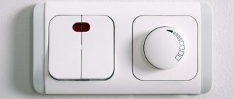
Ready-to-use dimmers
A regulator that is sold ready-made for LED lamps is called a dimmer. The frequency of the pulses created by them is high enough so that we do not feel flickering. Thanks to the PWM controller, smooth adjustment is possible, allowing you to achieve maximum brightness or dimming of the lamp.
By installing such a dimmer into the wall, you can use it like a regular switch. For exceptional convenience, the LED brightness control can be controlled by a radio remote control.
The ability of lamps based on LEDs to change their brightness opens up great opportunities for holding light shows and creating beautiful street lighting. And it becomes much more convenient to use a regular pocket flashlight if you can adjust the intensity of its glow.
LED strips
An LED strip is a chain of connected LEDs. They are connected for a reason; for example, a regular 12V strip consists of segments of 3 LEDs each. The segments are connected to each other in parallel, that is, each receives a common 12 Volts. Inside the segment, the LEDs are connected in series, and the current on them is limited by a common resistor (there can be two for more efficient heat dissipation): Thus, it is enough to simply apply 12V from the voltage source to the strip and it will glow. Simplicity and convenience come at the price of efficiency. Simple math: three white LEDs, each needs ~3.2V, for a total of 9.6V. We connect the tape to 12V and understand that 2.5V simply goes into heat on resistors. And this is in the best case if the resistor is selected so that the LED lights up at full brightness.
Connect to Arduino
Everything is very simple here: see the previous lesson on controlling a DC load. It can be controlled via a relay, transistor or solid state relay. We are most interested in smooth brightness control, so I will duplicate the circuit with a field-effect transistor:
Of course, you can use a Chinese mosfet module! By the way, the VCC pin does not need to be connected; it is not connected anywhere on the board.
Control
The transistor-connected strip is controlled in exactly the same way as the LED in the previous chapter , that is, all code examples with blinking, fade-out blinking, and potentiometer control apply to this circuit. We will talk about RGB and addressable LED strips in separate lessons.
Power and Power
The LED strip consumes a lot of current, so you need to make sure that the selected power supply, module or battery is up to the task. But be sure to read the lesson on Ohm's Law first! The power consumption of an LED strip depends on several factors:
- Brightness _ Maximum power will be consumed at maximum brightness.
- voltage (most often 12V). There are also 5, 24 and 220V tapes.
- Quality , type and color of LEDs: LEDs that look the same can consume different currents and shine with different brightness.
- length . The longer the tape, the more current it will consume.
- The density of the tape is measured in the number of LEDs per meter. There are from 30 to 120 pieces, the denser the more current will be consumed at the same length and the brighter the light.
The tape always has a power characteristic per linear meter (Watt/m); the maximum power of the tape when powered from the rated voltage is indicated. Chinese tapes generally have a slightly lower actual power (around 80%, sometimes better, sometimes worse). The power supply must be selected so that its power is greater than the power of the tape, i.e. with a margin of at least 20%.
- Example 1: you need to connect 4 meters of tape with a power of 14 Watts per meter, the tape can operate at maximum brightness. 14*4 == 56W, with a 20% margin it will be 56*1.2 ~ 70W, the nearest power supply on sale will most likely be 100W.
- Example 2: we take the same tape, but we know for sure that the brightness during operation will not be more than half. Then you can take a block at 70 / 2 == 35W.
Important points regarding current and connection:
- Connection : let's say we have 100W tapes connected. At 12 Volts it will be 8 Amps - quite a lot of current! The tape should be placed as close as possible to the power supply and connected with thick (2.5 sq. mm or thicker) wires. Also, when creating lighting, it makes sense to switch to 24V strips, because the current in the circuit will be less and you can use thinner wires: if the strip from the previous example were 24-Volt, the current would be about 4 Amps, which is no longer so “hot” .
- Power redundancy : The tape itself is a flexible printed circuit board, meaning the current flows through a thin layer of copper. When connecting a large length of tape, the current will be lost through the resistance of the tape itself, and the further away from the connection point, the weaker it will shine. If maximum brightness is required over a long length, you need to duplicate the power supply from the power supply with additional wires, or install additional power supplies along the strip. It is recommended to duplicate the power every 2 meters, because at this length the brightness drop becomes noticeable on almost all tapes.
- Cooling : LEDs are not 100% efficient, plus the current in them is limited by a resistor, and as a result, the tape gets quite hot. It is recommended to stick a bright and powerful tape on the heat sink (aluminum profile). This way it won’t peel off and will generally live much longer.
Kinds
There are a great variety of dimmers available. If desired, such a device can be selected to suit any tasks and needs. In this article we will briefly talk about only some popular types.
- Mini dimmers are compact in size and light in weight. In this case, they can be with push-button, touch or remote control.
- Dimmers with an audio input allow you not only to adjust the brightness of the light, but even to create a color music effect in automatic mode.
- Dimmers for RGB tape. RGB tape differs from conventional (monochrome) LED in its “multicolor”, that is, such a tape contains red, green and blue diodes, which allows you to create different color effects. Below is the simplest diagram for connecting an RGB tape to a 220 volt network.
Appearance
Connection diagram
Important Pages
- GyverKIT kit - a large Arduino starter kit of my design, sold in Russia
- Catalog of links to cheap Arduins, sensors, modules and other hardware from AliExpress from trusted sellers
- A selection of libraries for Arduino, the most interesting and useful, official and not so
- Complete documentation on the Arduino language, all built-in functions and macros, all available data types
- A collection of useful algorithms for writing sketches: code structure, timers, filters, data parsing
- Video lessons on Arduino programming from the “Arduino Engineer's Notes ” channel are some of the most detailed in RuNet
- Support the author for his work on the lessons
- Feedback - report an error in the lesson or suggest an addition to the text ( [email protected] )
5 / 5 ( 13 votes)
Main conclusions
It is impossible to measure the intensity of an LED at home. This indicator is rarely indicated in the labeling; to make the right choice, you need to know its dependence on the size of the crystal, the light flux and the angle of radiation.
The ability to change brightness (use dimming) is widely used in everyday life to save energy and install special lighting systems. The intensity of the glow can be reduced when watching television programs, while relaxing, for night lighting of children's rooms. Ease of use increases the ability to control dimming using a remote control or automatically (taking into account movement and time).
DIY dimmer
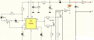
We have more or less figured out the dimmers for the LED strip. The time has come to find out how to make a dimmer with your own hands, and whether it is even possible. Since I don’t know your level of preparation, I’ll focus on a fairly simple scheme. It is made on an accessible element base, but performs the functions of a dimmer quite well and will fit into the body of a standard switch.
A simple dimmer circuit for an LED strip using the PWM adjustment method
A classic multivibrator with variable duty cycle is assembled on transistors VT1, VT3, and the right arm of the multivibrator is reinforced by transistor VT2, which forms a push-pull switch with VT3. The capacitances of capacitors C2 and C3 are chosen such that at any duty cycle the generator frequency is 14 kHz. This will eliminate flickering of the tape and its “ringing” at low brightness
The duty cycle is changed using variable resistor R3
This will eliminate flickering of the tape and its “ringing” at low brightness
The duty cycle is changed using variable resistor R3
The multivibrator is loaded onto a powerful switch made of field-effect (MOSFET) transistors VT4, VT5 connected in parallel. Diode VD1 protects the transistors from reverse induction voltage, which can occur in the SL supply wires if they are long enough.
The circuit uses field-effect transistors with an N-type channel. What if you find similar ones with a P-type channel? It's OK. There is no need to change the dimmer circuit itself, just swap the extreme terminals of the variable resistor R3 and change the connection circuit of VT4, VT5.
Variant of a dimmer on field-effect transistors with a P-type channel
This device allows you to adjust the brightness of the tape from 10 to 90%, which is not bad for such a simple scheme.
Now for the details. KT315 and KT361 are the most common transistors among radio amateurs, and they can be found in almost any domestically produced household equipment of the 90s. Even now in the KeTeshki store they cost a couple of rubles.
Field-effect transistors can be removed from any motherboard of a faulty PC. If the SL power does not exceed 35 W, then transistors VT4, VT5 can operate without a radiator. If the power is higher, then a radiator will, of course, be needed.
Interestingly, this circuit does not require a switch. When you turn the resistor R3 slider all the way to the left according to the diagram (brightness level below 10%), the generation will fail due to a strong imbalance of the multivibrator arms (R4 versus R3+R5). Transistors VT2, VT3 will “get stuck” in a position that reliably locks VT4, VT5. SL will go out.
What are the differences between dimmers?
If you are going to use a switch with brightness control, you first need to find out what they are.
And in general, can all LED lamps be dimmed? Dimmers differ according to the following criteria:
- By type of installation;
- on execution and method of management;
- according to the method of regulation.
Let's take a closer look at each of them.
By installation type
For outdoor installation – surface-mounted switch with dimmer for LED lamps. To install such a device, you do not need to drill a niche in the wall; it is simply mounted on top of the wall. It is very convenient to use in cases where the interior is not a priority or external wiring is installed.
For indoor installation - they will fit perfectly into any interior, such as this one.
For DIN rail mounting they are very specific and at first it may seem that they are not practical. However, this dimmer for LED lamps works with a remote control, and is hidden from prying eyes in the electrical panel.
By execution
According to the design, the light controller for LED and incandescent lamps can be:
- Rotary;
- rotary-push type;
- push-button;
- sensory;
Rotary is one of the simplest options for dimming an LED lamp; it looks unpretentious and has the simplest functionality.
The turn-and-push one looks almost the same as the rotary one. Thanks to its design, when you press it, the light turns on with the same brightness as it was set the last time you turned it on.
A push-button controller for LED lighting looks more technologically advanced and will fit seamlessly into a modern apartment. Like this switch with a dimmer for LED lamps.
Touch models can be completely different - from luminous circles to smooth single-color panels for adjusting the voltage of LED lamps.
According to the adjustment method
Dimmers vary not only in their design, but also in their operating principle. This applies specifically to AC dimmers.
The first type of dimmer is more common and cheaper, due to the simplicity of its circuit - a leading edge cutoff dimmer. A little further on, its operating principle and circuit will be discussed in detail; for comparison, take a look at the type of voltage at the output of such a regulator.
The graph shows that the remainder of the half-wave is supplied to the load, and its beginning is cut off. Due to the nature of the load switching on, interference is generated in the electrical networks, which interferes with the operation of televisions and other devices. A voltage of the set amplitude is applied to the lamp, and then it fades out when the sine wave passes through zero.
Can a leading edge dimmer be used for LED lamps? Can. LED lamps with a dimmer of this type will only be well adjustable if they were originally designed for this. This is evidenced by the symbols on its packaging. They are also called “dimmable”.
The second type works differently, creates less interference and works better with different light bulbs - this is a falling edge dimmer.
LED lamps with this type of dimmer adjust better, and its design better supports non-dimmable light sources. The only drawback is that these lamps can adjust their brightness not from “zero”, but within a certain range. At the same time, dimmable LED lamps are simply superbly adjustable.
A special word can be said about ready-made LED lamps with adjustable brightness. This is a separate class of lighting devices that do not require the installation of additional regulators, but have them in their design. Their adjustments are made using buttons on the case or from the remote control.
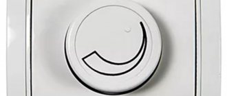
Turning
Correct selection and installation of the regulator will significantly increase its service life. The rotary version has a rotating knob, which, when installed in the extreme left position, turns off the lighting. Gradually turning the knob to the right increases the brightness of the lamp.
Key
The main components of the variator: triac, pulse formation unit, diac (dinistor). The key version is very similar in appearance to conventional two-key switches. Using the keys, you can turn the lighting device on and off, and also adjust the lighting power.
Turn-push
Additional parts of the variator: resistors and capacitors. The rotary-push version has a principle of operation similar to a rotary device, but to turn on the lighting system you need to “retract” the handle a little.
Neon light resolver
High voltage, high frequency transformers should be used for this light source. There is a dimmer on the body of these devices that allows you to regulate the high voltage. After purchasing this device, you can control the brightness of the LED sign. The operation of these dimmers is based on pulse width modulation.
Dimmer for neon lighting
Now you know the popular types of dimmers. Each specific type is designed for a specific light source. Therefore, the choice should be approached carefully. We hope this information was useful and interesting.
We recommend reading:
Types of devices by installation method
To solve various problems and simply to increase comfort, modern brightness controllers can be mounted in different places. In addition, this feature makes them more convenient to operate.
Dimmers are as follows:
- invoices;
- built-in;
- modular.
The easiest to install are surface-mounted devices, which are similar in shape and size to conventional switches and are quite capable of replacing them. Their installation procedure is also similar, and the control principle is similar.
The use of a radio signal allows control from any corner of the room, building, and, if necessary, from outside them
The main feature of all kinds of built-in dimmers is that they are mounted in a distribution box or a specially made niche. As evidenced by the very name of this variety.
Modular devices are designed for installation in electrical panels on DIN rails. This feature is due to the fact that they are large in size and high in power. Which in everyday life allows them to be used to control several supply lines at once.
The future user should remember that modern dimmers, regardless of the type of installation, are connected to or built into a circuit between the LED strip itself and its power supply.
That is, there cannot be another option, which must be taken into account for ease of installation and management. It is also common to see regulators divided according to the number of working channels and the protocol used.
Any built-in dimmer does not have high aesthetic properties, but its functionality is not inferior to its overhead counterparts
But, in most cases, this is of little interest to the ordinary user, since structurally complex models are rarely used in domestic conditions, small commercial and office premises due to their considerable cost.
At what price can you buy a dimmer for 220 V LED lamps
Nowadays, purchasing dimmers for LED lamps and strips is not a problem. They are sold in traditional specialty stores, markets and online. The variety of models is simply amazing and sometimes it makes it difficult to choose, but you can always choose what you need. As for the cost, the cost of dimmers ranges from 450 rubles to several thousand. It all depends on the model and type of device, its power, manufacturer and even the region where the dimmer is sold. In general, many factors influence pricing, but it is best to purchase an expensive device, but from a proven and reliable manufacturer.
Previous LightingSaving on replacement: do-it-yourself repair of LED lamps Next LightingDrivers for LEDs: types, purpose, connection
What lamps can be used?
Every potential owner of a dimmer should remember that only special LED lamps that can be dimmed can be used with it.
They can be easily identified by the inscription “Dimmable” or the corresponding sign on the packaging. This condition is mandatory, since the use of conventional LED lamps will only lead to their frequent flickering, and a smooth glow cannot be achieved; if the voltage does not correspond to the specified voltage, then they simply do not turn on.
Dimmers with combined control are more functional, since in addition to switching on/off and regulation, they can be programmed. They are also more convenient to use
In addition, this kind of experiment will lead to rapid wear of the LED lamp or the dimmer itself and further failure.