Calculation of loads according to RTM 36.18.32.4-92 (program)
Calculation of electrical loads is one of the main tasks of a design engineer. In this article I would like to talk about the calculation of electrical loads of industrial installations. When calculating the loads of industrial facilities, some features should be taken into account.
The calculation is performed according to RTM 36.18.32.4-92 (Guidelines for calculating electrical loads). This calculation method does not apply to electrical receivers with a sharply variable load schedule, industrial electric transport, residential and public buildings, as well as to electrical receivers with a known load schedule.
The following definitions are used in the calculation:
The installed power of one electrical unit (rn) is the power of the electrical receiver according to the passport.
Group installed active power (Pn) – the sum of the installed powers of all electrical receivers of the power panel.
Reactive power of one electrical unit (qn) – reactive power of one electrical receiver at rated active power.
Group reactive power (Qn) is the algebraic sum of the reactive powers of all electrical receivers of the power panel.
The utilization factor of an individual electrical receiver (ki) or a group of electrical equipment (Ki) is the ratio of the average active power of an individual electrical receiver (рс) or a group of electrical equipment (Рс) for the busiest shift to its nominal value (рн or Рн).
The effective number of electrical receivers (nе) is the number of electrical units of the same power homogeneous in operating mode, which determines the same design load values as a group of electrical units of different power.
Estimated active (Рр) and reactive (Qр) power is the power that corresponds to such a current load (Iр) and is equivalent to the actual time-varying load for the greatest possible thermal effect on an element of the power supply system.
Calculated power factor (Kp) – the ratio of the calculated active power (Рр) to the value (KiRn) of the electric power group.
Sequence of calculation of electrical loads of an industrial facility.
To begin with, I suggest downloading a program with ready-made tables and formulas made according to the F636-92 form. To prevent accidental deletion of formulas, cells with formulas are protected from editing.
To get the program, go to the MY PROGRAMS page.
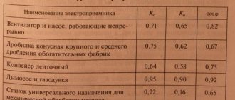
In the archive, in addition to the program, you will also find RTM 36.18.32.4-92.doc and M788-1069.xls (Reference data on the calculated coefficients of electrical loads).
This program allows you to calculate electrical loads of electrical installations up to 1000V. For clarity, cells that have a functional connection are highlighted in the same color.
Appearance of the table for calculating the ASU according to RTM 36.18.32.4-92
The first table is made for an input distribution device (IDU) or main switchboard. This table contains information on distribution boards, work and emergency lighting boards, as well as single electrical receivers connected directly from the ASU. Here we enter the total installed power of the shield (Pn), the group utilization factor (Ci) and the total power factor of the power shield. Only supply three-phase power. If there are single-phase power consumers, they should be converted to equivalent three-phase power.
If there are groups of single-phase EDs that are distributed across phases with unevenness of no more than 15% in relation to the total power of three-phase and single-phase EDs in the group, then the equivalent three-phase power will be equal to the sum of all single-phase receivers. Otherwise, the equivalent three-phase power should be taken at the most loaded phase multiplied by three (Req = 3Pa or 3Pb or 3Pc).
Calculation of phase loading unevenness
Calculation of distribution board loads is carried out in tables ShchS1-ShchS7. I think 7 tables are enough for distribution boards.
Appearance of the table for calculating the SchS according to RTM 36.18.32.4-92
When calculating power distribution boards, all three-phase electric power supply units are also entered into the tables. Single-phase electric motors are reduced to equivalent three-phase power. If there are receivers of the same type with the same power, utilization and power factor, they are combined into groups. After filling out all the electronic signatures, it is necessary to select the design load coefficient from Table 1 depending on the effective number of electrical receivers (ne) and the group utilization factor (Ki).
The design load factor for the ASU is selected according to Table 2.
If necessary, reactive power compensation should be performed. I have already written how to calculate the power of a capacitor installation. After this, it is necessary to recalculate the calculated current of the ASU taking into account reactive power compensation. To do this, in the cell instead of (Qр), you need to write the value of reactive power: Q=Qр- Qcond.installation. As a result, we obtain (Iр) taking into account reactive power compensation.
In the program you can also calculate the current of a single-phase electric motor.
In principle, if we record the calculated power (PP) of the panels on the ASU and take the group utilization factor (Ci) as 1, we will get the same result.
A separate post will be devoted to the calculation of public buildings. There are some peculiarities there.
I advise you to subscribe to new articles to find out about it as early as possible.
The calculated power of any group of electrical receivers cannot be less than the rated power of the most powerful electrical receiver in the group.
Also look at my article: Determination of conditional three-phase power created in a three-phase network by single-phase electric motors
See the conditions for receiving the program on the MY PROGRAMS page.
The modified program looks like this:
I recommend reading:
Calculation of response time of VA88 with MP211
Calculation of grounding system for lightning protection
Calculation of the required number of lamps at a given illumination
How much does a power supply project for an apartment or private house cost?
Calculation of maximum thermal load
Name of object: Grocery store
Content:
- Initial data
- Calculation of heat load for heating
- Calculation of heat load for hot water supply
- Technical conclusion
- List of normative, technical and special literature
- Complete information on calculating thermal loads
Calculation of heat load • Coordination with MOEK
Calculation of required power
This calculation will be needed to understand whether the amount of allocated electrical power for an apartment or house will be sufficient. To do this, you will need to calculate the maximum load by summing up the corresponding parameters of all consumer electrical installations. Moreover, it is necessary to take into account all household electrical appliances that can be turned on at the same time.
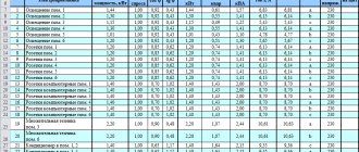
As a rule, all the necessary information is indicated on a sticker affixed to the equipment body or is given in the documentation. If the sticker has become unreadable and the technical data sheet has been lost, you can use the table that shows the typical active power of household equipment.
Table of approximate power consumption of various household appliances
Having calculated the total consumption, do not rush to consider the work completed; it is necessary to add a reserve, taking into account a possible increase in load over time. As a rule, the size of the reserve is set at 20-30% of the calculated parameters.
By adding these two values, we get a result that can be compared with the allowed power. If it turns out to be less than the calculated load, it makes sense to think about applying for an additional 1 kW or 3 kW. Details about adding additional kilowatts will be discussed below.
What are the dangers of exceeding the permitted power?
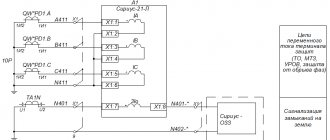
Currently, when it detects that the maximum load has been exceeded, the electric company introduces a consumption limitation mode. The basis for this is a violation of the obligations specified in the energy supply agreement. As a rule, limiting consumption is turning off the electric current. The algorithm for sending such a notification is shown in the figure.
Example of a consumer notice
After 10 days after sending the notice, the company disconnects the power supply. To avoid this, the consumer must eliminate the violation within ten days, and then contact the service provider to draw up the appropriate report. Electricity supply will be restored after the electric company pays the penalty in accordance with the contract.
More serious consequences may arise if, in addition to violating the amount of allocated energy, an accusation of uncontrolled electricity consumption is brought forward. The basis for this will be the removal of seals from the input machine. You can get more detailed information about the consequences of uncontrolled electricity consumption, electricity metering rules, etc. on our website.
Seal on the introductory machine (marked in red)
List of normative, technical and special literature
Heat consumption is calculated in accordance with and taking into account the requirements of the following documents:
- Methodological guidelines for determining the consumption of fuel, electricity and water for heat production by heating boiler houses of municipal heat and power enterprises (SUE Academy of Public Utilities named after K.D. Pamfilov, 2002);
- SNiP 23-01-99* “Building climatology”;
- Calculation of central heating systems (R.V. Shchekin, V.A. Berezovsky, V.A. Potapov, 1975);
- Designer's Handbook “Internal Sanitary Installations” (I.G. Staroverov, 1975);
- SP30.13330 SNiP 2.04.-85* “Internal water supply and sewerage of buildings.”
- “Technical regulations on the safety of buildings and structures.”
- SNiP 23-02-2003 “Thermal protection of buildings”
- SNiP 23-01-99* “Construction climatology”
- SP 23-101-2004 “Design of thermal protection of buildings”
- GOST R 54853-2011. Buildings and constructions. Method for determining the heat transfer resistance of enclosing structures using a heat meter
- GOST 26602.1-99 “Window and door blocks. Methods for determining heat transfer resistance"
- GOST 23166-99 “Window blocks. General technical conditions"
- GOST 30971-2002 “Mounting seams of junctions of window blocks to wall openings. General technical conditions"
- Federal Law of the Russian Federation of November 23, 2009 N 261-FZ “On energy saving and increasing energy efficiency, and on introducing amendments to certain legislative acts of the Russian Federation.”
- Order of the Ministry of Energy of Russia dated June 30, 2014 N 400 “On approval of the requirements for conducting an energy survey and its results and the rules for sending copies of the energy passport drawn up based on the results of the mandatory energy survey.”
View other heat load reports.
Annual consumption for the heating period
Qoyear = Qomax´ ((ti – tm)/(ti – to))´ 24´ Zo´ 10-6 = 5676.13 ´ [(18 +3.1)/(18 +28)] ´ 24 ´ 214 ´ 10-6= = 13.3722 Gcal/year, where:
tm = -3.1 °C – average outside air temperature for the calculation period;
ti = 18 °C – design temperature of internal air in the premises;
tо = -28 °С – design temperature of outside air;
24 hours – duration of operation of the heating system per day;
Zo = 214 days. – duration of operation of the heating system for the billing period.
Installed capacity for power plants
For power plants, the installed power is calculated by summing the power ratings of the individual generators and their associated motors. Almost always these values are identical. In cases of discrepancy, the calculation is carried out using a lower power.
As a result, at expensive stations with high fuel economy, the cost of electricity is extremely dependent on the consumption mode. Therefore, for large stations it is beneficial to use the installed capacity for a maximum of hours per year, and for small gas turbine plants with high fuel consumption, it is more expedient to switch them on during peak load hours, when the total operating time on an annual basis is small.
Design power for industrial facilities
The design capacity of an industrial enterprise depends on:
- type of product;
- technologies used;
- expected maximum load during the year;
- type of products;
- type of equipment and the degree of its adaptation to technology.
There are many calculation methods, all of them must have common properties:
- ease of calculation;
- versatility in determining loads for different levels of energy consumption and distribution;
- accuracy of results;
- ease of determining the indicators on which the method is based.
The main indicators are calculated using the same formulas, but with different correction factors.
For three-phase electric motors, the installed power is:
Р = Рн/(η x cos φ), where:
- Рн – nominal power indicator from the data sheet;
- η – efficiency of the electric motor;
- cos φ – power coefficient.
An increase in the allocated power, according to technical conditions, must be agreed upon with the energy supply organization. For this purpose, recalculations are carried out for input cables and protection devices based on the new installed power. But the decision to allocate depends on the availability of free capacity.
Initial data. Calculation of maximum thermal load
This calculation was carried out to determine the actual heat load for heating and hot water supply of non-residential premises.
| Customer | Grocery store |
| Address of the object | Moscow |
| Heat supply agreement | There is |
| Number of floors of the building | 17 floors |
| The floor on which the premises being examined are located | 1st floor |
| Floor height | 3.15 m. |
| Heating system | independent |
| Bottling type | lower |
| Temperature chart | 95/70 °C |
| Estimated temperature chart for the floors on which the premises are located | 95/70 °C |
| DHW | Centralized |
| Estimated indoor air temperature | 18 °C |
| Submitted technical documentation | 1. Copy of the heat supply contract 2. Copy of the floor plan. 3. A copy of the explication of the premises. 4. Certificate of headcount. |
| Room number | No. of the heating device on the plan | Photo of the heating device | Technical characteristics of the heating device |
1st floor | |||
| 11 | 1 | PURMO Plan Ventil Compact Length 700 mm | |
| 1 | 2 | PURMO Plan Ventil Compact Length 700 mm | |
| 6 | 3 | PURMO Plan Ventil Compact Length 1200 mm | |
| 4 | 4 | PURMO Plan Ventil Compact Length 1300 mm | |
| 3 | 5 | PURMO Plan Ventil Compact Length 1300 mm | |
Calculation of heat load for hot water supply
Probability of action of sanitary appliances.
P = (qhhr,ux U) / (qh0 x N x 3600) = (1.7 x 4) / (0.2 x 2 x 3600) = 0.00472,
where: qhhr,u = 1.7 l;
U = 4 people – number of personnel;
qh0 = 0.2 l/s;
N = 2 – number of sanitary fixtures with hot water.
Likelihood of using sanitary fixtures.
Phr = (3600 x P x qh0) / qh0,hr = (3600 x 0.00472x 0.2) / 200 = 0.016992,
where: qh0,hr = 200;
Phr < 0.1
аhr = 0,207
Average hourly water consumption.
qt = qhu x U/ 1000 x T = 10.2 x 4/ 1000 x 24 = 0.0017 m3/hour
where: qhu = 10.2 l/hour
Maximum hourly water consumption.
qhr = 0.005 x qh0.hr x ahr = 0.005 x 200 x 0.207 = 0.207 m3/hour
Heat flow.
a) within an hour
QhT = 1.16 x qhT x (65 – tc) + Qht = 1.16 x 0.0017 x (65 – 5) + 0.017748 = 0.136068 kW x 859.8 = 116.9913 kcal / h ( 0.0001169913 Gcal/h)
b) during the hour of maximum consumption
Qhhr = 1.16 x qhhr x (65 – tc) + Qht = 1.16 x 0.207 x (65 – 5) + 2.16108 = 16.56828 kW x 859.8 = 14245.407 kcal / h (0. 014245407 Gcal/h)
Qhyear = gumh ´ m ´ s ´ r ´ [(65 – tсз)´ Zз]´ (1+ Kt.p) ´ 10-6 = 10.2 ´ 4 ´ 1 ´ 1 ´ [(65 – 5) ´ 365 ] ´ (1+ 0.3) ´ 10-6 = 1.16158 Gcal/year
where: gumh = 10.2 l/day
View examples of water savings