Along with linear devices in an electrical circuit, you can also find nonlinear semiconductor elements that have a wide variety of functionality as part of an electronic circuit. Among semiconductor devices, a special place is occupied by the diode bridge, which acts as an AC-to-DC voltage converter. Although a conventional diode can be used with the same success for these purposes, their scope of application is significantly limited by the operating parameters of one element. A diode assembly of several with significantly different characteristics and operating principles helped solve the shortcomings of a single part.
Design and principle of operation
A diode bridge is an electronic circuit assembled on the basis of rectifier diodes, which is designed to convert the alternating current supplied to it into direct current. Most often, Schottky diodes are included in the circuit, but this is not a categorical requirement, therefore, in any particular case, it can be replaced by other models that are suitable in terms of technical parameters. The semiconductor diode bridge circuit includes four elements for one phase. The diode bridge can be assembled either with individual diodes or assembled as a single unit, in the form of a monolithic four-terminal network.
The operating principle of a diode bridge is based on the ability of a p–n junction to pass electric current in only one direction. The circuit for connecting diodes to the bridge is designed in such a way that each half-wave creates its own path for the flow of electric current to the connected load.
Rice. 1. Operating principle of the diode bridge
To explain diode bridge rectification, it is necessary to consider the operation of the circuit relative to the shape of the input voltage. It should be noted that the voltage curve for one period has two half-waves - positive and negative. In turn, each half-wave has a process of increasing and decreasing relative to the maximum amplitude point.
Therefore, the operation of the rectifier device will have the following stages:
- An alternating voltage of 220V is supplied to the input of the rectifier bridge, designated by the letters A and B.
- Each half-wave supplied from the electrical network or from the windings of a transformer is converted into a constant value by a pair of diodes located diagonally.
- The positive half-wave will be conducted by a pair of diodes VD1 and VD4 and output a half-wave in the positive region of the ordinate axis to the bridge output.
- The negative half-wave will be rectified by a pair of diodes VD2 and VD3, from which another half-wave will appear in the positive region at the same bridge output.
Due to the fact that both half-cycles are realized at the output of the diode bridge, such an electronic device is called a full-wave rectifier, also called a Graetz circuit.
Designation on the diagram and markings
On the electrical circuit, the diode bridge can have different image options. Most often you can find the following designations:
Rice. 2. Designation on the diagram
The first option for designating a bridge rectifier is used, as a rule, in situations where the electronic device is a monolithic structure, a single assembly. In the diagram, marking is done in Latin letters VD, followed by a serial number.
The second option is most common for situations where the diode bridge consists of individual semiconductor devices assembled into one circuit. The marking of the second option is most often carried out in the form of a series VD1 - VD4.
It should also be noted that the above schematic designation and marking, although of a generally accepted nature, may be violated when drawing up diagrams.
Types of diode bridges
Depending on the number of phases that are connected to the diode bridge, single-phase and three-phase models are distinguished. We examined the first option in detail using the example of the Graetz scheme above.
Three-phase rectifiers, in turn, are divided into six- and twelve-pulse models, although their diode bridge circuit is identical. Let us consider in more detail the operation of a diode device for a three-phase circuit.
Rice. 3. Three-phase diode bridge circuit
The diode bridge shown in the figure above is called the Larionov circuit. Structurally, for each phase, two diodes are installed in the opposite direction relative to each other. It is important to note here that the sinusoid in all three phases has a shift of 120° relative to each other, therefore, at the outputs of the device, when the resulting diagram is superimposed, the following picture will appear:
Rice. 4. Voltage rectified by a three-phase bridge
As you can see, in comparison with a single-phase rectifier based on a diode bridge, the picture turns out to be smoother, and voltage surges have a significantly smaller amplitude.
Diode bridge circuit
Both the homemade bridge and the industrial diode assembly are made according to the same scheme. Two diodes are soldered in series with opposite poles. Then two pairs are soldered with the same poles at the ends of these pairs. An alternating voltage source is connected to the connection points of opposite poles, and a load is connected to the connection points of like poles.
Diode bridges are used to rectify single-phase and three-phase current.
Single phase rectifier
This rectifier is most often used in household electronic equipment, since the household electrical network is single-phase. As a rule, rectified current pulsations with a frequency of 100 Hz are not suitable for normal operation of the equipment; an unpleasant background sound will appear - humming. After the rectifier, you should install a high-quality smoothing filter consisting of an inductor (in series) and a capacitor of sufficient capacity (in parallel with the output of the rectifier).
PHOTO: electroinfo.netSingle-phase bridge diagram
Three-phase rectifier
Three-phase rectifiers produce a lower ripple frequency at the output than single-phase rectifiers. The requirements for anti-aliasing filters are reduced.
Rectifier circuits for three-phase circuits are single-cycle and two-cycle. In a single-cycle circuit, a minus diode is connected to each winding of a three-phase transformer. The free ends of each of the three coils are connected to a common point. The pluses of the diodes are also connected to one point. The load is connected between these two common points.
PHOTO: electricalschool.info Schematic diagram of a single-phase three-phase bridge rectifier
If a higher output voltage is required and less ripple is required, then a push-pull circuit is assembled. Three pairs of diodes are assembled, in each pair the positive terminal of one is connected to the negative terminal of the other. The positive terminals of the three pairs are also collected at one point, the negatives of the diodes are also combined, and the common points in each pair of diodes are connected to the free ends of the three windings of the secondary winding of the transformer. The load is connected between the common minus and plus of the assembly. In such a circuit, the output voltage is slightly higher and the ripple is much less. Sometimes you can do without an anti-aliasing filter. This circuit is called “Larionov bridge three-phase rectifier”.
PHOTO: electricalschool.info Schematic diagram of a push-pull three-phase bridge rectifier
PHOTO: electricalschool.info “Three-phase diode bridge” assembly
Specifications
When choosing a specific diode bridge to replace in a rectifier block or for any other circuit, it is important to have a good understanding of the basic technical parameters.
Among these characteristics, the most significant for a diode bridge are:
- The maximum amplitude voltage of reverse polarity is a threshold value beyond which an irreversible process will already occur and the semiconductor will fail. Designated as UAobr in domestic models or Vrpm for foreign ones.
- Average reverse voltage - represents the nominal value of an electrical quantity that can be applied during operation. It is designated Uobr in domestic samples or Vr(rms) for foreign diode bridges.
- Average rectified current - indicates the effective value of the electric current at the output of the diode bridge. On devices it is indicated as Ipr or Io for models of domestic or foreign production, respectively.
- The peak-to-peak rectified current is the maximum current at the output of the rectifier, determined by the half-wave peak on the curve, denoted as Ifsm for the pulsating current at the positive and negative terminals.
- Voltage drop in direct polarity - determines the voltage loss from the diode bridge’s own resistance. On the device it is designated as Vfm.
If you want to choose a replacement model, let’s say in a 220 V network, then the main parameter for the diode bridge is reverse current and voltage. The performance characteristics must significantly exceed the network rating, for example, at a voltage of 220 V - the diode bridge must withstand about 400 V. In terms of current, a smaller reserve is suitable, but it should also be provided for.
What are diodes
Diode assembly diagram From the above figure it can be seen that the bridge circuit includes four semiconductor diode elements, the order of connection of which corresponds to the back-to-back principle. Any voltage conversion requires the use of diode bridges.
An excess charge of one sign causes carriers to repel each other, while an area with an opposite charge tends to attract them towards itself. In electronics, this circuit is currently used everywhere.
More powerful rectifier diode bridges require cooling, as they get very hot during operation. During the positive half-cycle, positive voltage is applied to the anode VD1, and negative voltage is applied to the cathode VD3. In a conventional lighting circuit, an alternating current flows, which changes its magnitude and direction 50 times within one second.
Diode bridge circuit This is a so-called single-phase rectifier bridge, one of several types of rectifiers that are actively used in electronics. Its transformation into a permanent one is a fairly common need. There is a potential barrier in the area where the n- and p-type material joins.
Related article: Scope of testing
Physical properties of pn junction
It will also discuss the issue of how to make a diode bridge with your own hands. The resulting excess electrons form a negative charge, and the holes form a positive charge. But the most interesting thing is that two types of conductivity can exist in one piece of semiconductor. A few words about how a diode bridge works.
Circuit and principle of operation of a diode bridge In this circuit, 4 diodes connected in a bridge circuit are connected to an alternating voltage source V. Diode Previously, in the era of glass electronic vacuum tubes, this was the simplest of the tubes.
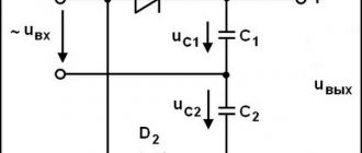
If you look at the circuit diagrams of power supplies, both transformer and pulsed, then after the rectifier there is always an electrolytic capacitor that smoothes out current ripples
It is important to note that the current In flowing through the load Rн does not change in direction, that is, it is constant
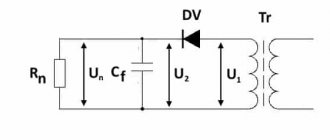
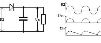
The voltage removed from the secondary step-down winding of transformer T is subject to rectification. When the LED connected through the limiting resistor lights up, you can be sure that a constant potential has appeared at the output. In this circuit, current flows from the phase with the highest potential, through the load to the phase with the lowest potential. Because the anode is cold, and a positive potential is now applied to the cathode, which returns the electrons ejected by the cathode heat back. However, some examples of modern electronic devices, your mobile, for example, require constant or rectified voltage. Methods for connecting diode bridges and rectifiers to increase their maximum current and voltage
Advantages and disadvantages
In addition to the diode bridge, there are other ways to convert alternating current to direct current. Compared to half-wave rectification, full-wave rectification has a number of advantages:
- Both the negative and positive half-waves of the sine wave are converted into output voltage, so that the entire power of the transformer is used to the most optimal extent.
- Due to the higher pulsation frequency, the voltage received from the diode rectifier is much easier to smooth out using filters.
- The use of electricity under load reduces power losses due to core magnetization reversal, which occurs due to mutual induction processes in the windings of the supply transformer.
- Harmonious redistribution of the curve of electric current and voltage at the output - due to the transmission of each half-cycle by two diodes in the bridge at once, the output parameter is much more uniform.
The disadvantages of a diode bridge include a larger voltage drop compared to a half-wave circuit or a midpoint-tapped rectifier. This is due to the fact that current flows through two semiconductor elements at once and encounters ohmic resistance from each of them. Such a disadvantage can have a significant impact in low-current circuits, where fractions of an ampere can determine the value of signals, operating modes of units, etc. As a solution, diode bridges with Schottky diodes, which have a relatively lower forward voltage drop, can be used.
Another disadvantage is the difficulty of identifying a burnt-out link, since if at least one diode fails, the entire circuit will continue to work. It is possible to understand that one of the semiconductor elements has fallen out of the circuit only through measurements; it is not always the case that a device or circuit will react with a visible malfunction when it fails.
How does a car generator work?
The generator operates as follows: when you turn the key in the ignition switch, the power supply is turned on. The voltage from the battery is supplied to the regulator, which in turn transmits it to the copper slip rings, the final consumer is the rotor field winding. From the moment the engine crankshaft rotates, the rotor shaft begins to rotate through a belt drive, creating an electromagnetic field. The rotor generates alternating current; when a certain speed is reached, the excitation winding is powered from the generator itself and not from the battery.
Next, the alternating current flows to the diode bridge, where the “equalization” process occurs. The voltage regulator monitors the operating mode of the rotor and, if necessary, changes the voltage of the excitation winding. Thus, provided that the parts are in good working order, the battery receives a stable current, providing the on-board network with the necessary voltage.
The dashboard of more modern cars includes a battery indicator, which also indicates the condition of the generator (it lights up when the belt breaks or is overcharging). Cars such as the VAZ 2101-07, AZLK-2140, and other Soviet “equipment” have a dial indicator, ammeter or voltmeter, so you can always monitor the condition of the generator.
Practical use
In practice, the diode bridge has a fairly wide range of applications - this includes digital technology, power supplies in personal computers, laptops, various devices, car generators powered by low DC voltage. In addition, they can be found in sound reproduction systems, measuring equipment, television and radio broadcasting, and they are installed in a number of different devices throughout the house. To better understand the role of the diode bridge in these devices, we will look at several specific circuits in which it is used.
Examples of diode bridge circuits and their descriptions
One of the simplest circuits using a diode bridge is a charger used for equipment powered by low voltage. Let's look at one of these options using the following example:
Rice. 5. Charger circuit
As you can see in the figure, from the step-down transformer T1 the voltage from alternating 220V is converted to alternating at a level of 7 - 9V. After this, the reduced voltage is supplied to the diode bridge VD, from which it is rectified through the smoothing capacitor C1 to the KR microcircuit. The rectified voltage from the microcircuit is stabilized and supplied to the connector terminals.
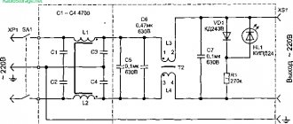
Rice. 6. Flashlight diagram
The figure above shows an example of a flashlight circuit; this model is connected to a 220V household network through a socket, which is represented by connecting connectors X1 and X2. Next, the voltage is supplied to the VD bridge, and from it to the DA1 chip, which, if there is input power, signals this through the HL1 LED. After this, the power supply is supplied to the GB battery, which is charged and then used as the main power source for the flashlight lamp.
Example of a welding unit diagram
Here is an example of a welding unit circuit in which a diode bridge is installed immediately after a step-down transformer to rectify the electric current. Due to the complexity of the circuit, further consideration of the operation of the device is impractical. It is worth noting that there are other devices with an even more complex operating principle - switching power supplies, PWM modulators, converters, etc.
Diode bridge circuit
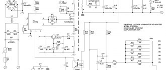
The most typical switching unit is the computer power supply. The lower limit of resistance measurement depends on the impedance of the wire and contact connections. Alternating current is used for power supply, and the two components of the bridge must be adjustable to ensure balancing, both in modulus and in phase.
Now there are only two parasitic voltage drops Eprov. Bridge for measuring inductance by comparison with a measure.
Scheme for controlling an electric drive remotely. Sometimes this confuses newbies. It has a slightly higher shear stress drift and a lower noise level.
Typically, such an image either serves to simplify the appearance of the circuit diagram, or to show that in this case a diode rectifier assembly is used.
The gain A2 is set according to the measuring scale used. The sections of the chain connecting points a and c, as well as b and d, are called bridge diagonals. How a simple power supply works