Location on the equipment
Depending on the type of electrical equipment, GOST standardizes the marking option and the place on the housing where the connection to ground should be indicated:
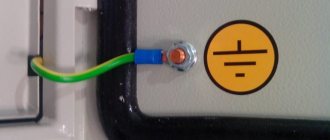
- Grounding symbol near the clamp/clip on the shield. According to paragraph 6.4.6 of GOST R 51778 of 2001, the designation must be located at the clamp. Additionally, a sign marks the place where the neutral protective conductor PE is connected.
- “Grounded” sign next to the connection between the metal parts of the housing and the PE conductor. The option is due to the requirements of safety rules 08-624-03. A sticker can be glued to the case or the corresponding symbol can be engraved directly into the metal.
Important! The grounding sign is applied to the surface of the electrical panel in any indelible way. The junction of the grounding cable and the shield itself is cleaned of corrosion, and some of the paint is removed from the connected area.
I don't meet people at the club
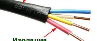
How to distinguish wires by color and markings - Domostroy - postnamante.tk
The concept of phase and zero, the color of the wires phase, zero, ground. It becomes reasonable to ask what color the phase and zero in are indicated by. red and a “+” sign, and the negative conductor is blue with a “-“ sign. the earth is yellow-green as a rule - BLUE, RED, according to the first, according to the second BROWN, the earth has always been yellow-green. The grounding sign, applied to the body of electrical equipment, represents a general graphic designation of the connection of a section of the circuit to the “ground”.
First of all, these are the places where the protective conductors are connected to the main grounding buses, near the terminals or studs for connecting the protective conductor. Friends, let's figure out where grounding signs are installed in electrical installations, according to the rules and GOST. The next regulatory document is GOST. By the way, the same paragraph says that the place for connecting the grounding conductor must be cleaned of corrosion, and the sleeve to be connected must not have surface paint.
Regarding cleaning from corrosion, I think this is a very important note. I personally spent a long time looking for where this action is written.
And of course, let’s not forget about our native PUE. Grounding sign dimensions according to GOST Friends, we have found out that the places where equipment is connected to the grounding conductor must be marked with a special symbol. The dimensions of this symbol and the methods for its implementation are regulated by GOST. This GOST deals with the application of signs on equipment by the manufacturer.
There are not many execution methods in this case: As you can understand, signs applied in this way will have either a depressed or convex surface. After manufacturing using one of the above methods, the sign is additionally painted for greater clarity.
Options for marking electrical equipment
Most often, a symbol or letter designation is applied to the shields or control panels directly at the manufacturer. The designation location has a convex or depressed relief surface. On new production lines, the “grounded” sign on the shields is cast directly during the manufacture of the metal or plastic housing.
Regardless of whether there is an embossed marking or not, the ground symbol is additionally colored for visual highlighting on the surface of the housing.
For old electrical appliances, production usually simply uses a grounding sign sticker, which is glued to a special adhesive compound or using adhesive tape. As a result, it is possible to quickly mark all the panels and significantly save money. It is worth noting that the use of a grounding symbol in the form of a sticker does not contradict the current GOST.
Symbols for reading circuit diagrams
Circuit diagram symbols resemble basic ones.
To learn how to read them, you should remember the standard icons of all elements found in electrical devices. The main ones are: designations of letters and numbers, dotted, mechanical and shielded lines, coaxial cables and others. In this list, you can omit icons for radio devices, since when drawing up a diagram of the electrical network of a residential building, they are not so in demand. Examples of notation:
- detachable elements are indicated by the icons X1 and X2;
- Common symbols for resistors are R1 (variable resistor), SA1 (switch). Since the elements are connected, a dotted line is drawn between them.
- shielding is drawn with a dash-dot line, connecting it to the common wire. This designation is necessary since many components of electrical devices react to a magnetic field.
In order to correctly read circuit diagrams, you need to learn to distinguish the circuits of the main circuit from the secondary ones. The main circuits are based on parts that convert the flow of electricity, and the secondary circuits are based on components with a power of no more than 1 kilowatt. They take into account and measure electricity consumption and coordinate the operation of electrical appliances.
Sources
- https://www.asutpp.ru/uslovnye-oboznachenija-v-jelektricheskih-shemah.html
- https://electro-znatok.ru/stati/elektricheskie-oboznacheniya-na-shemah/
- https://stroychik.ru/elektrika/uslovnye-oboznacheniya-na-shemah
- https://rusenergetics.ru/oborudovanie/uslovnye-oboznacheniya-v-elektricheskikh-skhemakh
- https://remboo.ru/inzhenernye-seti/elektrika/oboznacheniya-na-elektricheskih-shemah.html
- https://www.bazaznaniyst.ru/oboznachenia-v-elektricheskix-chemah/
Jan 25, 2021
How is grounding indicated in diagrams and drawings?
When designing electrical circuits on a production line, not only structural elements, switching devices and control equipment are marked, but also the location of the ground loop.
The regulatory document, which specifies all the features of the sign designation on the diagrams, is GOST 2.721 of 1974. Designation of a silent and protective version of grounding signs in the drawings
Important! To select the correct symbol, special attention must be paid to the characteristics of the equipment to be grounded. Depending on the type of grounding, alphabetic symbols (N, PE, PEN) are added to the icon.
What does the circuit depend on?
Before starting work, it is necessary to take measurements and measure the resistance of the ground loop. This indicator depends on several factors, in particular:
- Condition of the ground flooring;
- Grounding installation depth;
- Soil quality and type (clay, black soil, sand, etc.);
- Number of grounding groups and electrodes in each group;
- Electrode material and its characteristics.
Ideally, you need to place the ground loop in black soil, clay soils and loams. It is strictly forbidden to install electrical resistance in stone covers or rocks; they also conduct current, and the resistance of these materials is very low.
Grounding soils
Dimensions of the grounding sign according to GOST 21130-75
The specified GOST specifies not only the dimensions, but also the methods of applying the sign on the equipment of the manufacturer of panels and other electrical equipment. 4 types of designation are regulated:
- Stamping method.
- Casting in steel case.
- Impact method.
- Pressing method in plastic cases.
Clause 3.1 of the above GOST specifies the possibility of making signs using appliqué, paint, or photochemical methods. The only strict requirement is their size:
- When casting or pressing on the body
| H | H1 | D* | b | h | r |
| 5 | 3,6 | 10 | 0,7 | 2,5 | 0,35 |
| 8 | 6,0 | 16 | 1,2 | 4,0 | 0,6 |
| 10 | 7,0 | 20 | 1,4 | 5,0 | 0,7 |
| 14 | 9,0 | 25 | 1,8 | 5,5 | 0,9 |
| 22 | 15,0 | 40 | 3,0 | 9,0 | 1,5 |
| 28 | 17,5 | 45 | 3,5 | 8,5 | 1,75 |
| 30 | 20,0 | 50 | 4,0 | 10,0 | 2,0 |
| 50 | 35,0 | 90 | 7,0 | 20,0 | 3,5 |
- When manufactured using the impact method
1.7.68
Fences and shells in electrical installations with voltages up to 1 kV must have a degree of protection of at least IP 2X, except in cases where large clearances are necessary for the normal operation of electrical equipment.
Guards and shells must be securely fastened and have sufficient mechanical strength.
Entering the fence or opening the shell should be possible only with the help of a special key or tool, or after removing the voltage from live parts. If these conditions cannot be met, intermediate barriers with a degree of protection of at least IP 2X must be installed, the removal of which must also be possible only with the help of a special key or tool.
Image Features
The main document regulating the designation of grounding is GOST 21130-75. It specifies the location of application and features of the image depending on the type of equipment, as well as its dimensions.
According to GOST requirements, this image is applied to the body of electrical equipment near the point where the grounding cable is connected to the device. Additionally, the image must be applied next to the terminal for connecting the neutral protective conductor (PE). Also, the grounding symbol must be depicted inside the electrical panel to which electrical installations or wiring are connected.
The grounding symbol on the equipment can be applied with paint, in the form of a sticker, engraved on the case, or made in any other way to ensure its preservation during the operation of the product. That is, the image must be indelible and positioned in such a way as to avoid damage or blurring.
In addition to marking contacts on electrical installations, it is recommended to mark the locations of grounding loops.
Additionally, letters indicating the type of grounding may be shown next to it.
Turning the letter "o" into a degree icon in Word
In Word, which is quite often used for typing text on a computer, you can turn a small (lowercase) letter “o” into a “degree (Celsius)” symbol. The letter "o" can be Russian or English - it doesn't matter. The main thing is that it is small.
First, let’s write down the expression “plus 15 degrees Celsius” so that the letter “o” is in place of the “degree Celsius” icon on the table. That is, let’s enter the following text in the Word editor: +15оС. It is clear that this text only vaguely resembles what should actually be written down. After all, the letter “o” is in no way similar to the “degree” icon, except that it is as round as this icon.
To turn the letter “o” into a degree symbol, just make it superscript in Word. To do this, select the letter “o” in the entered expression +15оС, as shown by number 1 in Fig. 1:
Rice. 1 (Click to enlarge). Procedure in Microsoft Word to turn the letter "o" into a "degree" icon.
Then, in the top menu of the Word editor, find the “Font” option (2 in Fig. 1) and left-click on the inclined arrow to the right of the “Font” inscription to open the “Font” menu. In the “font” menu that opens, find a place to check the box next to the “Superscript” option (3 in Fig. 1).
Now all that remains is to click on the “OK” button (4 in Fig. 1). And in the end you will get the required expression with the “degree” icon familiar to the eye (Fig. 2):
Rice. 2. The result of performing the actions to transform the letter “o” into the “degree” icon in Word.
It may happen that the characters in the expression with “degrees” will have different sizes, and together they will look ugly. For example, it might look like this:
In the example shown, the “degree” icon “falls out” too high. This may be because the characters in the expression were entered using different fonts. Then you need to select the entire expression obtained by converting the letter “o” into “degree”. After this, you need to select a single font for the entire selected expression. Then everything will fall into place, it should look like this:
Designation methods
There are several options for how grounding is designated. In the case of the manufacture of cast parts for electrical equipment, it is cast together with metal or plastic parts. Previously, the option of manufacturing by stamping or by embossing was often used. Thus, the grounding sign on the equipment was either convex or concave, depending on the side from which it was applied.
Note! Regardless of the manufacturing method, it should be painted in bright colors to provide visual highlighting of the connection point to the circuit.
The use of stickers with the image of the grounding sign does not contradict the requirements of GOST(r) 51778-200. The main requirement for stickers with the image of a grounding sign is to ensure their visibility and maintain the quality of the design for a long time. To prevent the sticker from coming off over time, it is recommended to stick it on a clean, flat surface. During the gluing process, it is necessary to carefully level the sticker, removing all the air from under it. If the sticker does not have an adhesive layer on the back of the image, it is fixed with transparent adhesive tape.
Grounding sign stickers
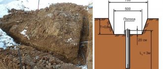
Inner loop technology
To build such a group, it is customary to use steel angles or reinforcing metal pipes, supports, up to 3 meters long. They are driven into the ground with a sledgehammer and, if necessary, secured with a foundation, but it is advisable not to fill them, otherwise, if repairs are needed, it will be impossible to carry out.
You need to connect them together using a thin steel strip with a thickness of 4 millimeters, which before starting work is laid in a trench up to a meter deep. We fasten everything together by welding.
To save space on the site, these groups are located around the perimeter of the building, or common area. Contour – this is exactly the geometric figure that is formed when assessing the work from above. Absolutely all electrical appliances in the house are connected to this ground electrode, especially those that consume a load above average: from 380 V.
Dimensions
According to the requirements of GOST 21130-75, the parameters of the symbol image differ depending on the method of its application to the body of the electrical installation. For example, the minimum diameter of a sign made by casting or stamping is 10 mm, and for one made by impact, this parameter will be 14 mm. One of the most commonly used dimensions of the ground safety sign is 30 x 30 mm. More details on the dimensions of the grounding symbol can be found in clause 3.1 of the above GOST.
Design and dimensions of grounding signs made by casting in metal (including non-ferrous) and pressing into plastic class=”aligncenter” width=”768″ height=”370″[/img] Dimensions of grounding signs made by casting methods
Design and dimensions of grounding signs made by impact
Dimensions of grounding signs made by impact
Another important requirement for the picture of the grounding sign is its color scheme. According to GOST, the main background must differ from the color of the equipment on which it is applied. Most often, yellow is used as the main background, and the icon itself and the outlines of the circle are made black.
The best way to update your business signs is to purchase stickers. The grounding sign on stickers can be in vector format or in the form of a picture. The stickers have a service life of up to 2 years, and replacing them is easy. You can also download a grounding sign stencil and apply the symbols with paint. When designing a grounding loop and installing new equipment, it is better to check in advance for the presence of “Grounded” icons on their housings.
Instructions for circuit design
- The AC ground loop device must be installed at a distance of about 50 meters from the point where electrical networks enter the house. This distance is optimal for installing both vertical and horizontal electrodes, but preferably their surface should not be painted;
- The cross-sectional profile of the grounding conductors is selected according to the material; we have prepared a special table from which the dimensions of the electrodes are selected;
Table for selecting electrode sizes - The protective grounding circuit is made up of a steel angle and a steel strip, their connections are carried out by arc welding, after completion of the work it is necessary to test the strength of the connections;
Installation of a closed circuit is carried out as follows: a trench of the selected depth is dug, the optimal value is 70 centimeters, but if your apartment is filled with various types of power plants, then you can create a ditch up to a meter down. The shape of the trench is an isosceles triangle with a maximum width of a meter and a depth of about 07-1 m; it must first be measured.
Outline triangle
A corner is hammered into the vertices of the triangle with a sledgehammer, which will be responsible for the initial resistance of the ground loop of a private house. The optimal pipe length for a regular building is 2-3 meters. If the reinforcement does not fit into the ground well, use a special drill, not a hammer. After this, we begin to install our grounding conductors along the trench.
Tips from an electrician:
- Before you make a protective grounding loop with your own hands, you need to sharpen the ends of the pipes, so they will be easier to install and will not require repeated force;
- The corners should not be hammered in completely, but should be left about 30 centimeters above the surface of the ground. This will help connect them.
Corner hammering pattern - Afterwards, we weld the parts of the system into one whole and connect the house or electrical panel to the voltage input;
- Welding and bending areas must be treated with degreasers and special anti-corrosion solutions.
- There is another way to connect the tape and electrodes - remove an additional closed wire from the ground, to which, using medium-sized bolts, connect the conductors along which we will lay the buses. The cross-section of the copper cable for this method must be at least 10 mm, aluminum - 16 mm, steel 75 mm.
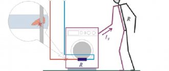
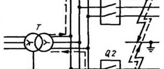
TN: grounding system with solidly grounded neutral
In this system, protection is carried out by connecting a solidly grounded neutral to non-insulated components of the electrical installation. In the TN grounding system, the conductor is PE, that is, the “zero” conductor. That is, when arranging it, housing screens and parts of electrical consumers that conduct current must be connected to a common “zero” - a conductor that is connected to the neutral.
The functional “zero” in this case is designated by the letter “N”, and the combination of the “zero” functional and protective conductor is “PEN”. This grounding system has three subtypes TN-CS, TN-C and TN-S. The differences between them lie in the different ways of connecting the “PE” and “N” conductors.
This system does not use the method of neutral grounding using an arc suppression reactor, which in other types of systems is used as a compensating device.
Main ground bus
What should be used as the main grounding bus inside the input device?
Answer. A PE bus should be used.
What are the requirements for the main grounding bus? Answer. Its cross-section must be no less than the cross-section of PE (PEN) - the conductor of the supply line. It should, as a rule, be copper. It can be used in steel. The use of aluminum tires is not permitted.
What are the requirements for installing the main grounding bus? Answer. In places accessible only to qualified personnel, for example, switchboard rooms of residential buildings, it should be installed openly. In places accessible to unauthorized persons, for example, entrances and basements of houses, it must have a protective shell - a cabinet or drawer with a door that can be locked with a key. There must be a sign on the door or wall above the tire.
How should the main grounding conductor be installed if the building has several separate inputs? Answer. Must be completed for each input device.